1926 Atwater Kent Model 30


This is a 6-tube battery-powered set made by Atwater Kent Radio of Philadelphia, PA. Shown with the radio is a Model L loudspeaker. This arrangement is the classic antique radio seen in many old movies and photographs.


The radio is housed in a narrow wooden box (the Model 30 box is slightly wider that the Model 20 box). The radio is a Tuned Radio Frequency (TRF) radio using a grid leak detector. Tuning of the 2 RF stages and the detector stage is accomplished using a single knob on the front. The knob dial is calibrated from 0 to 100.

The knob cluster on the far right contains 2 rheostats and the On/Off switch. The rheostat on the left controls the filament current to the 3 RF amplifier tubes. The rheostat on the right controls the filament current to the detector tube. The two audio tubes have a fixed resistor in series with the filaments. You adjust these rheostats to obtain the desired volume and clearest undistorted sound. The On/Off switch is pulled out to turn the radio on and pushed in to turn it off. Basicly, the switch disconnects ground from the filaments.

When received, the radio had several problems that could be fixed with some effort. The radio had the following problems:
- the pulleys on the 3 variable condensor shafts were cracked; one was broken in half
- one copper band used as a belt was broken; the other was missing
- the secondary of the 1st audio transformer was open
- the grid resistor in the 2nd RF stage was open
- the grid leak resistor was open

However, all of the tubes turned out to be good!

Below is a picture of the 3 pulleys that were bad. They are shown in the order attached to the shafts of the three tuning condensors. Also shown is one of the copper bands that wraps around the pulleys and one of the brass pins that is pressed into the pulleys.


The pulley in the center is broken in half and is the drive pulley for the other two. The dial is also attached to the same shaft to which this pulley is attached. Two copper bands wrap around the center pulley and one of the other two pulleys. Only one band was present when I received the radio. Brass pins (one can be seen in the picture) are mounted in each pulley (2 pins are mounted in the center pulley). The cooper bands have holes that fit over the pins to ensure no slippage.

To repair the tuning drive system, I purchased 4 pulleys (1.75 inch diameter) made of Delrin. I drilled and tapped a 4-40 hole in each and installed a set screw to fasten them to the condensor shafts. I drilled two 0.040 diameter holes in each pulley drive surface. I then mounted the pulleys on the condensor shafts (2 pulleys were mounted to the center condensor shaft) and used magnet wire for the copper bands. The picture below shows the new tuning mechanism. The mechanism works well with no slippage.


The radio chassis has a layout similar to the Atwater Kent Model 20 and the Atwater Kent Model 42 I have. Below is a picture of the rear of the radio chassis removed from the case.


Below is a picture of the top of the chassis. Five of the tubes are balloon-type 01A tubes. The detector tube (4th tube from left) is a 200A type tube.


Below is a picture of the bottom of the chassis. On the left, you can see the green, red, and blue wires from the replacement interstage transformer I installed inside the original cylindrical can enclosure.


To repair the defective transformer I had to melt the tar out of the cylindrical can enclosure. It is the transformer in the large can that had the open secondary winding. I removed the can from the chassis, mounted the can on two wood blocks, placed it on an aluminum pie pan right-side up, and placed it in an oven. I set the oven for 275 deg F. and after 1.5 hours, most of the tar ran out of the can into the pie pan, and I pulled the defective transformer out of the can with pliers.

Below is a picture of the transformer in the oven. You can see a blob of tar emerging from the bottom of the can. The transformer is also beginning to slip out of the can.


Below is a picture of the transformer I pulled out of the can.


I received a manual with the Atwater Kent Model 20 that I purchased earlier. The manual is quite interesting. It contains information on how to install antennas, how to connect the batteries, and how to operate the Atwater Kent Model 30, 32, 35, and 20 Compact radios. It also discusses how to use a higher power audio tube for the second audio amplifier - essentially is requires a higher plate voltage (135V) and a "C" battery. Below is a picture of the front of the instruction book. The inside title page shows a sketch of the Atwater Kent factory. A picture of it also is shown below. It apparently was a very large factory.


The book also showed several pictures of installations of the Atwater Kent radios. Below are two such pictures from the book showing the Model 30 and the Model L horn loudspeaker.


Below is a page from the book showing the location of the tubes and controls for the Model 30. This picture shows the earlier model of the Model 30. I have the later model as evidenced by the fact that the coils in mine are a smaller diameter that the ones in the picture. The coils in mine are similar to the Atwater Kent Model 42 that I have.

Here is a page from the book showing the dial settings (in wavelengths) for the Model 30.

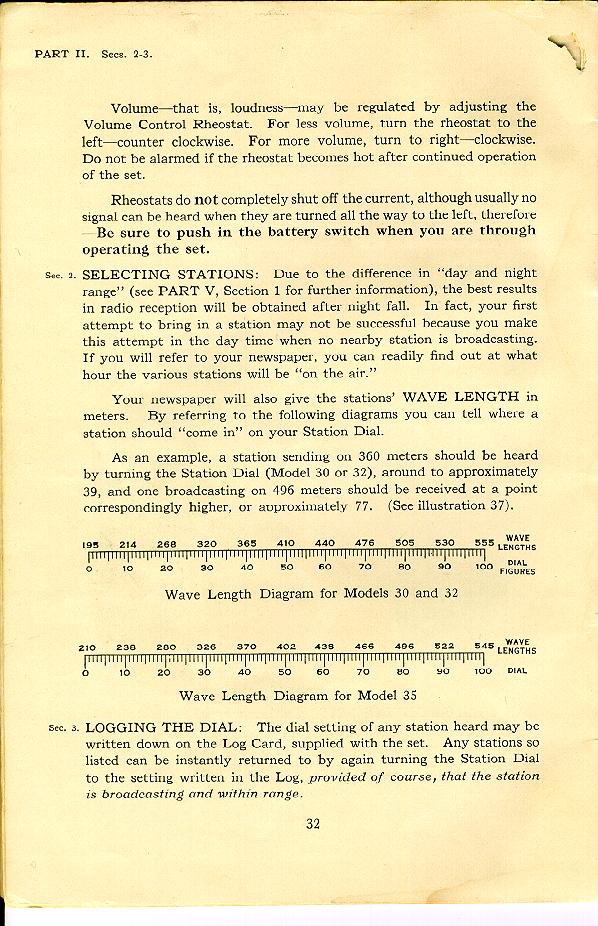
Finally, here is a page from the book that shows how to hook up the cable to the batteries. Note that 4 batteries providing 5 voltages are required to operate this radio.
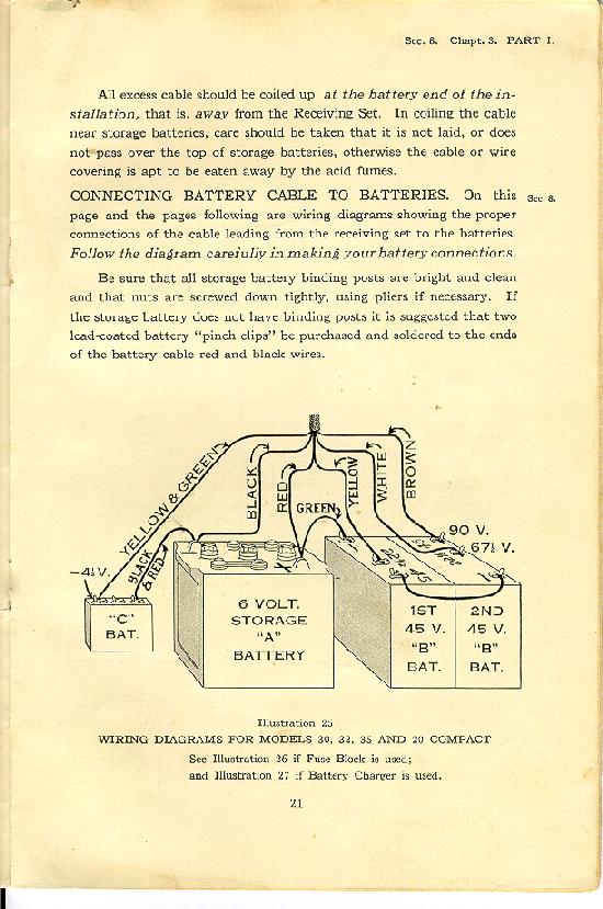

Tube Compliment

Ballast
Rectifier
RF
Osc
Osc/Mix
IF
Det
1st Audio
Audio Output
Tuning Eye
Rider's Manual Page #
N/A
N/A
3 x 201A
N/A
N/A
N/A
200A
201A
201A
N/A
1-4


Inside the radio I found a tag that apparently was originally attached to the power cable. One side of the tag identified the required battery voltages and indicated which wire by color in the cable to connect to the batteries. The other side of the tag contains text describing the connections if a power tube is used for the audio output. A picture of both sides of the tag is shown below. Note the date on the tag is 1926.


The colors of the wires had faded over time. Only the black and the green with yellow tracer wires were recognizable. So I had to run a continuity check to ensure I had the correct wire identification.

The radio works well now using a power supply I built. A picture of the power supply I built to power the 5-Volt filament tube battery sets is shown below.


With a long wire antenna, I can recieve WSM in Nashville (100 miles north) quite well.


Below is a picture of the radio with the top open.


Below is picture of the model number tag on the inside of the lid. Note the sticker below the tag. It must refer to the store that sold the radio.


Below is a picture of the warranty tag located on the bottom of the radio. Note the date is October 1926.


Home