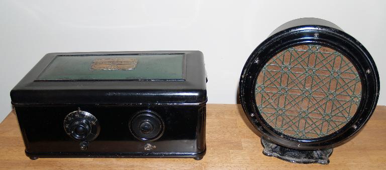
This radio is similar to the Atwater Kent Model 42 that I have. The major difference is that the Model 46 has a push-pull audio output stage using two #71A triode tubes. This arrangement gives greater output power. The Model 42 uses a model F2 speaker, shown in the picture above. The speaker is an electrodynamic speaker where the B+ voltage is run thought the field coil. The speaker shown above did not come with the radio. I acquired the speaker later. Fortunately, the 4-prong speaker plug completete with an attached 4-conductor cable came with the radio. I substituted a 1.7k-ohm 5W resistor for the field coil to use the radio with a permanent magnet speaker to test the radio and get it working.
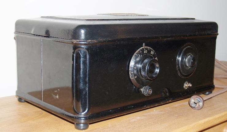
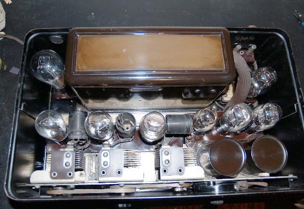
When recieved, the radio was quite dirty as shown in the picture below. In addition, the dial knob was broken into about 8 pieces when I received the radio.
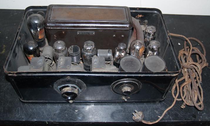
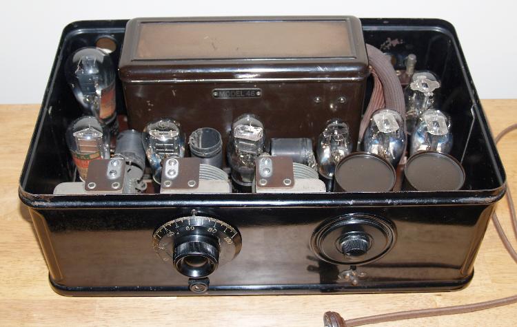
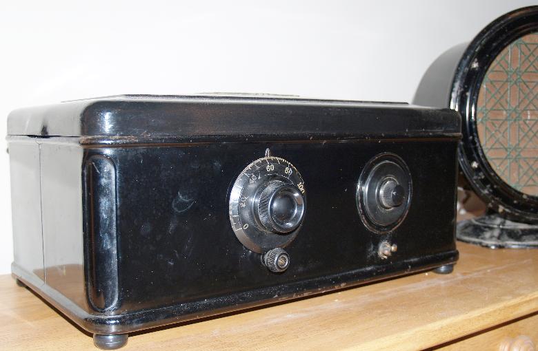
The radio cleaned up nicely as shown in the first picture. Below is a picture of the radio after I cleaned it using spapy water and then waxing it with a car cleaner and wax. The inside cleaned up nicely and has no rust. The paper strip on the botton between the electronics and the power supply that lists the tubes is still there and readable. Note that three of the tubes are of the older "globe or balloon" style glass envelope. The #80 dual rectifier tube shown on the top left of the chassis is a globe style tube.
There were three tubes that were bad when I received the radio; one #26 and one #71A had open filaments and one #26 had a good filament but it had very low gain. I checked out all of the other components in the radio and power supply and found no other defective components. The power supply capacitors were good and even both audio transformers were good! (Typically one of them is bad) I did replace the cathode resistor on the detector as someone previously had replaced it and left the replancement hanging loose. I also replaced the power cord as it was frayed in several places, but I saved the original plug and attached it to the new power cord. Also, the original grid leak resistor had been replaced with a "doggy-bone" resistor that is still good.
After cleaning up the radio and replacing the bad tubes and the one capacitor, I brought the radio up slowly with a variac. The radio played well, picking up many stations. I used plastic epoxy to glue back together the pieces of the broken dial. I attached 4 rubber feet to the bottom of the case.
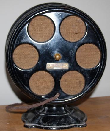
Later I acquired the Model F2 speaker shown in the first picture. It was also quite dirty and I cleaned it up with soapy water and car cleaner/wax. The speaker has may places where the original paint has disappeared. The speaker has the same color scheme as the radio as the speaker grill is green to match the lid of the radio.
The 4-conductor line cord attached to the speaker is good and contained the 4-prong plug. The resistance of the field coil measured to be 2.45k ohms, which is significantly higher that the specified 1.7k ohms. The voice coil resistance measured to be almost zero ohms. The speaker works, but the sound is distorted and somewhat "tinny". It appears that either the paper cone is too stiff or something is preventing complete movement of the speaker.
I took the speaker apart, to see if something was restricting the movement of the cone. Although the speaker was dusty inside, I could not see anything else wrong. Below is a picture of the inside of the speaker.
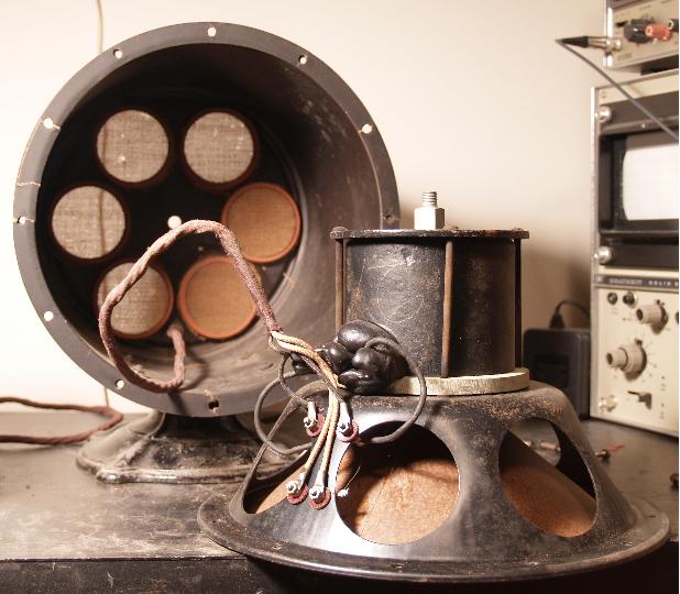
The speaker is held inside the enclosure with the bolt seen on the top end of the enclosed coil assembly. There are 4 terminals on the side of the speaker where the cable attaches. Tar is used for a strain relief for the two wires connected to the field coil. Below is a picture of the rear of the speaker.
3-17 |