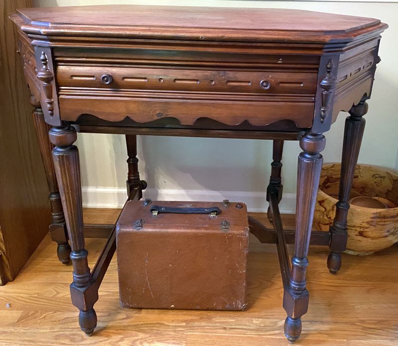
Below is a picture of the table with the front panel closed.
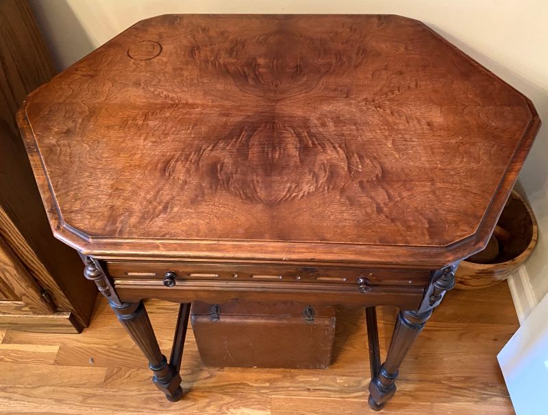
Below is a picture of the table top. The top has an unusual wood grain pattern repeated at the front and rear. There is a water ring at the left rear.
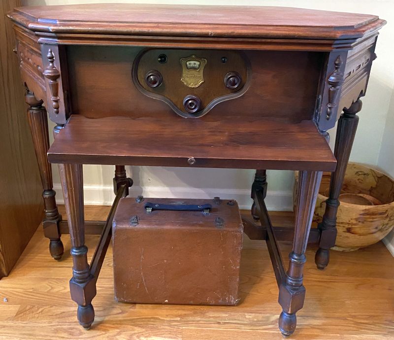
The table top lifts up to provide access to the radio. The table with the top lifted up and latched into place is shown below.
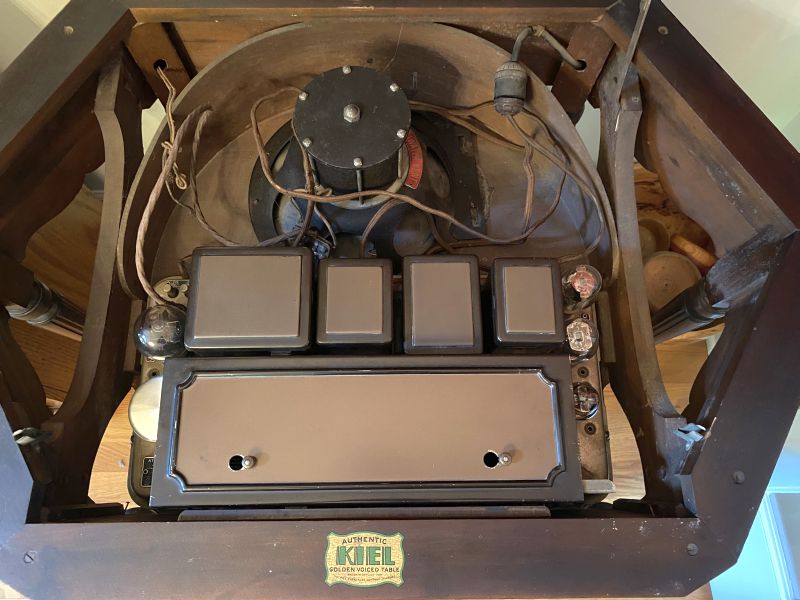
The radio and speaker are not secured to the table - they just sit freely in position. Power is brought into the radio through the rear table leg on the right hand side in the picture. In the picture, you can see the radio plugged into a socket attached to the wires that go through the table leg. Antenna and ground are brought to the radio through the other rear leg on the left in the picture.
Note in the picture that the table is referred to as an "Authentic Kiel Golden Voiced Table." This can been seen on a decal attached on a table member in front of the radio.The table was in reasonably good shape and I used Howards Feed-N-Wax to make it look a lot better.
The table did not have the radio when I received it. Over time, I acquired the radio and speaker separately.
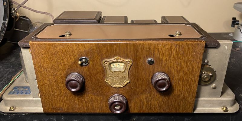
Below is a picture of the front of the radio chassis.
Below is a picture of the top of the radio chassis.
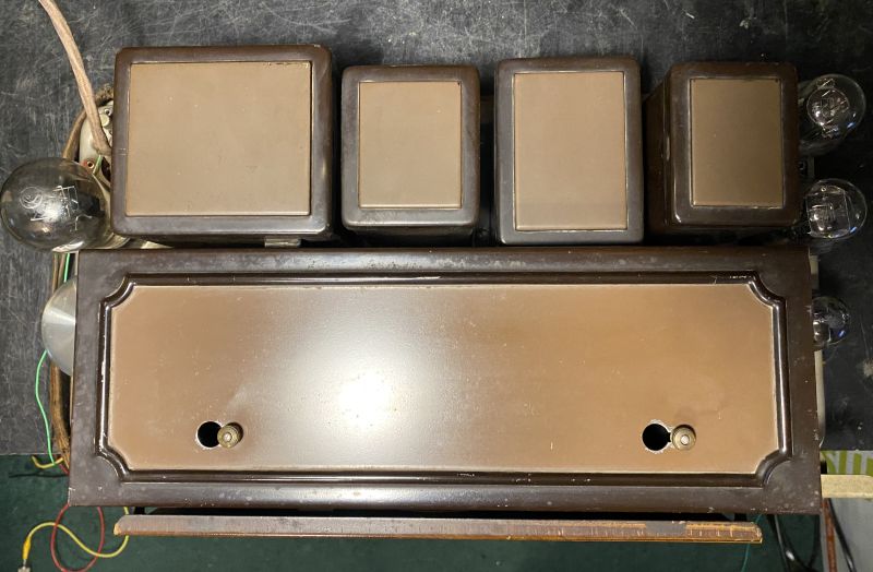
This radio has seven vacuum tubes with a push-pull audio output stage using two #245 triode tubes. This arrangement gives greater output power. In the picture above, the #280 rectifier is the vaccum tube seen on the left-hand side, the two #245 vacuum tubes are the two seen on the uppper right-hand side. The vacuum tube below the two #245s is a #227 that is the first audio frequency amplifier.
The four rectangular boxes at the top of the picture are the power transformer, filter choke assembly containing two chokes, a filter condenser (capacitor) assembly containing several capacitors, and the audio frequency transformer assembly containing two transformers. The cover at the bottom of the picture is over the radio frequency (RF) section. A picture of the RF section with the cover removed is shown below.
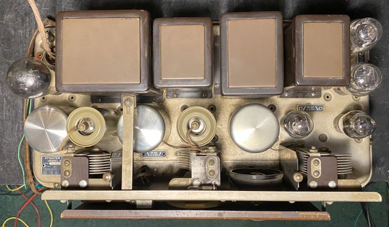
The vacuum tube on the lower right-hand side is another #227 that functions as a grid leak detector. The two vacuum tubes in cylindrical shields with grid caps are #224 RF amplifiers.
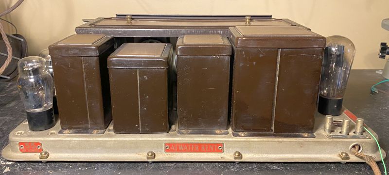
Below is a picture of the rear of the radio chassis.
Below are pictures of the bottom of the radio chassis with and without the bottom cover in place.
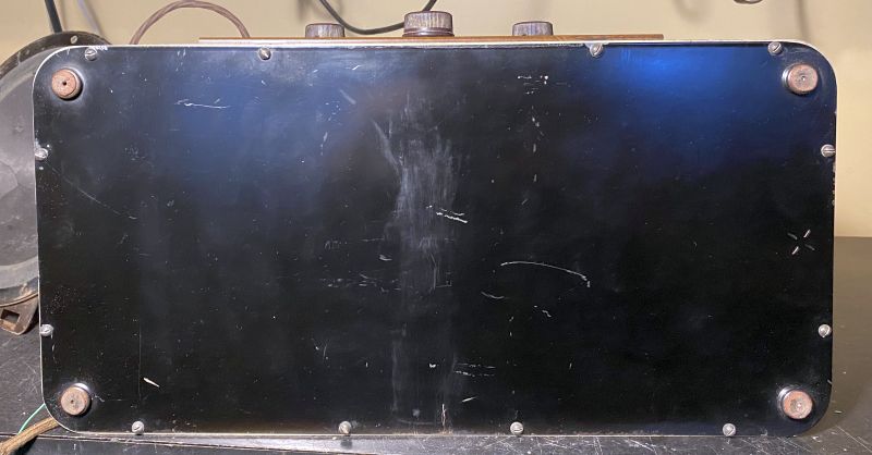
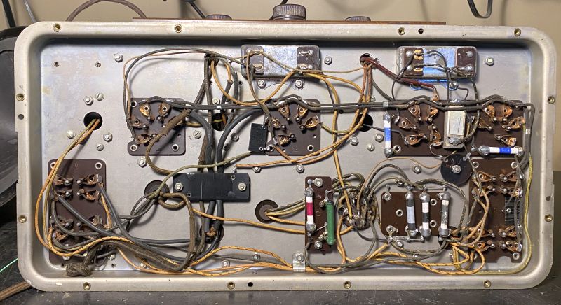
As evident from the last picture, nothing has been done to restore the radio.
However, the tuning knob (the center knob) did slip on occasion and not turn the dial. I removed the front cover to investigate. The radio with the knobs and front cover removed is shown below.
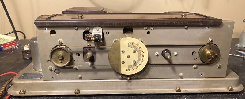
It turns out someone previously did attempt to address this problem by wrapping adhesive tape around the tuning shaft. The original rubber grommet had disentigrated. I also wrapped tape around the shaft and the problem is repaired. As can be seen in the picture, the dial has no back light to indicate the radio is on or to facilitate seeing the dial in a dimly lit room. The dial is translucent, though.
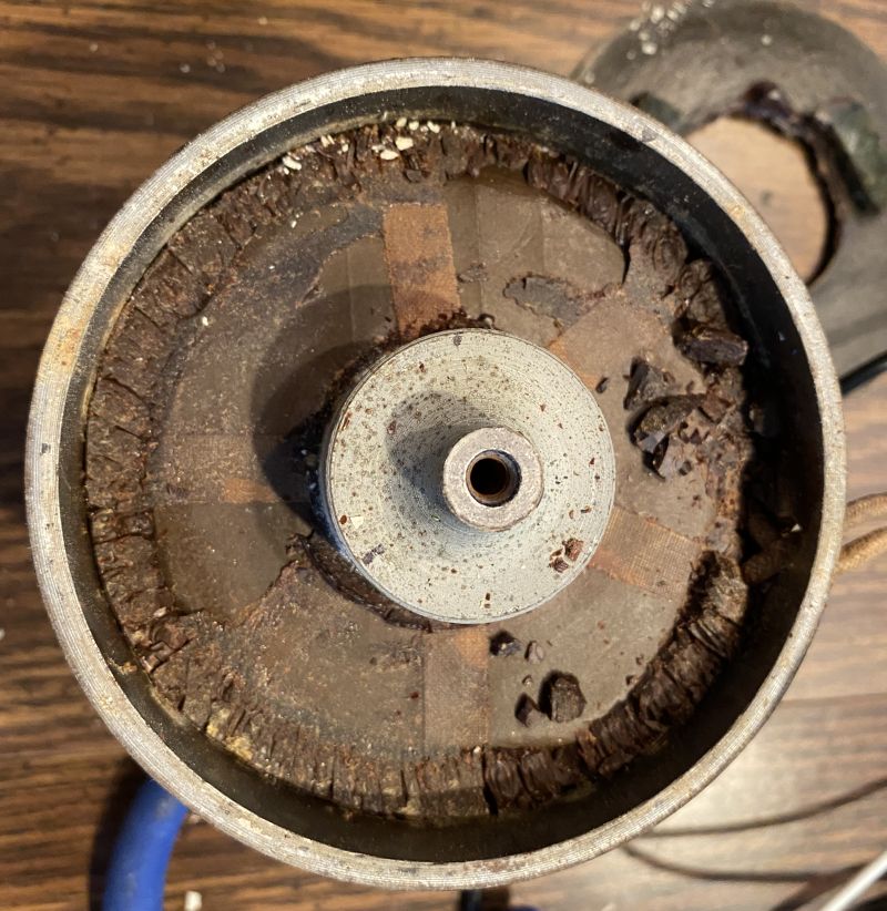
The radio uses a model F4 speaker shown the the first picture above. The speaker is an electrodynamic speaker where the B+ voltage return from ground is run though the field coil. The speaker shown above did not come with the radio. I acquired the speaker later. Below is a picture of the speaker when I received it.
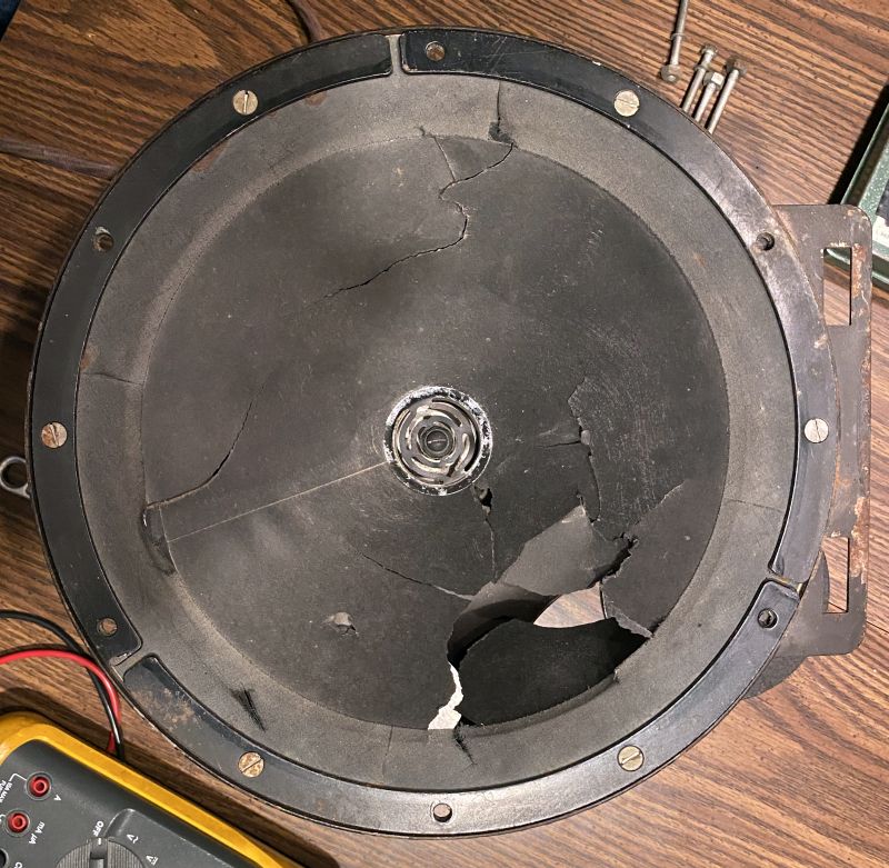
Note that the speaker has numerous rips and tears in its cone. However, the field coil and voice coil were good except the resistance of the field coil measured higher than the stated resistance of 1.1k ohm. As such, I decided to take the speaker apart to investigate. Below are pictues of the field coil removed from the speaker.
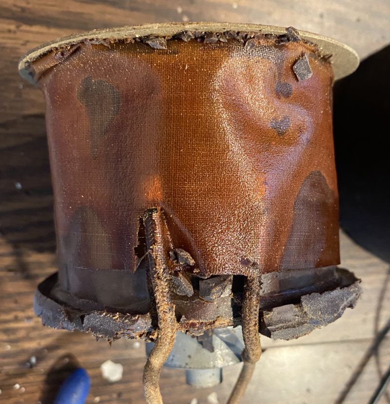
I could find nothing wong with the field coil and after reassembly and test, the reistance measured 1k ohm.
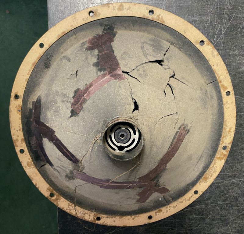
While having the speaker disassembled, I repaired the speaker cone. The cone is easily removed from the speaker frame and field coil. It is held in place with numerous screws. I repaired the rips and tears using thin black tissue paper dipped in a mixture of white glue and water. A picture of the speaker with my repair in progress is shown below.
I reassembled the speaker and connected the speaker to the radio. I measured resistiance to ground on the B+ Voltage lines to confirm there were no short circuits. Seeing no short circuits, I very slowly brought power up using a variable transformer while monitoring the B+ Voltage. The voltage came up and was stable indicating the power supply filter capacitors were good and holding up under voltage. I injected an audio tone into the audio stage and heard audio from the speaker. I then injected amplitude-moduated RF into the antenna terminals and hear sound from the speaker. Then I connected the radio to an antenna and heard WSM from Nashville, TN with plenty of volume. WSM is received at about 670 (red numbers) on the dial. Thus, the radio works without me having to repair anything or replace any tubes!