To properly test and operate my antique battery radios, I designed and built a multi-voltage power supply. Most of the old battery radios require several defferent voltages that were originally supplied by using several batteries, some of which had taps for more than one voltage. The filament supply was typically a large single battery, and was referred to as the "A" Battery. It was faily physically large as it had to supply significant current for the filaments.
Other batteries supplied the higher voltages for the plates of the tubes and was referred to as the "B" Battery. Different stages of the radio required different voltages with the audio output stage having the highest "B" voltage. These higher voltages were typically multiples of 22V, so one could string together several 22-V batteries in series to obtain the required voltages. These batteries did not have to supply the large amount of current as the "A" Battery had to so those batteries could be physically smaller than the "A" Battery.
The final required voltage was referred to as the "C" Battery. The "C" battery typically supplied a negative bias to the audio output tube and did not have to provide a large amount of current. Not all battery radios required this battery.
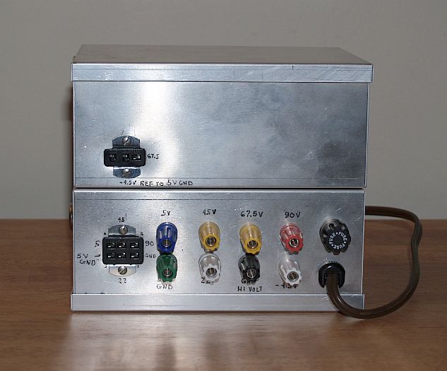
I built my power supply to supply all of the typical "A", "B", and "C" voltages up to a maximum of 90V. Some radios used 135V for their audio output tube, but I fould I did not require this voltage often and have used 90V instead. My power supply provides 22V, 45V, 67.5V, and 90V for the "B" voltages. The "A" Voltage is 5V. The "C" voltage is -4.5V relative to the 5V supply.
In the picuture above, all the voltages are available on color-coded bannana jacks and on recessed terminals of Cinch-Jones sockets. I used the bananna jacks for quick tests and for powering my Atwater Kent box radios. On other battery radios, I attached a Cinch-Jones plug to the radios so I can quickly plug the radio into the power supply and use the radio. Using the Cinch-Jones plugs also helps prevent inadvertent wrong connections to the power supply.
Below is a pictue of the front of the power supply showing the on/off power switch.
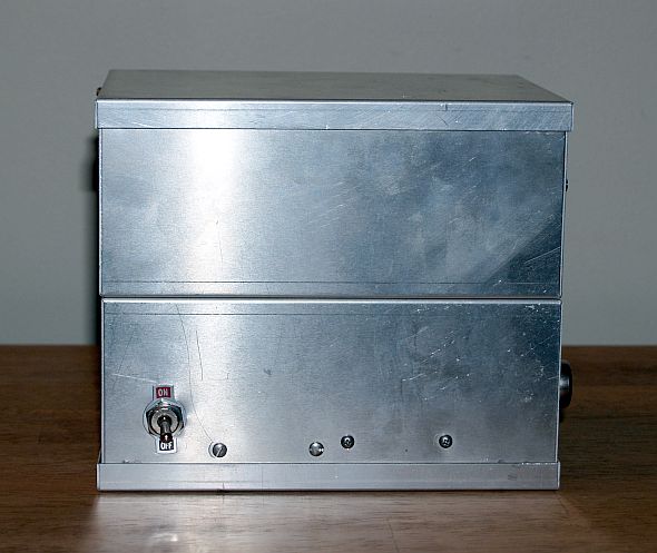
I can turn the power supply (and radio) on and off with this switch, but for initial testing and also to reduce the on-surge of current to the filament, I typically bring the power supply up slowly with my variable transformer (Variac).
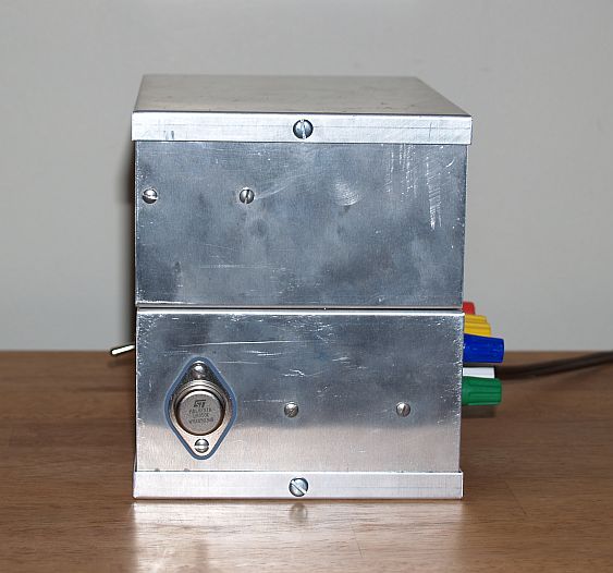
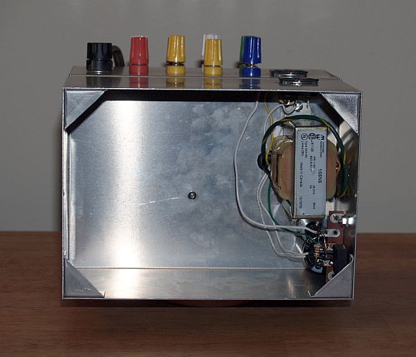
The picture below shows one side of the power supply and the voltage regular that supplies the filament current.
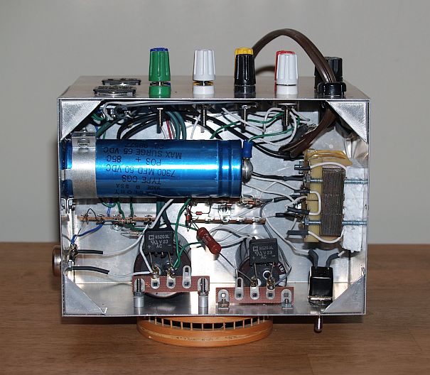
The picture below shows the inside of the top of the power supply.
The picture below shows the inside of the bottom of the power supply.