
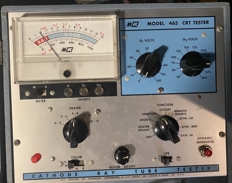
The picture above is of a B&K Model 465 Cathode Ray Tube (CRT) Tester. This instrument will test a cathode ray tube for all of the important factors that deermine the quality of the tube.
The instrument will check for shorts or leakage between elements in the tube up to several megohms. It will also indicate between which elements the fault exists.
The instrument will check for the amount of emission from the cathode of a tube.
The instrument will check the cutoff characteristics of a tube. Cutoff voltage indicates the amount of picture contrast the tube can produce.
The instrument will repair most of the common faults in cathode ray tubes, such as shorts between elements, open connections to elements, and inter-element leakage.
The instrument will rejuvenate picture tubes that have low emission.
The instrument will perform all of the above tests and repairs on most tubes, including the "low G2" tubes that require 50 V or less of G2 potential and tubes operating with low emission currents.
Below is a picture of the inside of the tester chassis. I removed the chassis from its case to adjust the calibration potentiometer becasue the heater voltage reading on the meter read lower than the actual voltage. A little adjustment of the potentiometer fixed that problem. The production date stamped on the meter (viewable in the picture below) indicates this instrument was manufactured in 1968.

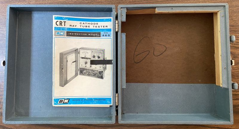
Below is a picture of the inside of the meter case.
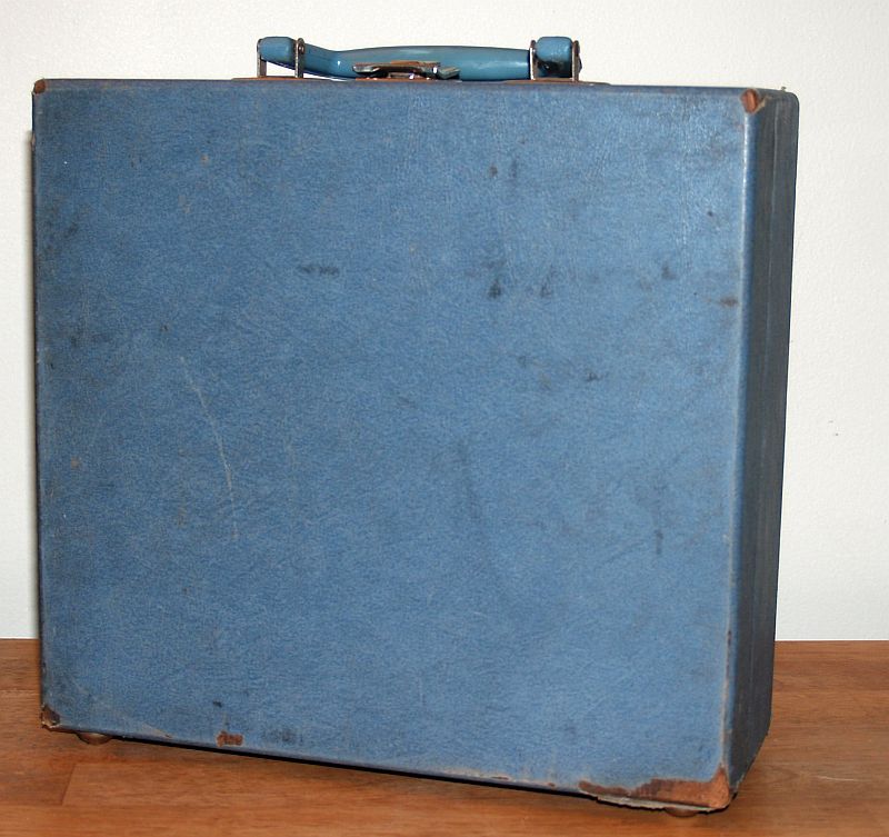
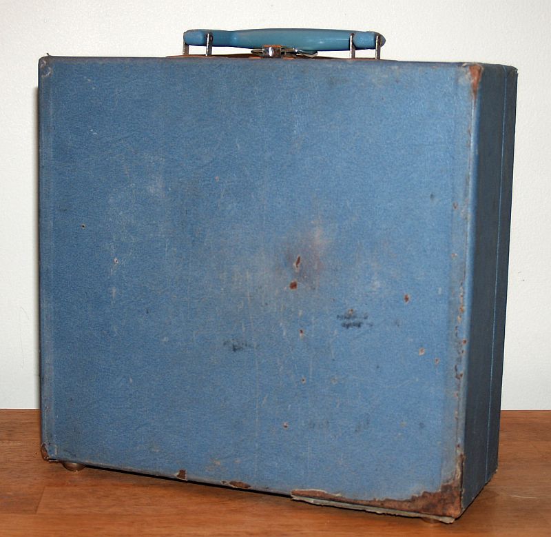
The meter is housed in a wooden case that has a blue vinyl covering that cleaned up reasonably well. Only a little of the vinyl is missing as can be seen below.

I checked out the heater voltage and the G1 and G2 voltages before using the meter to actually test a CRT. The G2 knob was loose and I repositoned and tightned it to align the pointer with the numbers that indicate grid voltage while measuring the actual grid voltage on the appropriate "regular" socket pins. The G1 knob required no realignment.
Below is a picture of the tester showing 6.3 V heater voltage.

Below is a picture of a CRT heater being powered by the tester.The CRT is in the Admiral Model 20X122 TV I am restoring.
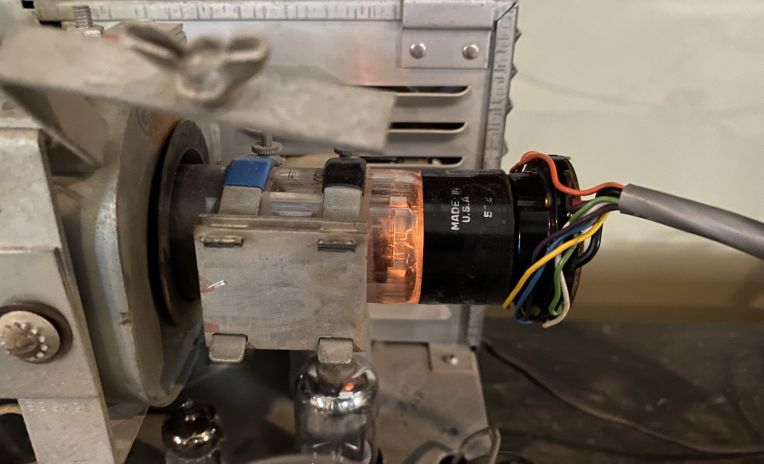
There were no shorts indicated on the picture tube being tested above. However when the knob was positioned to the "Emission" position, the meter read zero, indicating a bad picture tube. But after waiting several minutes, the meter began to rise as shown below.
After waiting longer, the emissions read into the "Good" region as shown below.

This is the first time this tube has been "turned on" in over 60 years. As such, it is not surprising to observe this slow start. I decided not to try to rejuvenate the tube to improve emissions at this time. I will finish the televison restoration and see what the picture actually looks like and then decide. My expectitation is that the emission may improve with a little use after the television is operational.
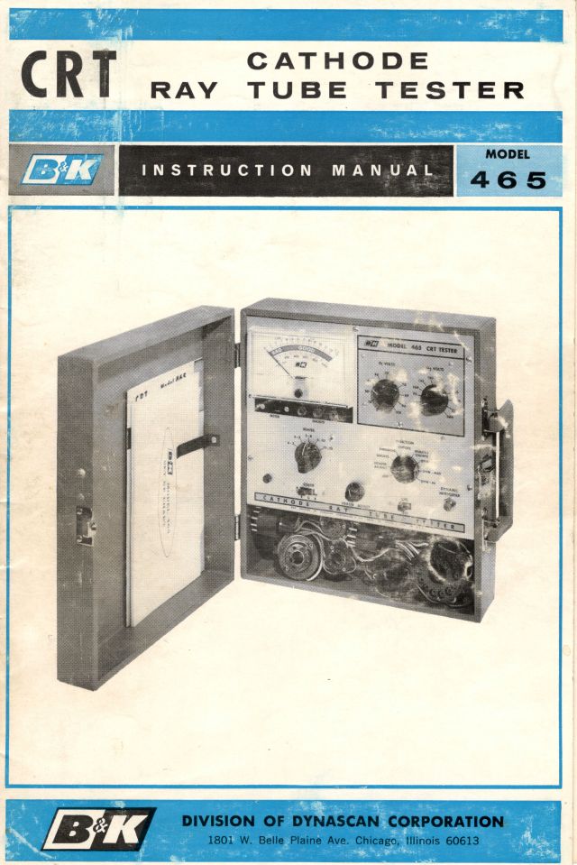
In the first picture, it can be seen that 4 adapters are included with the tester to accommodate various CRT socket pins. I also have the manual for the tester.The cover of the manual and the electrical schematic of the tester included in the manual are shown below.

The intrument also had two setup charts included with it. The covers of the charts are shown below.
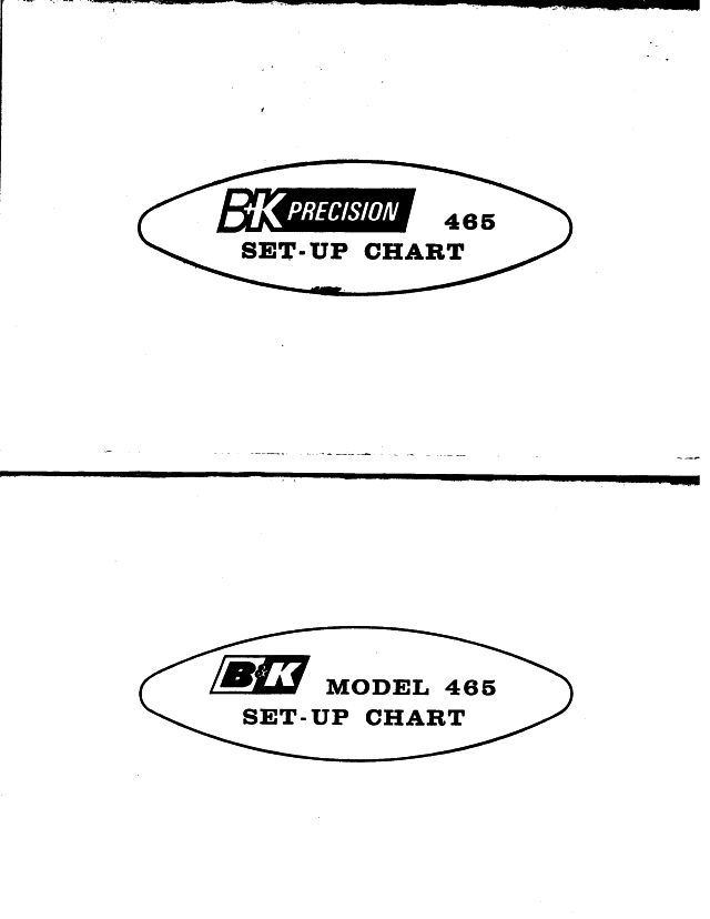
Note that the B&K logos are different for the two setup charts. The setup chart with "Precison" added is apparently a newer (and thicker)chart that refers to a new adapter/converter to extend the useful life of the instrument. The first pages of that setup chart are shown below.
