The radio has 3 tuned RF stages. The detector stage is also tuned making a total of 4 tuned stages. All stages are tuned simultaneously. There is a fine tuning control that tunes the first stage. It might be considered an antenna trimmer. The primary windings of the RF transformers coupling each stage is center tapped to which the B+ is applied. One end of the winding is connected to the plate of the tubes; the other end is connected to a capacitor that feeds back some of the output to the grids of the associated RF tube - hence the name "counterphase." The radio uses a grid leak detector and a push-pull audio output.
All of the tubes that came with this radio were good. However, one half of the secondary winding of the first audio transformer was open. I installed a new transformer under the chassis and bypassed the original transformer that is installed in the metal enclosure at the rear of the radio. Also, one of the wires connected to the power converter had broken off its terminal in the power converter. I resoldered it and the radio works well now. The radio is very sensitive receiving WSM in Nashville, WBBM in Chicago, and many others.
The only complaint I have is that the dial is not accurately calibrated. WSM at 650 kHz is received at about 580 on the dial. I cannot see any way to align the radio. I can add capacitance in parallel with each tuning capacitor and bring the lower end within calibration, but the high end will be significantly off. I decided to leave the radio as is because it works well otherwise.
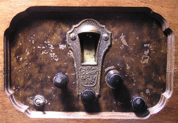
Below is a closeup of the control panel of the radio. The paint on the metal recessed panel is gone in several places. The knob to the lower left of dial window is the volume. The knob to the lower right of the dial window is tuning. The knob directly below the dial window is the antenna trimmer. The on/off switch is left and below the volume control. The knob below and right of the tuning knob is the 2-position tone control.
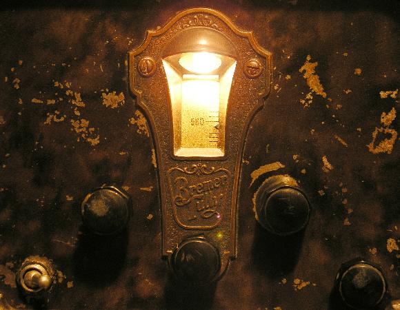
Below is a picture of the control panel with the radio on and operating.
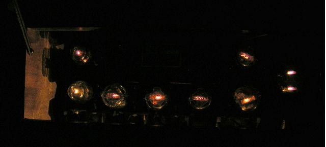
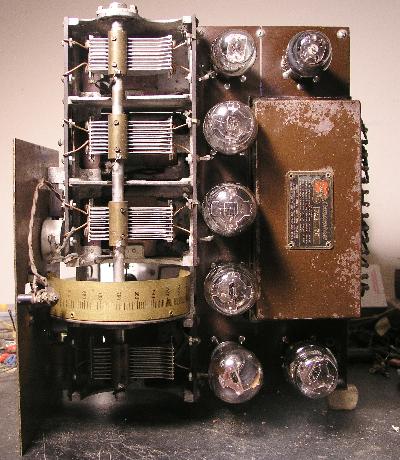
Below is picture of the top of the chassis removed from the cabinet. Note the tube at the bottom of the vertical line of tubes with the globe glass envelope. It is the first RF amplifier and is a Philco #26 tube.
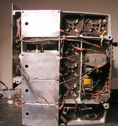
Below is a picture of bottom of the chassis. You can see the transformer I added.
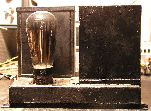
Below is a picture of the power converter. Notice the #80 rectifier tube with the globe glass envelope. It is a Cunningham tube.
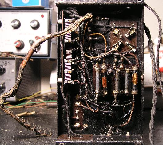
Below is a picture of the bottom of the power converter.
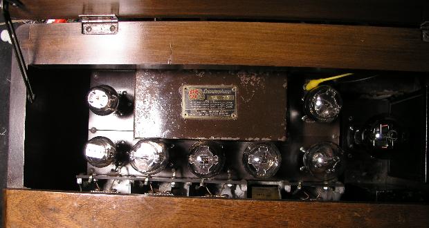
The picture below shows the chassis top as seen through the hinged cover of the cabinet. The yellow clip lead on the right is one of the connections I made to an external speaker.
Below is the same view with the room lights off and you can see all the tubes illuminated.