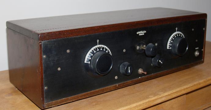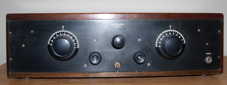
It is battery powered and has 3 tubes and is a regenerative receiver. The first tube is an RF amplifier - audio amplifier combination. The second tube is a regenerative detector. The third tube is the second audio amplifier that drives an external speaker. If using headphones, the third tube is not used. Tuning is accomplished by selecting one of 4 taps on the internal antenna loading coil and then turning the 2 large dials until the desired station is heard. Feedback for regeneration is accomplished by pulling the knob located in the top center of the front panel in and out. Pulling it out increases the coupling and therefore the feedback. Optimum operating point for regeneration is just at the point of oscillation. Below the feedback knob is a brass post that is pulled out/pushed in for the on/off switch for the tube filaments. The two knobs with the arrows control the voltage to the filaments for the tubes. The arrow knob on the left controls the filament voltage for the first RF amplifier - audio amplifier tube and the second audio amplifier tube. The arrow knob on the right controls the filament voltage for the detector tube.
This is a large radio measuring 21 1/4 inches long, 7 inches high, and 7 3/4 inches deep. The radio is not very heavy.
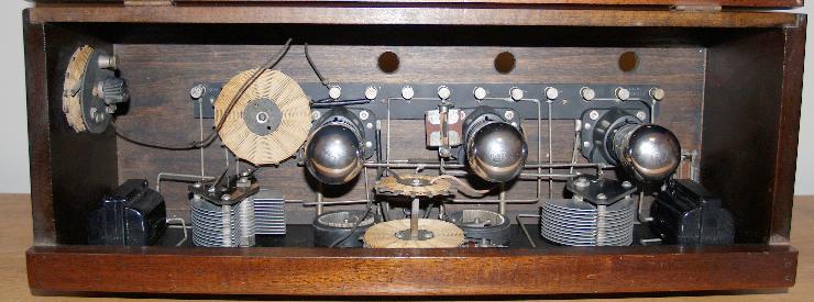
Below is a picture of the inside of the receiver.
The second tank circuit is tuned by another open air variable capacitor using the large knob on the right of the front panel. The RF signal from this tank circuit is coupled to the grid of the regenerative detector. The signal from the plate of the detector is fed back to its grid through the variable feedback or "tickler" control - the knob in the top center of the front panel.
Detected audio from the detector is coupled back to the grid of the first tube through an audio transformer. The first tube amplifies the audio along with the RF. The auido of the first tube is transformer coupled to the grid of the third tube. The third tube amplifies the audio and is direct coupled to an external speaker.
If headphones are used, the audio is taken off the plate of the first tube and the third tube is not used. Gain of the RF/first audio amplifier is controlled together with the gain of the second audio amplifier using the arrow knob on the left of the front panel. Gain of the detector is controlled using the arrow knob on the right of the front panel.