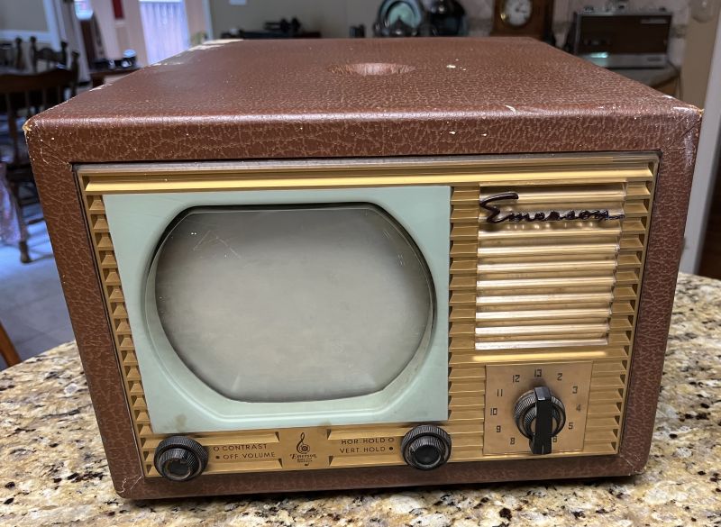
Emerson Model 600 Television Receiver
The television comprises 20 vacuum tubes. The CRT uses electrostatic deflection with no yoke. The television is rated at 0.98 Amps at 117 VAC.
The dimensions of the television are:
9 1/2 inches high, including the feet
13 1/2 inches wide
16 1/2 inches deep including the knobs
The televison is light-weight because it has no power transformer. The unit requires an isolation transformer for servicing.
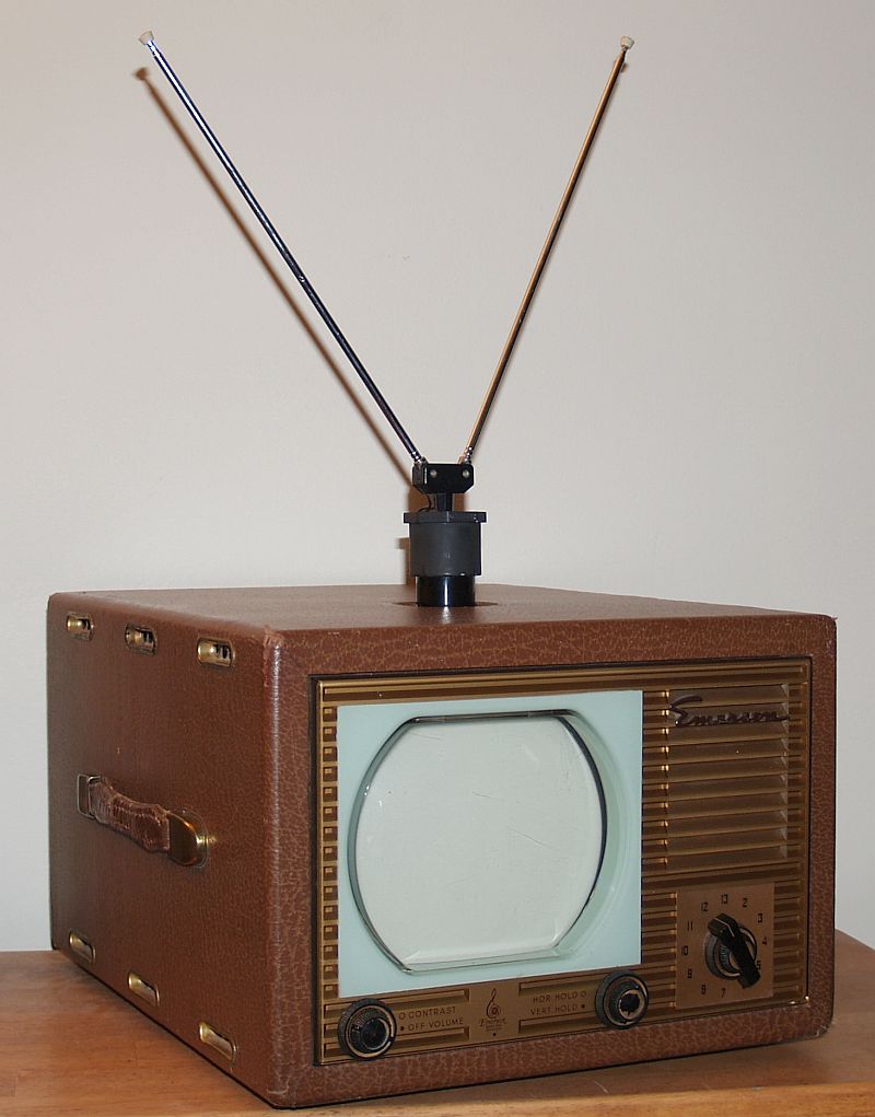
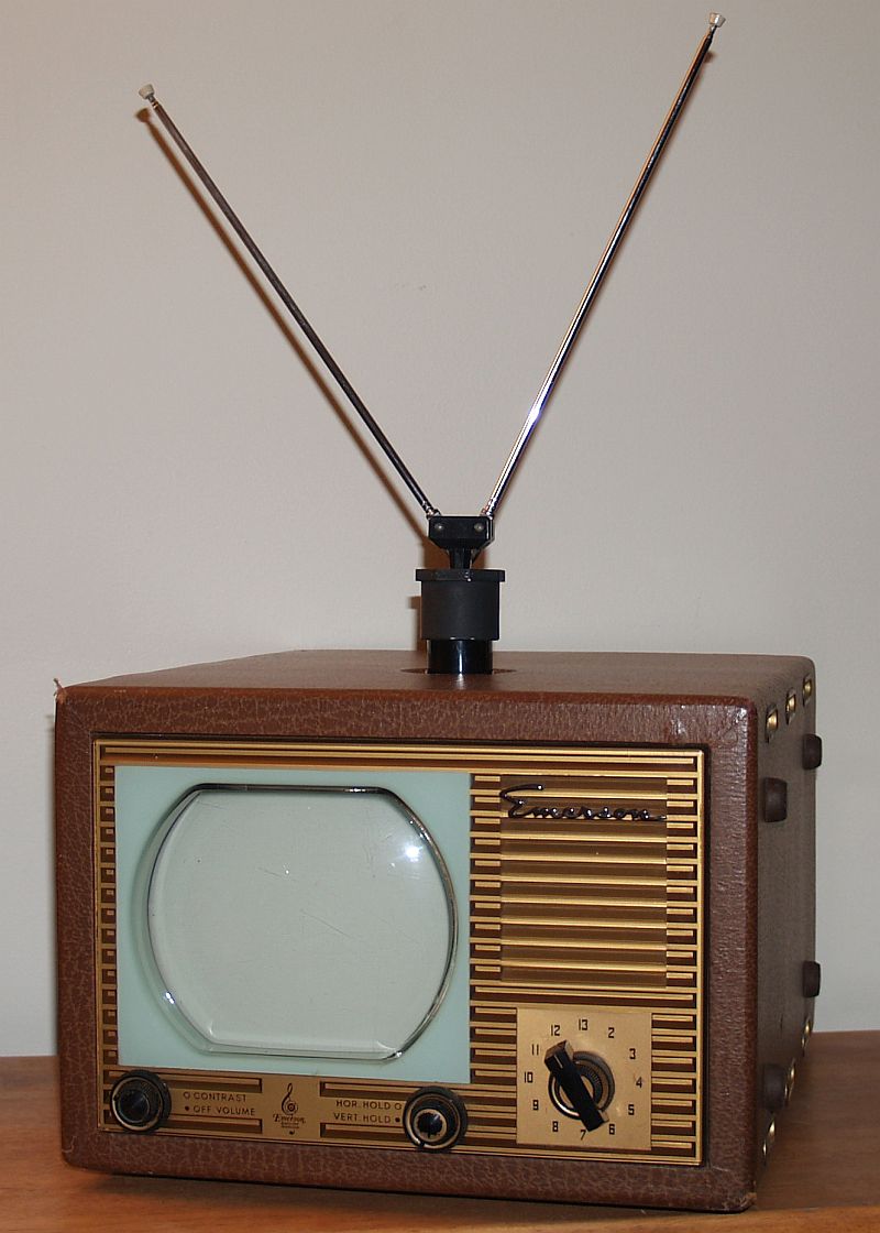
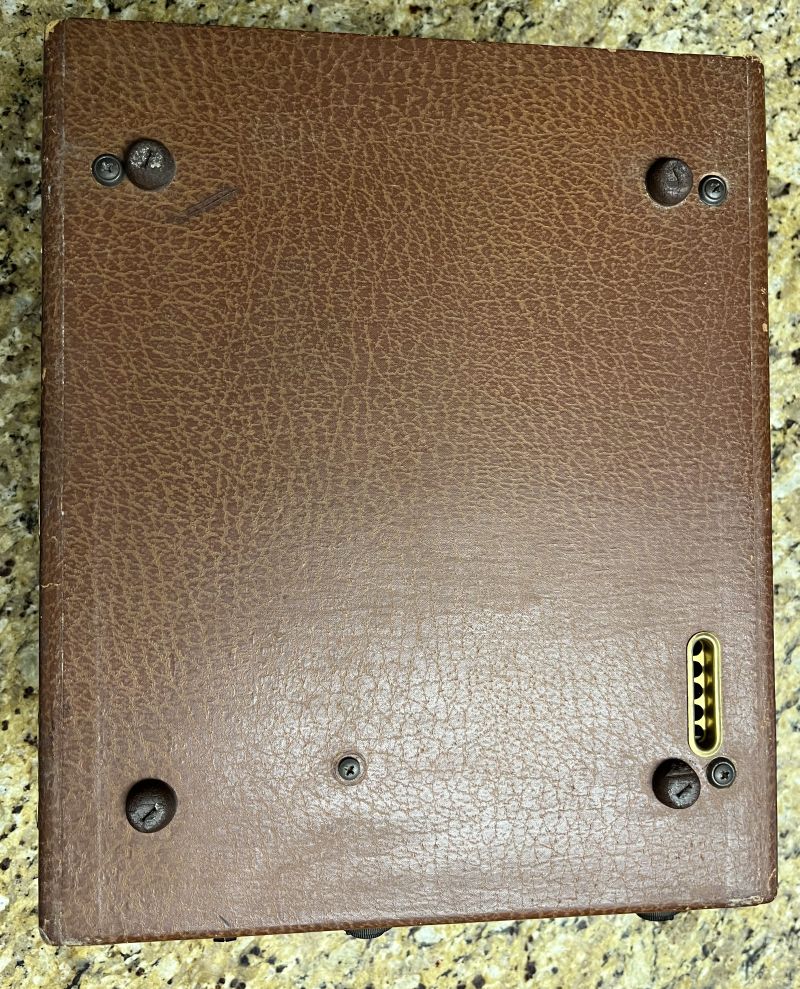
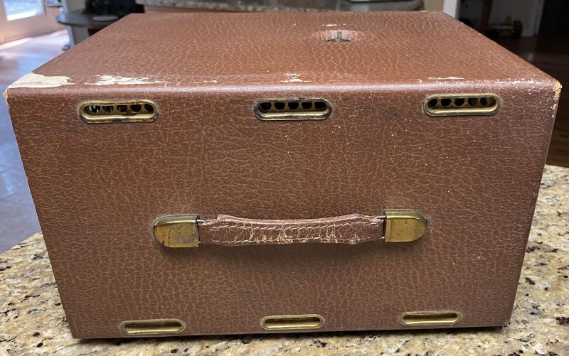
Below are pictures of the television when I received it.
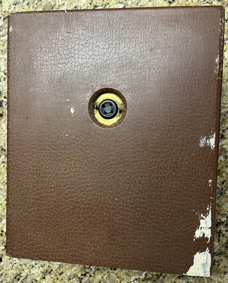
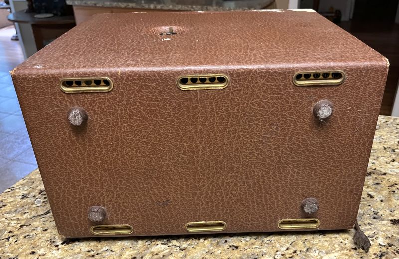
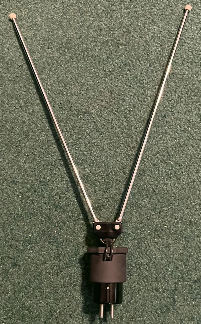
The top has has 4-pin tube socket for attachment of a removable "rabbit-ears" antenna. The original antenna is often missing. A short run of 300-ohm TV twin lead runs from the socket pins to the rear for connection to the antenna terminals of the chassis if the rabbit ears antenna is to be used. Otherwise, the internal twin lead is disconnected and an outdooor antenna is connected.
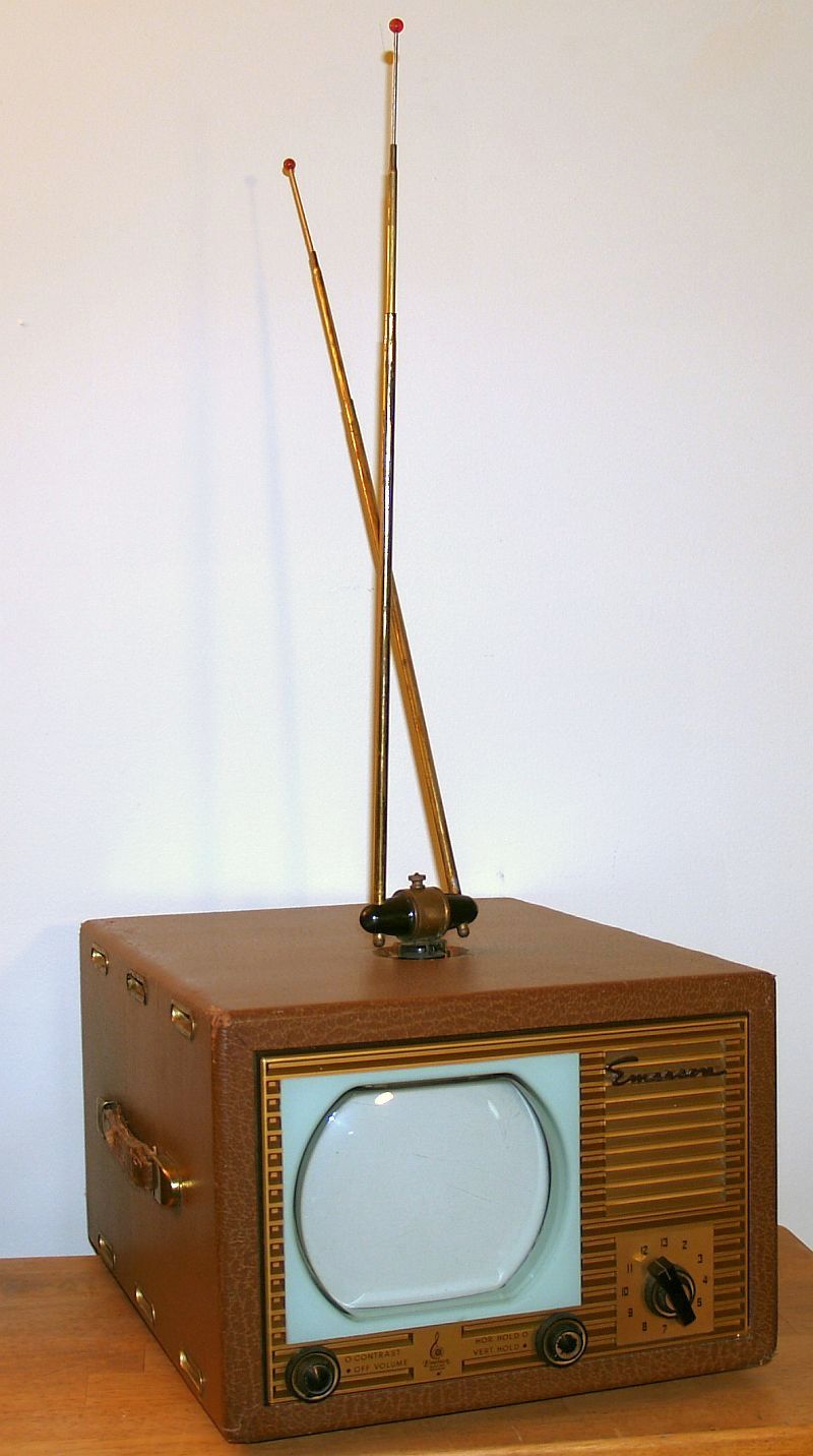
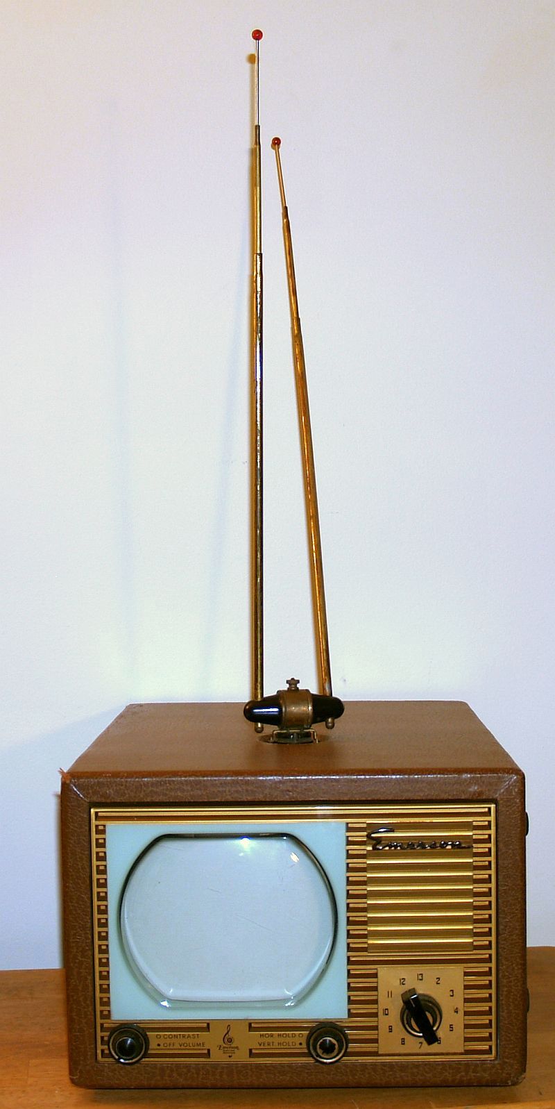
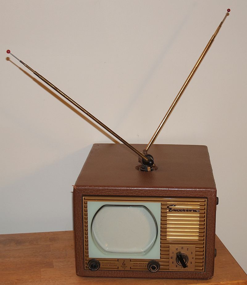
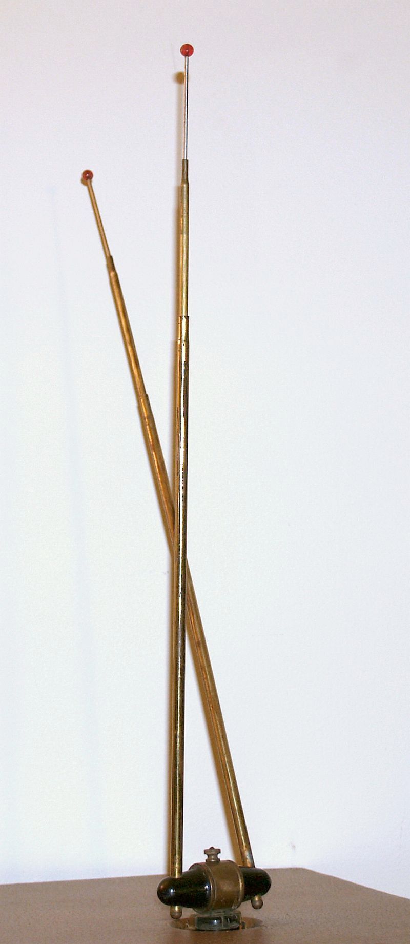
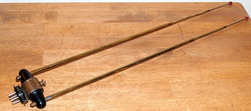
Below are pictures of the original antenna.
When I initially received the television, the origignal antenna was missing. I fabricated an antenna using a readily-available inexpensive rabbit-ears antenna, a 1 1/4 inch diameer PVC pipe plug, and a 4-pin tube base. The completed antenna is shown in the two pictures below.
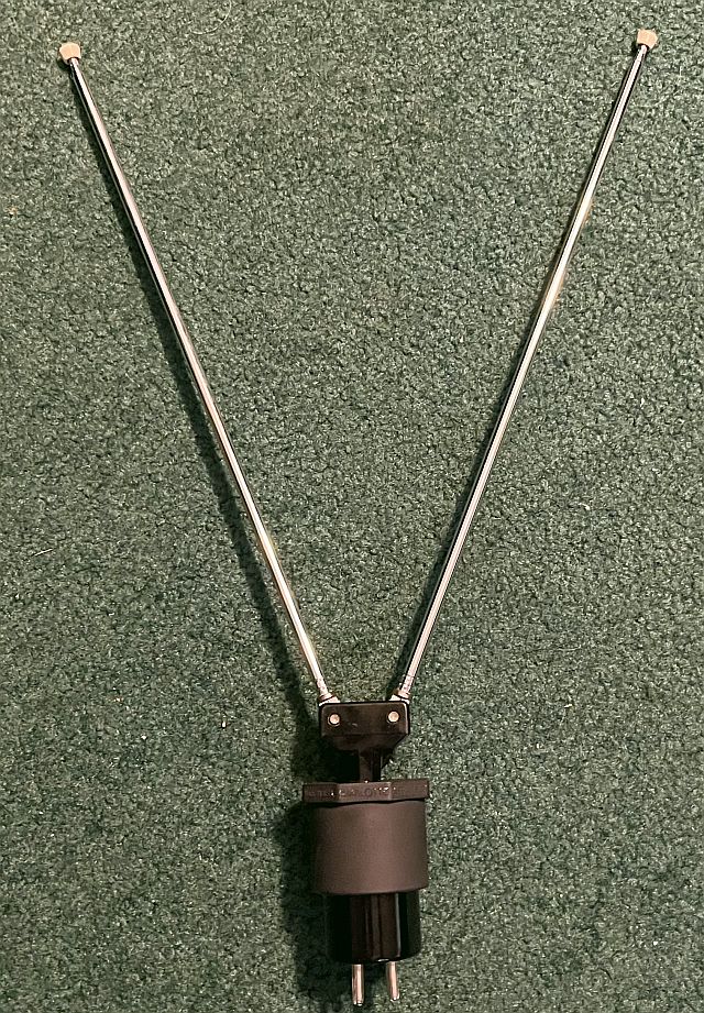
The 4-pin tube base fits snugly into the 1.35-inch inner diameter of the PVC pipe plug. The pipe plug is shown below.
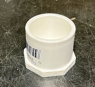
I drilled a hole in the top of the pipe plug to insert the antenna. The antenna has a key on its diameter and I had to cut a a small slit to accommodate the key. I painted the plug flat black. After inserting the antenna into the hole and aligning the boss with the slit, I used JB Weld to epoxy the antenna in place. I cut the antenna twin lead and attached two wires to each lead. The television socket uses all four pins, two pins for each of the two antenna leads. One lead connects to one of the large pins and the small pin adjacent to it. The other lead connects to the other large pin and the small pin adjacent to it. The antenna works quite well.
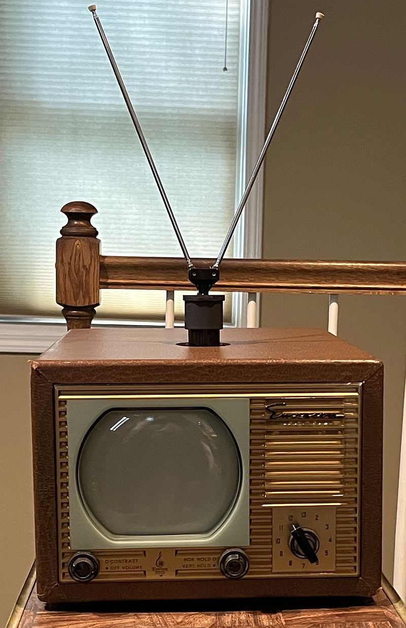
Later on at an auction, I found the original antenna.
The cabinet was in good good shape but has white paint splattered on it. I used a little paint remover and a hobby knife to lightly scrape the paint off. I rubbed brown shoe polish over the discolored parts to make ot look almost like new. All of the gold-colored vent inserts are present and not corroded - I left them as is. The handle is also in good shape.
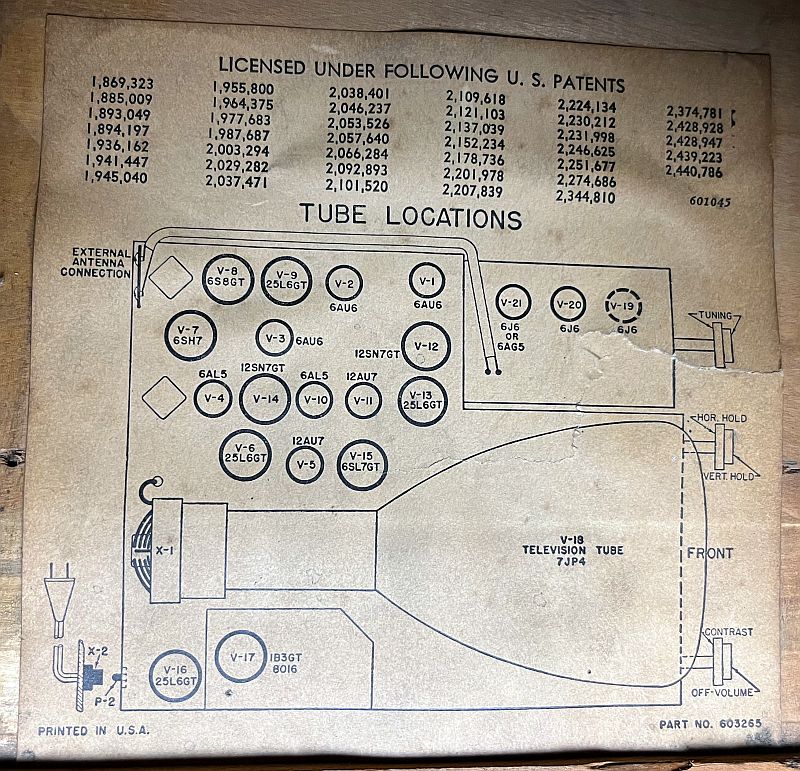
Below is a picture of the tube layout tag inside the cabinet.
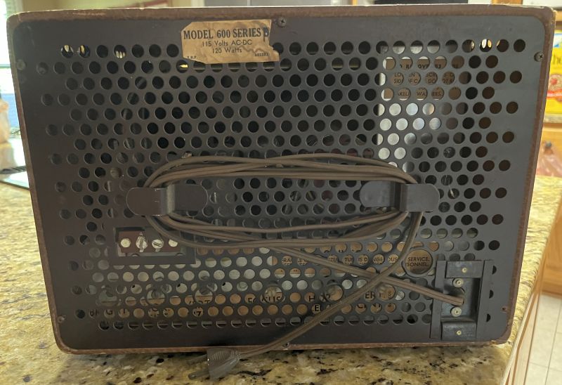
The television also has the original inspection tag attached to it as shown below.
The controls on the front panel include:
Off Volume Control/Contrast Control
Horizontal Hold Control/Vertical Hold Control
Channel Selector Switch/Sharp (Fine) Tuning Control
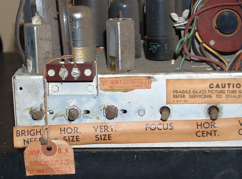
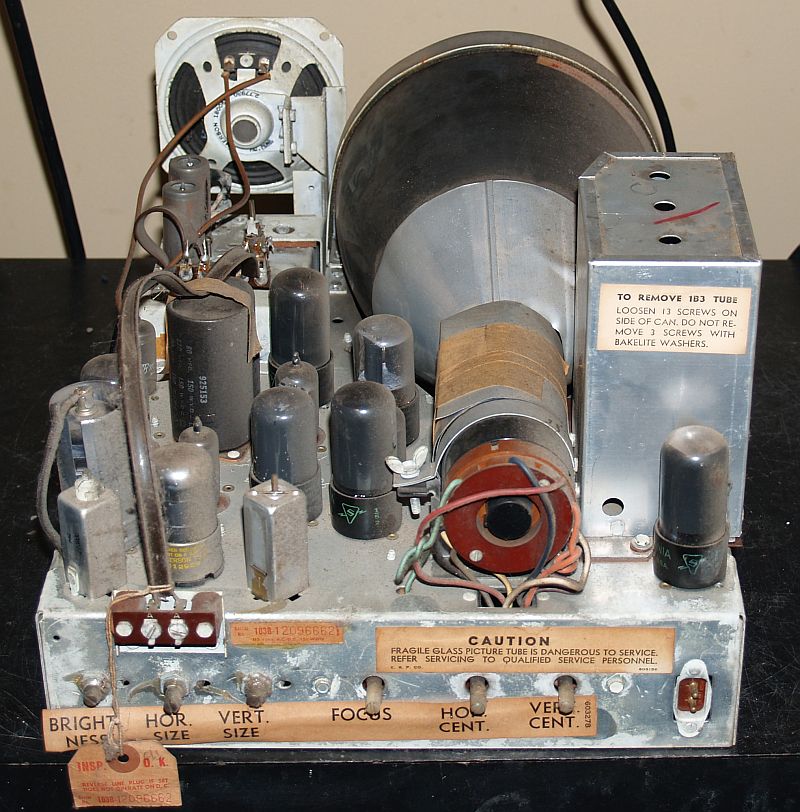
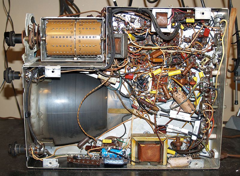
Below is a picture of the rear of the television with the cover removed.
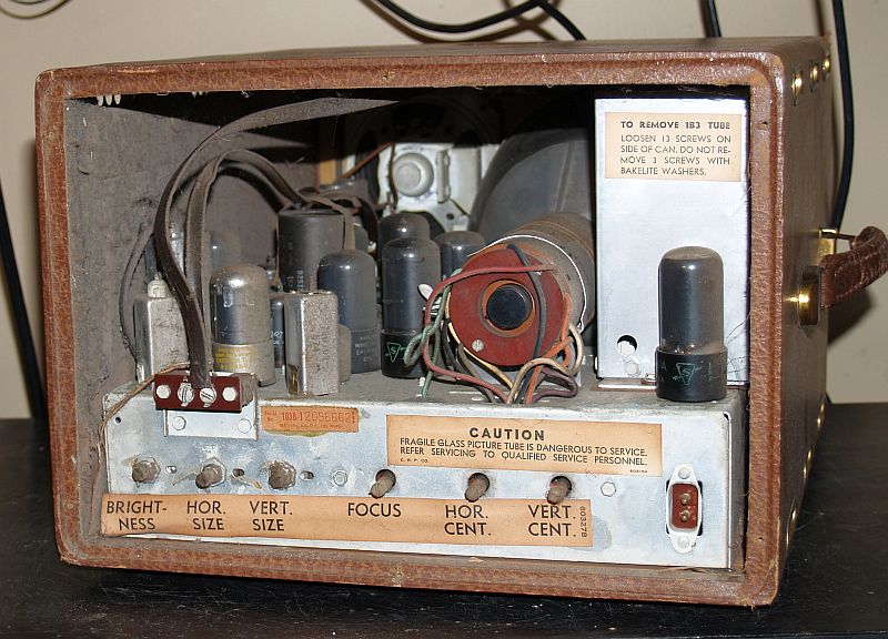
The adjustments on the rear of the chassis include:
Brightness
Horizontal Size
Vertical Size
Focus
Height
Horizontal Center
Vertical Center
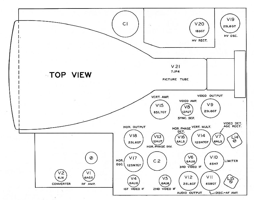
The picture below shows the tube layout as depicted in SAMS Photofact Folder 6 of Set 87, dated 3-50.
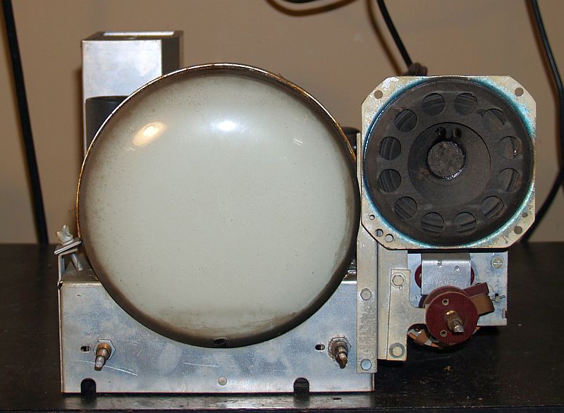
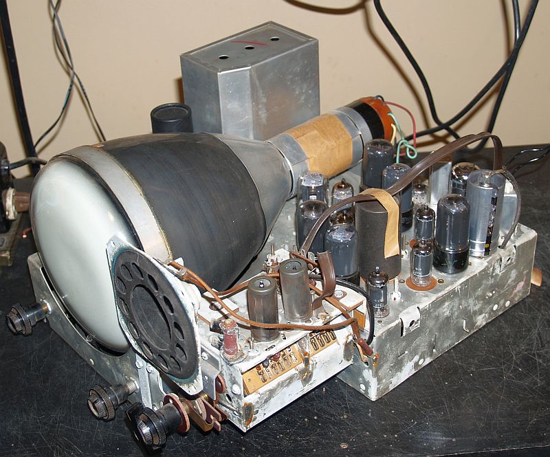
Below are pictures of the chassis removed from the cabinet. Note that there is not much dust on the chassis.The front of the picture tube has some grime on it.
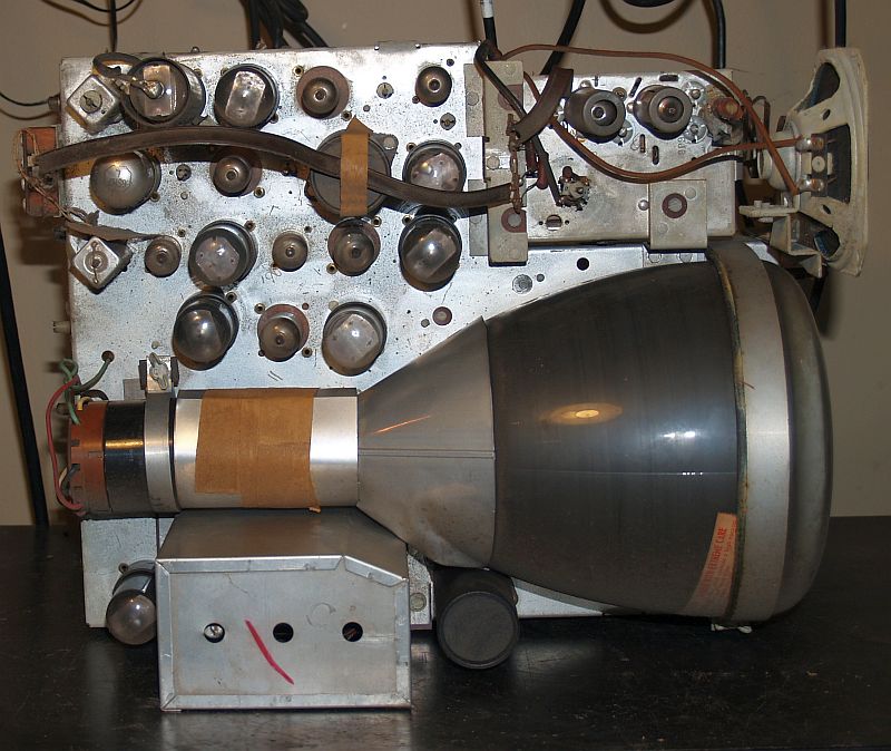
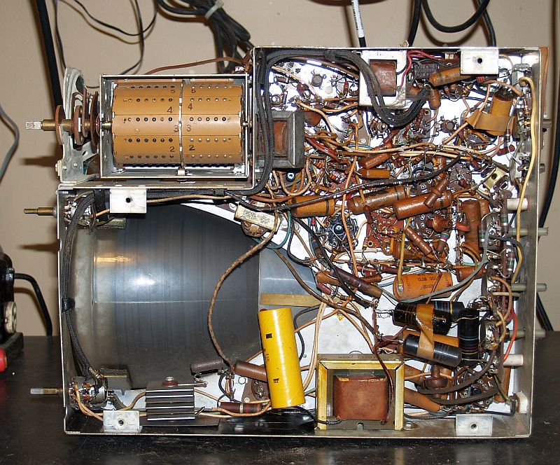
The electronics appear to be all original except for the large yellow electrolytic capacitor in the lower portion of the last picture above. This capacitor replaced one of the capacitors in the multi-element capacitor C1 during a previous repair long ago.
I replaced all of the wax paper capacitors in the television. In addition, I replaced all of the electrolytic capacitors but left the original chassis-mounted multi-element electrolytic capacitors in place to maintain the original appearance. I cut those capacitors out of the circuit.
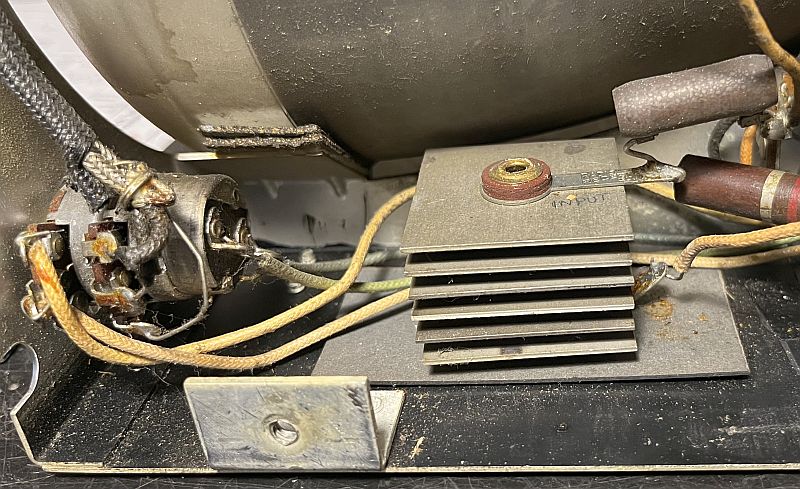
The picture below shows the original selenium rectifier. Resistive measurements indicated the rectifier to be bad. I replaced it with a 1N5408 silicon diode rated at 1000V and 3 Amps.
The picture below shows the bottom of the restored chassis with the new capacitors installed and the diode replacing the selenium rectifier. I used terminal strips to mount the diode and several electrolytic capacitors.
Changing out the wax paper capacitors was somewhat time-consuming. There were some that were difficult to get to as they were underneath other components. In a few cases, I had to remove the capacitors on top before replacing the ones underneath. I wrapped three of new electrolytic capacitors in thin cardboard to prevent shorting to other connections or to the chassis. Most of the resistors measured in tolerance. I replaced only one resistor, 470 ohms that measured 773 ohms.
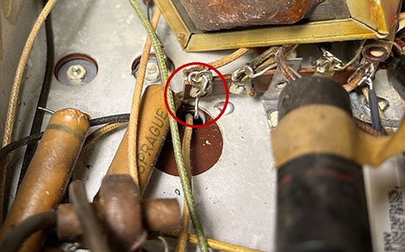
When replacing one of the high-voltage wax paper capacitors, I noticed one lead of the capacitor was never soldered during assembly. The unsoldered connection (but with the original capacitor cut out) is shown circled in red in the picture below.
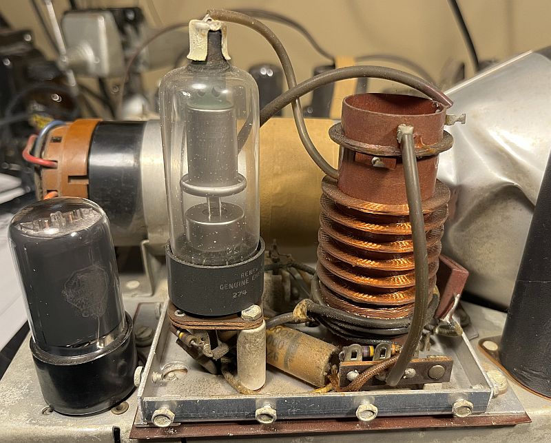
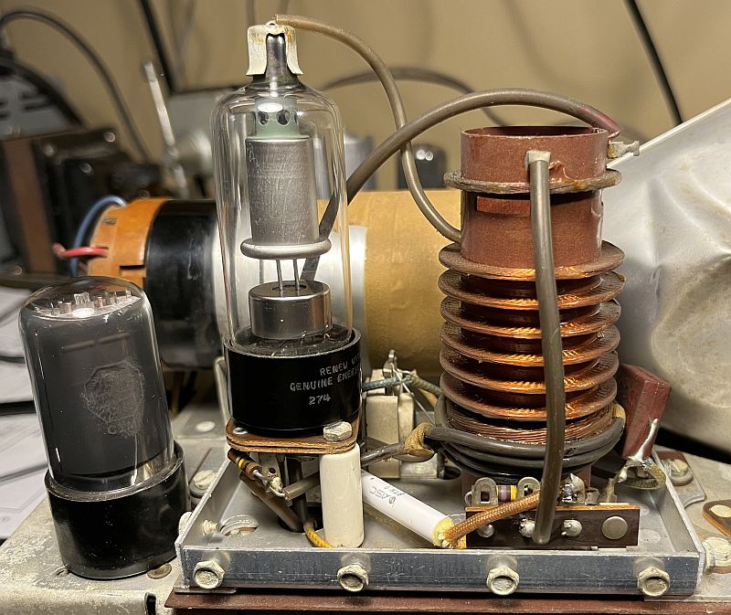
The pictures below shows inside the high voltage cage before and after restoration. The cage contained one high voltage wax paper capacitor that I replaced.
Below is a picture of the top of the restored chassis.
Many of the vacuum tubes were Emerson tubes, perhaps original to the television. Five vacuum tubes tested weak or bad on my TV-7U tube tester. I replaced them.
After restoration and replacement of the five vacuum tubes, I powered up the television using a variable transformer. The picture below shows the first raster displayed during this initial power-up.
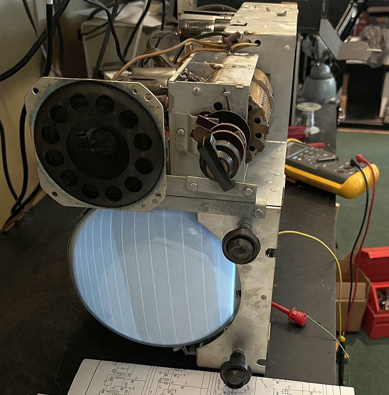
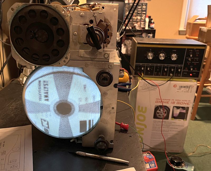
Note the raster is quite bright indicating the picture tube is good and shows a lot of life left. The picture below shows the first image received from my B&K Television Analyst.
Further testing indicated the receiver would not receive signals above Channel 6 and the images on the lower channels was not great, either. I replaced the 6J6 converter tube (that tested good) with a new old stock tube. The higher channels would now receive signals, but the video was not good and the audio was distorted. Measuring the local oscillator frequency on several channels with a spectrum analyzer indicated the local oscillator frequency was incorrect. The fine tuning would not properly tune in the signal. The tuner has a factory adjustment for trimming the local oscillator frequency. It was turned almost all the way in to its lower limit. While viewing a Channel 3 television signal with video and audio, I backed out the adjustment and the Channel 3 image and audio greatly improved. I tuned the television to Channel 12 with the same television signal with video and audio and adjusted the Channel 12 local oscillator coil to produce good video and audio. The only thing I can conclude is that at sometime in the past, someone adjusted the factory trimmer to improve some channel reception and possibly adjusted other individual channel coils. A any rate, the television works well now.
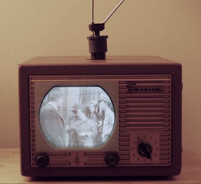
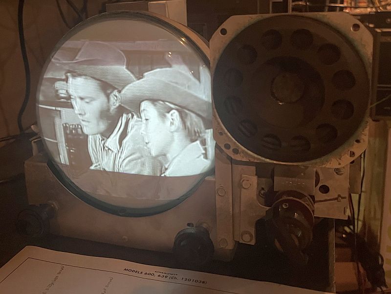
Below is a picture of a television program (The Rifleman) being received.
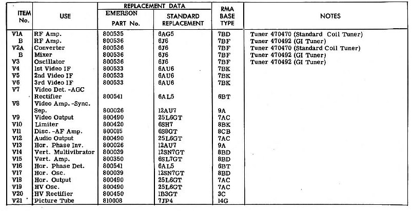
Below is a list of the vacuum tubes in television from the SAMS Photofact. The listing covers two different tuner models that may be installed. There is only one 6J6 converter tube (V2) in the standard coil tuner installed in my television. That single tube functions as a converter, mixer, and oscillator. For the GI tuner, SAMS Photofact lists these functions as two vacuum tubes V2A and V3. The tube layout tag inside the cabinet shown earlier also lists two 6J6 converter tubes as V-20 and V-19, but V-19 is outlined with a dotted line, indicating it may or may not be included.
Below is a picture of the televison operating and a video of it receiving an episode of the Andy Griffith Show.