The bandswitch rotates a dial drum to display one of the six tuning ranges. the tuning ranges are:
0.54 - 2.0 MHz (covers the 160m ham band)
3.5 - 4.0 MHz
7.0 - 7.3 MHz
14.0 - 14.35 MHz
21.0 - 21.45 MHz
28.0 - 29.70 MHz
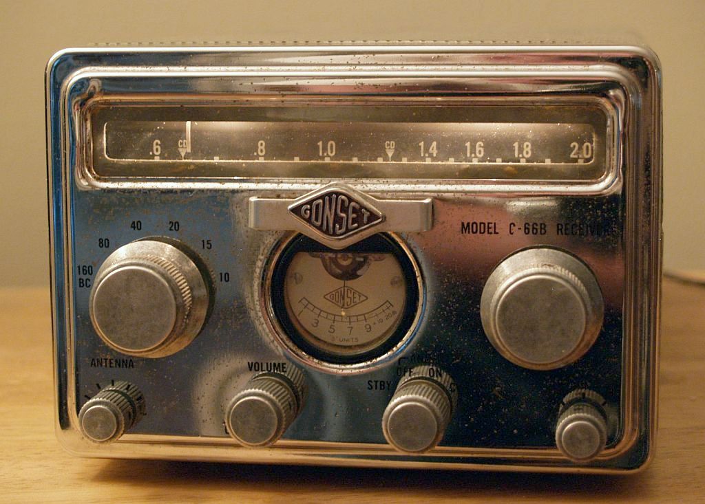
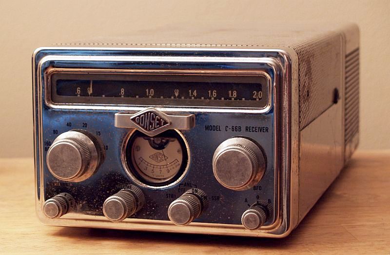
When I purchased this radio at a hamfest (amateur radio convention), it was in reasonably good shape. The chrome front face is a little pitted but looks reasonably good. But it had some performance issues.
The first issue was the ball bearing reduction dial drive shaft would not stay in place. I removed the drive assembly and after much study, I could not figure out how the shaft was captured in the planetary drive assembly. The figure below shows all of the parts after I removed it. I could not determine what part might be missing that would secure the shaft in the assembly.
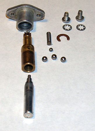
A direct replacement drive would be impossible to find, so I decided to eliminate the planetary drive feature and drill and tap a hole for a 4-40 setscrew. This approach seems to work fine and the absence of the planetary drive feature doe not seem to impair use of the radio.
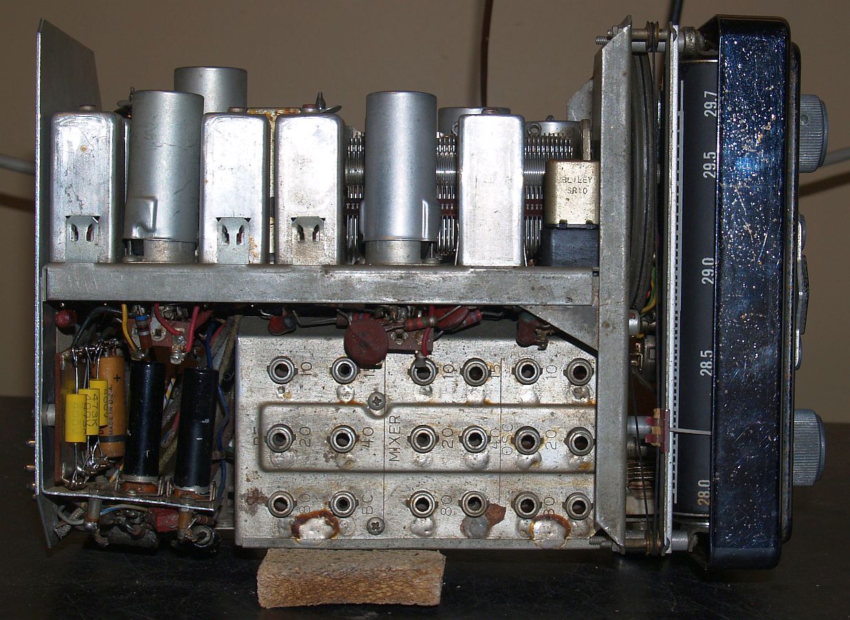
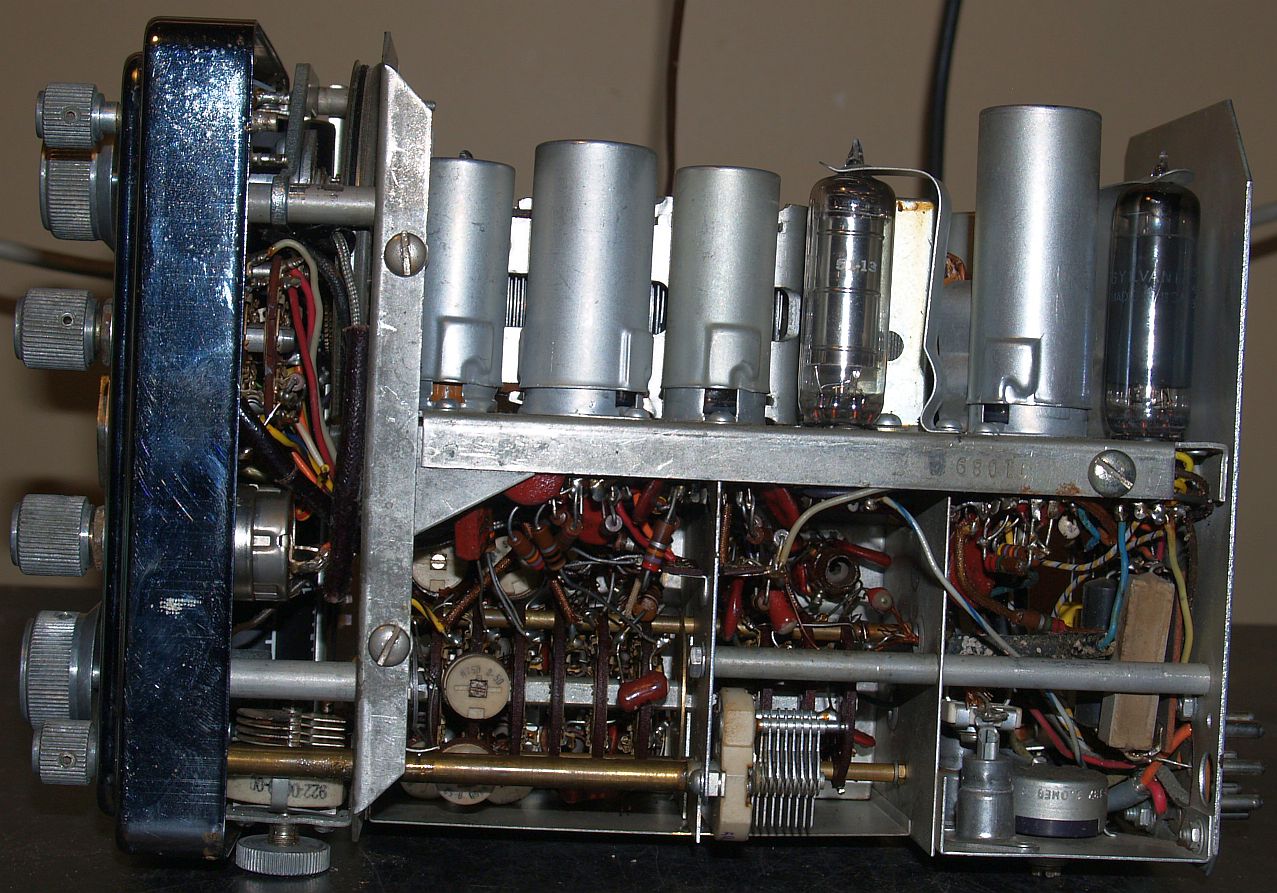
The faceplate of the radio indicates that it is a "B" version, but this example radio is inconsistent with what information I could find online for the "B" version. I think the "B" version primarily added an additional IF stage for better noise performance on the higher bands. My radio does not have a second IF stage and a second IF stage clearly was never installed. In the place where the second IF stage would be installed is a plate containing two subminiature vacuum tubes. These two tubes are a 6021 (dual triode) and a 5896 (dual diode). These two tubes can be seen in the picture below on the left-hand side:
Below is a close-up of the two subminiature tubes.
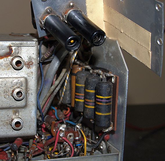
The two subminiature tubes are the black cylindrical objects with the 6061 being the one toward front of the radio and the 5896 next to the rear of the chassis. The tubes contain a black metal shield over each tube. Close examination of this "modification" suggests that is a factory modification as the construction technique is quite good. Close examination also revealed that one leg of the 1M resistor (R27) had been cut. The cut resistor can be seen the picture below:
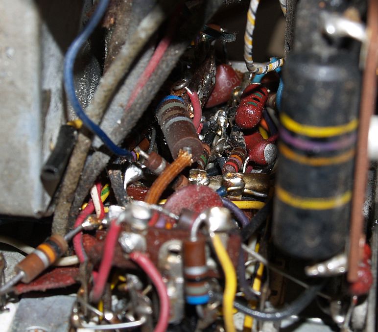
I did trace out the two-tube modification circuit and it appears the dual-diode may drive the dual triodes to "squelch" the audio during noise bursts. I did not trace to determine where the modification circuit connects into the main radio circuit.
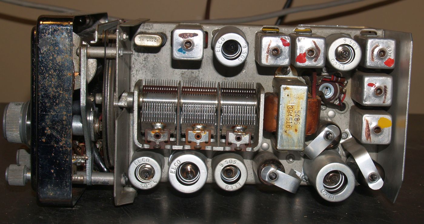
There are other differences in this example from what I have seen online. This example does not have a phone jack for headphone use. There is a potentiometer where the phone jack is located on other examples I have seen. The picture below shows the area where the phone jack would be along side two Motorola mobile antenna jacks.
The hole between the two antenna jacks is for adjusting the antenna coupling capacitor that couples a broadcast antenna to the main receiver input.
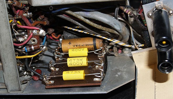
I changed out the three Sprague paper molded case "black beauty" capacitors before bringing up the radio on with a Variac. These capacitors are known to explode and I did not want to clean up the mess. The picture below shows the new capacitors installed.
Of course, the radio did not play. I first checked out the audio amplifier, detector, and IF stages before looking at the radio front end. It turned out the radio had two bad tubes - the 6C4 first oscillator and the 6U8 mixer-buffer. After replacing these tubes, the radio did play, but it would not receive CW or SSB. It turns out the BFO frequency was significantly low in frequency and I had to retune the inductor that is as part of the oscillator tank circuit.
Below are other pictures of the radio internals.
Below is the bottom of the radio.
Below is the top of the radio.
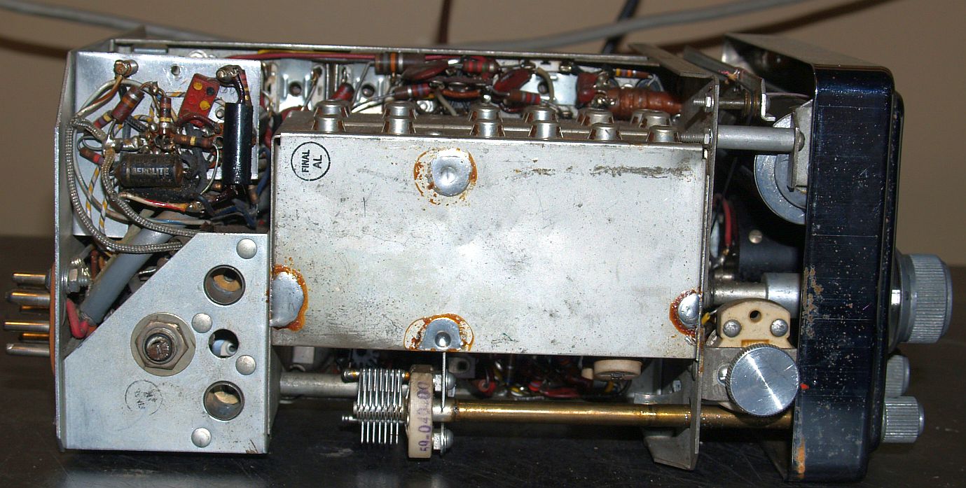
Below is he left side of the radio.
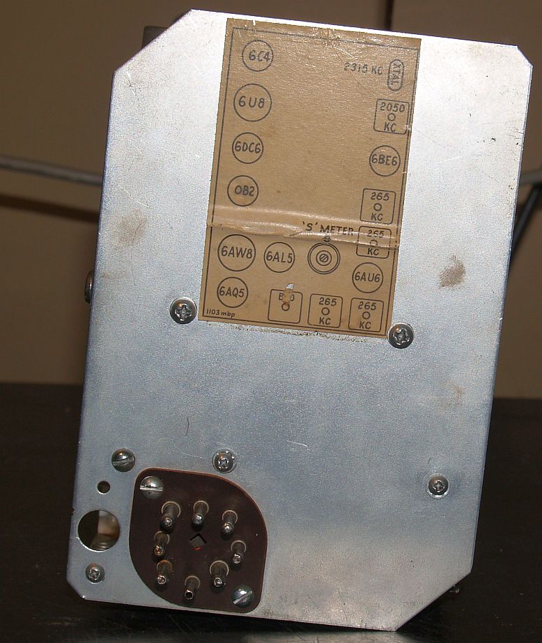
Below is the rear of the radio.
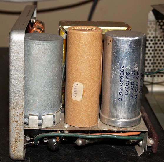
The radio came with the Model 3069-12 power supply attached. The power supply can run off 12 VDC or 115 VAC, depending on how one wires up the power plug. The power plug was missing, but fortunately, I found one at the same hamfest. I wired the plug for 115 VAC. The picture below shows the internals of the power supply. Below is a picture of the rear of the power supply.
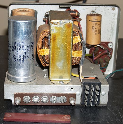
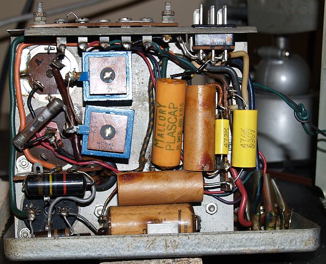
Below is a picture of the bottom of the power supply before I replaced the "black beauty" capacitors. Note that the power supply contains two selenium rectifiers. I did not replace them.
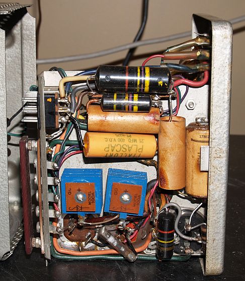
The picture below is the left side of the power supply.
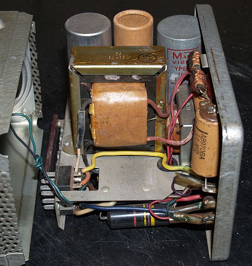
The picture below is the right side of the power supply.
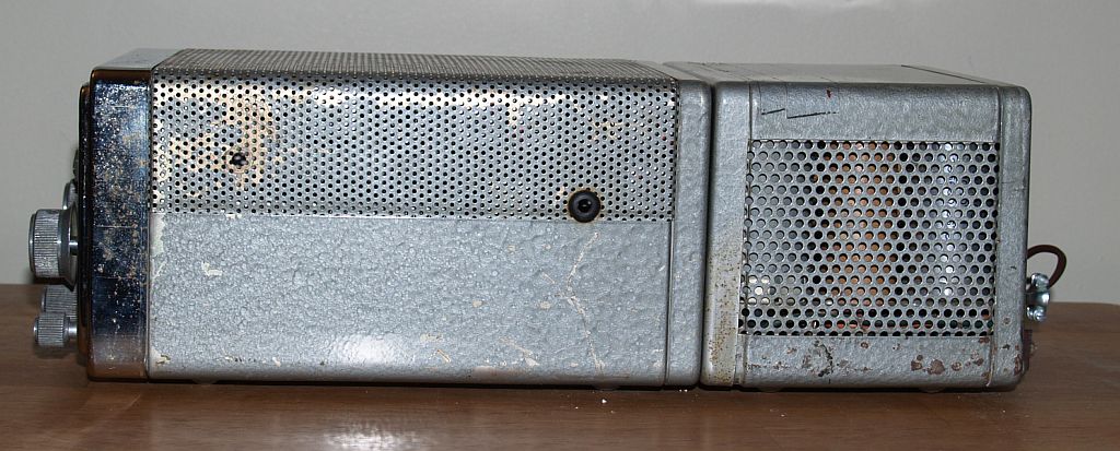
Below is a picture of the left-hand side of the radio with the power attached to the rear.
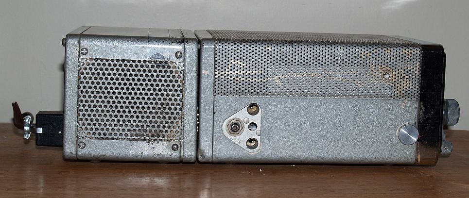
Below is a picture of the right-hand side of the radio with the power supply attached to the rear.
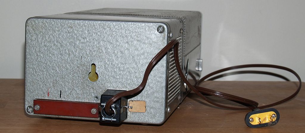
Below is a picture of the rear of the radio with the power supply attached. The power cord I made is attached.
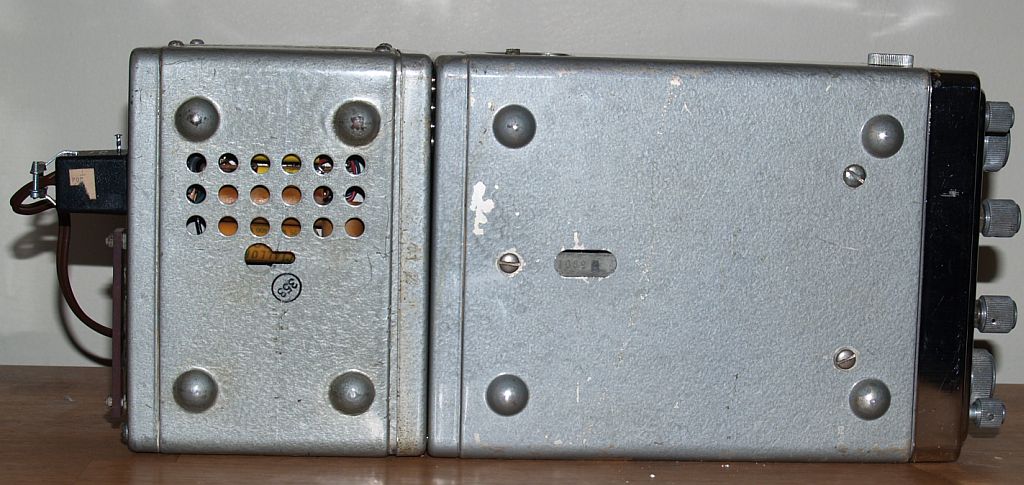
Below is a picture of the bottom of the radio with the power supply attached.
Below is a picture of the radio on and tuned to WSM in Nashville, TN.