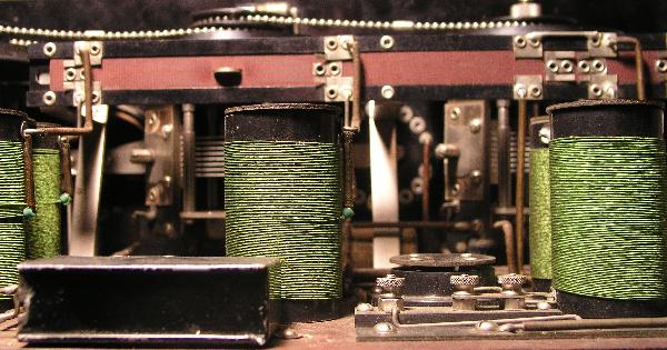
Below is a view of the inside of the radio.
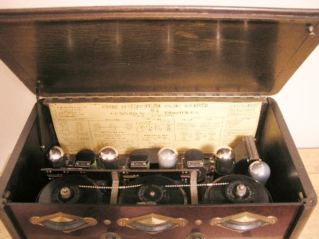
The radio has a unique design of the tuning condensers (capacitors) that makes the tuning quite linear across the dial. With this design, the spacing between radio stations is approximately equal from the low end to the high end of the dial which makes it easier to tune in stations. Tuning of the radio is divided into two bands for the Standard AM Broadcast band to spread out the tuning. This radio is quite sensitive easily receiving many stations with modest antennas.
The radio has two tuned RF stages. The detector stage is also tuned making a total of three tuned stages. All stages are tuned simultaneously using the center "Master Dial". The "Left" and "Right" dials are tuned simultaneously with the "Master Dial" because they are connected to the "Master Dial" with a chain similar to the ball chains used on modern lamps. (This chain is often missing on these radios, but I was fortunate that mine still has the chain in place) The chain fits fairly loosely so there is a "Vernier" control beneath each dial that can be used to fine tune and peak each stage once they are tuned near the desired station. A thumb-nut on top of the "Left" and "Right" dials loosens the pulleys to allow those two dials to be "Synchronized" with the "Master Dial." This synchronization is probably not performed too often. The instructions say you can loosen one of the thumb-nuts and have two-dial control instead of three dial control.
The radio has a "high-low range switch" coupled to the center "Master Dial". To place the radio in the "high range" you move the "Master Dial" past 100 as far as it will go. This action moves a lever inside that changes taps on the three "Binocular" coils. To place the receiver in the low range, you move the "Master Dial" below zero as far as it will go and this action moves the lever described above in the opposite direction. As an alternative, you can reach inside the radio and move the range switch manually. The picture below shows the range switch. The range switch is the reddish colored bar at the top of the picture. The bar moves back and forth. The silver colored tab sticking through the bar at the top left center moves the switch under control of the center "Master Dial."
There is a table on the instruction sheet that the manufacturer calibrated dial readings verses wavelength for the low and high ranges. The high range covers from about 175 m (1,700 kc) to about 315.6 m (950 kc). The low range covers from about 263 m (1,140 kc) to about 526 m (570 kc). Therefore this radio has two ranges to cover the entire Standard Broadcast AM band.
The three tuned circuits use the "Binocular Coils" (Grebe trademark). These unique coils are shown in the picture below and allow the RF stages to have significant gain without oscillating.
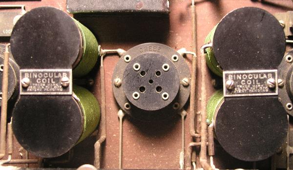
The tube sockets are somewhat unusual in that all have spring-mounted tops to reduce sensitivity of the tubes to microphonic vibrations. The tubes "wiggle" if you tap on the radio case. You can see one tube socket in the picture above.
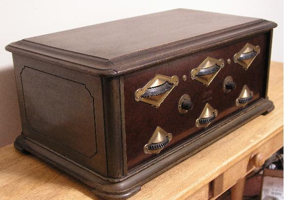
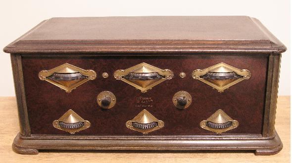
Below is a closeup of the front panel of the radio. The escutcheons are all gold plated.
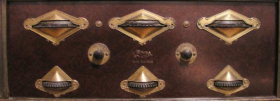
There is a 6-position "Colortone" (Grebe trademark) in the center left of the front panel. This control adjusts the treble for the listener's preference. The volume control is located on the center right of the front panel and adjusts the filament voltage for the tubes.
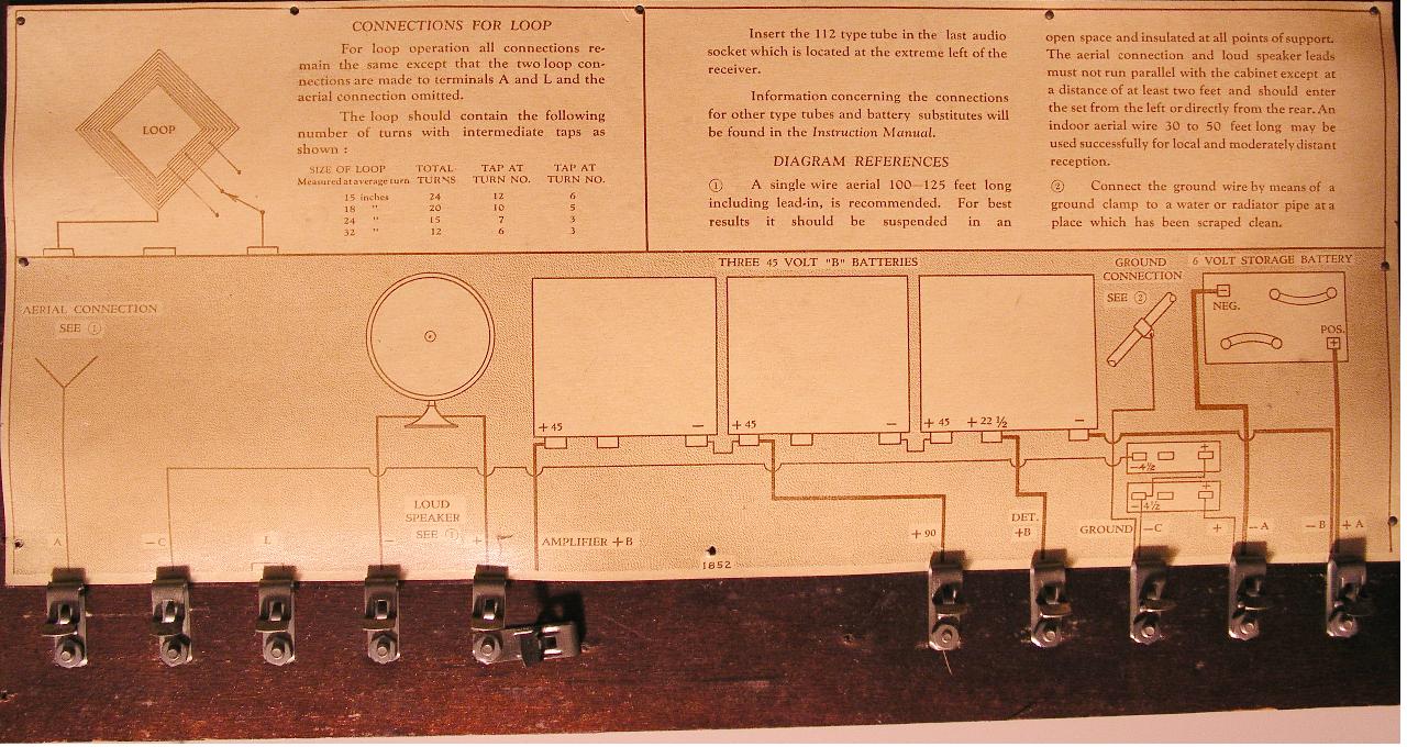
Located on the inside back panel of the radio are instructions for operating the radio. This instruction sheet is shown below. On this sheet you can see the calibration for the high and low ranges that were handwritten by a worker at the factory.
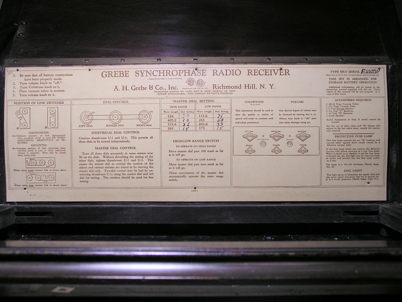
The radio is designed to use either an indoor loop antenna or an outdoor long wire aerial. There are two "jumpers" that you have to position to select the type of antenna in use. The "aerial" jumper can be positioned to increase selectivity as stated on the instruction sheet above.
The radio has a #19, 1.5V incandescent lamp in series with the B+ to protect the radio, batteries, and vacuum tubes from shorts caused by a defective vacuum tube. This feature is unusual from my experience with 1920's battery sets. The radio also has a Type T-3, 6V incandescent lamp that illuminates the "Master Dial" and also gives a visual indication that the radio is on. This illumination is at the expense of consuming A-battery energy! Details of the lamps are included on the lower right of the instruction sheet.
Another instruction sheet is attached to the bottom of the radio. This instruction sheet, shown below, describes how to connect up the batteries. The bottom of the radio also contains the Fahnstock connectors for connecting the batteries and the speaker.
The radio requires the following voltages for operation:
| DC Voltage (V) | Function |
| +5 | Filament (A+) |
| +22.5 | Detector B+ |
| +90 | RF and 1st Audio B+ |
| +135 | 2nd Audio B+ |
| -4.5 | from -A to GND |
| -9 | 2nd Audio C- |
When I received the radio, all of the tubes were dislodged from their sockets and two were broken. The spring-loaded sockets apparently "threw" the tubes around inside the radio. It took some time to pick out all of the glass. However, I am now able to see the tube elements inside the tube. See my other page for details of the tube elements of an Eveready Raytheon ER201A and a Cunningham CX-112-A tube.
The broken tubes were no great loss because I was told they were duds anyway. However, one 112A tube included was good! So I guess I came out ahead.
The only problem with the radio was a open secondary winding of the second audio transformer (the small one). I disassembled the transformer, replaced the coil with a modern replacement, and reassembled the transformer. Pictures of the process are presented below.
The original transformer after removal of the housings is shown below.
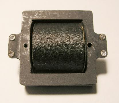
Connections are made to the four eyelets mounted on the square cardboard. I marked secondary with an "S" and primary with a "P".
The repaired transformer before replacing the housings is shown below.
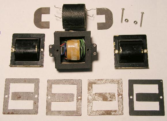
The iron core of the transformer comprise several layers of "E"-shaped iron sheets, shown at the bottom of the figure. The iron "E-sheets" are installed in alternating fashion - one layer has the E facing left; the next layer has the E facing right. I noticed during disassembly that the original assembly did not follow this technique - apparently some stuck together and the assembler did not notice that. I really does not affect the performance, though. The winding assembly I used had a slightly smaller hole than the original, so I could not use all of the iron sheets. I could not get 3 of them in, so I left them out. The original transformer also included 2 cardboard insulators (one is shown on the lower right) and I could not get one of them in, so I left it out. The performance was not affected by leaving the above items out. I did place the two "C-shaped" paper insulators (shown at the top on either side of the original coil) back in but in the new configuration, they were not really needed.
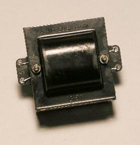
The picture below shows the completed and repaired transformer. After using black paint to touch up scratches I made during disassembly, it looks like the original except for the screws holding it together. The original used a long rivet that I had to drill out. I replaced the rivet with two 4-40 screws and nuts. I made a special cardboard spaced to compensate for the iron sheets and original cardboard sheets I left out. The transformer needed to maintain the same external dimensions in order to be reinstalled in the radio.
 >
>
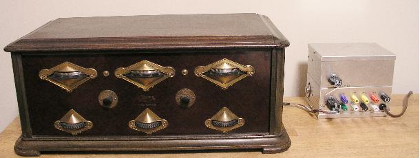
I connected the radio to a dc power supply I made. I did not use the 135V for the B+ on the last audio output stage, nor did I use the additional -4.5V grid bias for this tube as called for in the instructions shown above. I ran the output off of +90V and used a -4.5V bias for the tube. The radio works quite well and receives many stations across the dial. The radio is shown below with my homemade power supply. I have attached "Cinch Jones" plugs to the power cables so I can quickly connect the radio to the power supply.
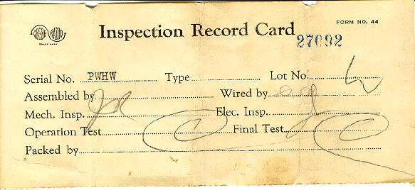
Below is the Inspection Record Card that came inside the radio.