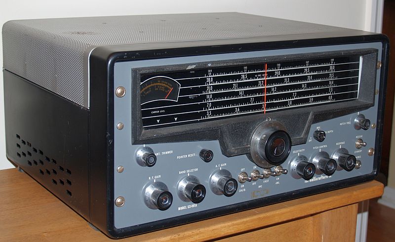
Each amateur band has an individual calibrated dial scale. Tuning is facilitated by a 10.5-inch long slide rule dial with dial graduations at every 5 kHz in the 80, 40, 20, and 15 meter bands. On the 10 meter band, dial graduations are provided every 25 kHz. Dial graduations are provided every 50 kHz in the converter band. The converter band (Band 1) is calibrated for both the 2 (144-148 MHz) and 6 (50-54 MHz) meter bands. Only the calibrated dial scale that is in use is illuminated. When the 10-MHz WWV "band" is selected, all of the bands are illuminated. The radio receives AM, CW and SSB signals.The upper or lower sideband (in both AM and SSB modes) is selectable by a front panel control.
The radio is a double conversion superheterodyne receiver on all bands that includes an an S-meter, variable IF selectivity, selectable SSB, selectable fast attack/slow release/on-off AGC circuit, a product detector, a noise limiter, and antenna trimmer. Receiver selectivity is variable in five steps: 500 Hz, and 1, 2, 3, and 5 kHz at 6-dB down.
The S meter is calibrated in microvolts, "S" units from 1 to 9, and in dB above S9 to +80 dB. The S meter is active when the AVC is turned off.
The radio does not have an internal speaker. There is a screw-terminal strip on the rear of the radio for connecting the wires of an external 3.2-ohm speaker. Provisions are also included for a 500/600-ohm line or speaker. There is also a front panel jack for headphones.
The radio is quite heavy, weighing about 70 pounds. Power consumption is 115 Watts.
The controls on the front panel include:
| Main Tuning Knob |
| Audio Frequency Gain control |
| RF Gain control |
| AVC On/Off - Automatic volume control on/off |
| AVC Slow/Fast - Automatic volume control fast decay or slow decay |
| ANL On/Off - Automatic noise limiter on/off |
| Response - Radio On/Off, SSB Upper, SSB Lower, AM Uppoer, AM Lower |
| Selectivity - IF selectivity: 0.5, 1, 2, 3, 5 kHz |
| Band Select - Tuning range selector |
| Pitch Control - Product detector oscillator tuning |
| Notch Depth - Turns on notch filter and adjusts depth of notch |
| Notch Frequency - Tunes the notch from approximately 50 kHz to 54 kHz |
| Ant. Trimmer - Antenna trimmer |
| Pointer Reset - Pointer position control; used to calibrate dial with crystal calibrator |
| Calib. On/Off - Crystal calibrator function switch |
| Receive/Standby - Standby-Operate switch |
Below is the tuning range of the receiver:
| 80 Meters | 3.5 - 4.0 MHz |
| 40 Meters | 7.0 - 7.3 MHz |
| 20 Meters | 14.0 - 14.4 MHz |
| 15 Meters | 21.0 - 21.5 MHz |
| 10 Meters | 28.0 - 30.0 MHz |
| 6 Meters | 50 - 54 MHz (with converter) |
| 2 Meters | 144 - 148 MHz (with converter) |
| WWV | 10.0 MHz with calibrator |
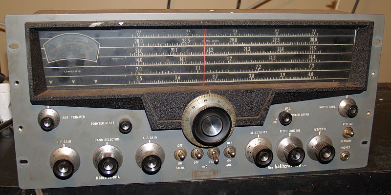
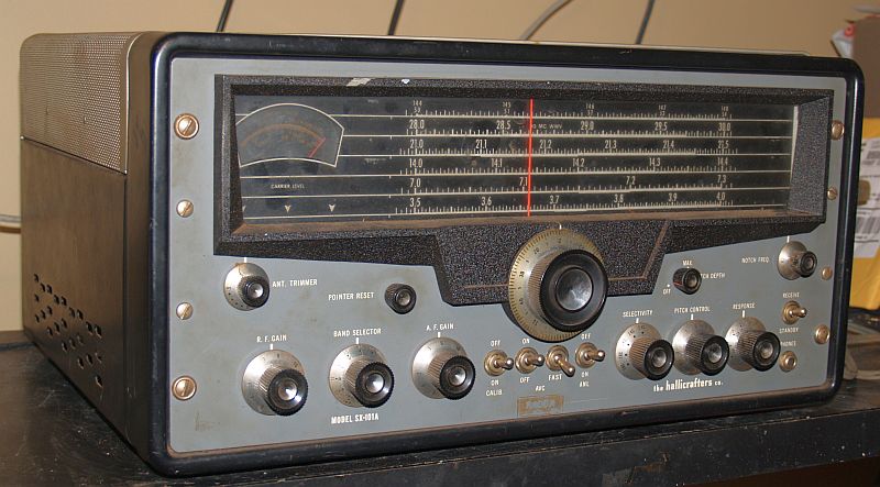
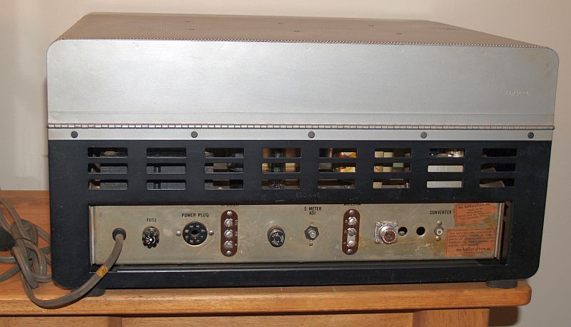
When I received this radio, it was quite dirty with dirt on all of the knobs. The front of the radio was quite grungy and there was dirt on the inside of the glass dial. Pictures of the radio as received are shown below.
I used water with Clorox and Comet to clean all the knobs and the front of the radio. I used the same cleaners to clean the metal cabinet and I used a hose to wash the cleaners off the cabinet.
I had to remove the front cover to completely clean the dial and the signal strength meter. The picture below shows the radio with the cover revomed.
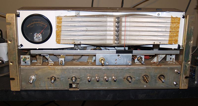
Removing the front cover is a chore as all 15 knobs must be removed. The set screws for all of the knobs require "Bristol" spline key wrenches to turn them. Two center screws on each side of the front panel hold the front panel to the chassis. These four screws did not have washers.
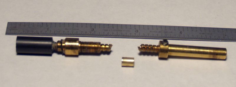
When I removed the front panel, I discovered the shaft for the notch filter tuning ferrite slug was broken. I suspect it broke when someone carelessly removed or reattached the front panel. The shaft passes through a fiber collet that is inserted into the front panel. The fit is tight, and the panel is heavy and the weight of the panel on the shaft could easily break it.
I was able to repair the shaft by making a collet from brass tubing with an internal diameter that just fit over the shaft with a little hammering. The figure below shows the broken shaft and the 1/4-inch long collet used to repair the shaft.
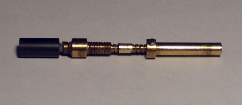
I slipped the collet on one end of the broken shaft and spread JB Weld epoxy inside the collet and then slipped the other end of the shaft inside the other end of the collet. The picture below shows the repaired shaft.
The notch coil without the ferrite slug and the metal shield over the coil can be seen below:

When the shaft was repaired, I had to realign the filter circuit as the shaft is allowed to turn only about 300 degress. Thus, the ferrite has to be placed deep enough into the filter coil such that it would tune from about 50 to 54 kHz. This took a lot of trial and error, but I finaly suceedded in a proper alignment.
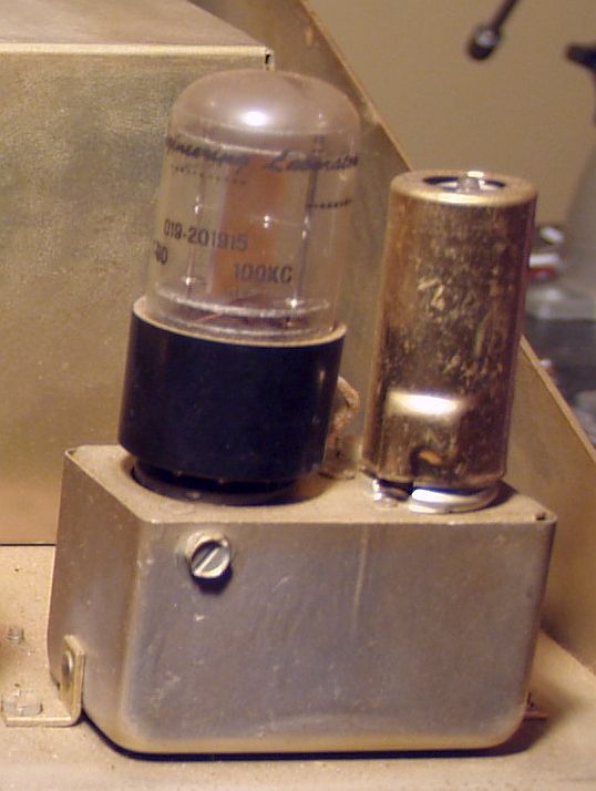
The 100-kHz crystal calibrator is shown below. The 6AU6 oscillator vacuum tube is inside a shield on the right-hand side of the picture. The 100-kHz crystal is on the left-hand side of the picture. The quartz crystal element is inside a glass envelope and plugs into the calibrator similar to a vacuum tube.
The underside of the chassis was mostly clean, but there were a few remnants of spider webs. The underside of the chassis is shown below.
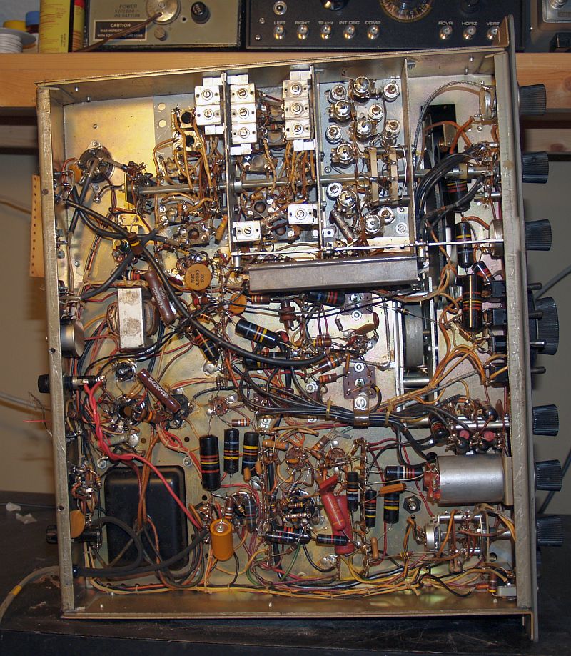
Note that there are numerous "black beauty" capacitors throughout. I counted at least 22 of them.
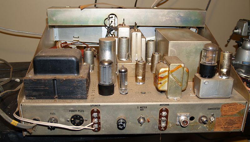
The top of the chassis did have some dirt . I cleaned it off with a toothbrush, water, and Comet cleanser. The top of the chassis before cleaning is shown below.
The radio did not work properly when received. In addition to repairing the notch filter, I had the replace the 12BY6 first converter oscillator tube as it was weak. The radio does work faily well now, but there is a "motorboating" effect present. You can hear it on SSB as someone is talking and it is really noticeable when zero beating a CW signal withe the BFO on. I attempted to isolate this problem, but without success. I suspect it may be associated with the "black beauty" capacitors used as bypass capacitors, but I could not determine which one might be the culprit, short of replacing them all.
A previous owner has made a modification to this radio. The filament of the 12BY6 first converter oscillator is always on and a chassis heater is always on when the radio is plugged into the wall. Hallicrafters did this such that the radio would always be stabilized and ready to use the instant the radio is "turned on." Originally, there was an internal pigtail fuse for the oscillator filament, but a previous owner added a fuse holder to the rear chassis and removed the pigtail fuse.
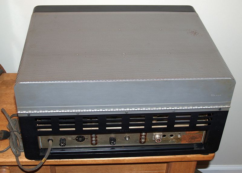
Below is a picture of the back of the radio.
Regulator |
Mixer |
Oscillator |
kHz IF |
Detector |
Audio Amp |
AM Det |
Amp |
Output |
Calibr. |
|||||
The radio even had a "caution" tag inside and its string that instructed the original purchaser to untighten or remove a screw that secured the tuner during shipment.