It receives both AM voice and CW (code) broadcasts with a built-in fixed-frequency beat frequency oscillator (BFO). A switch on the front panel turns on the BFO. The BFO control also acts as a sensitvity control making reception of extremely weak signals possible.
It is designed to operate from 105 to 125 50/60-cycle (Hz) AC current or 210 to 250 VAC or VDC using a special line cord adapter. The radio is an ac/dc set as it does not have a power transformer. The radio has a selenium rectifier. Power consumption is 30 Watts.
An round permanent Alnico V magnet speaker is mounted on the right side of the chassis. A 1/4-inch phone jack is provided on the front panel for plugging in a pair of headphones with impedance from 50 to 10,000 ohms. Insertion of the headphone plug automatically disconnects the internal speaker. A Receive/Standby slide switch on the front panel permits silencing the receiver without turning off the receiver. The volume control turns the radio on and adjusts the volume.
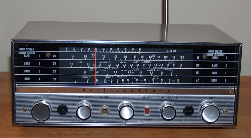
The radio has a main tuning slide-rule dial and a bandspread side rule dial. The Band 1 dial scale is the standard broadcast band. The standard broadcast band is marked with the old "CD" (Civil Defense) emblem and a dot at 640 and 1240 kilocycles to indicate the former two official civil defense frequencies. In a civil defense emergency, one would tune to either of these two frequencies for official civil defense news, instructions, and information.
The shortwave bands are marked Band 2, 3, and 4.
The bandspread is at the top of the dial calibrated from 0 to 100. One sets the bandspread to 100 to make the main dial calibrated. Turning the bandspread tunes the radio down in frequency.
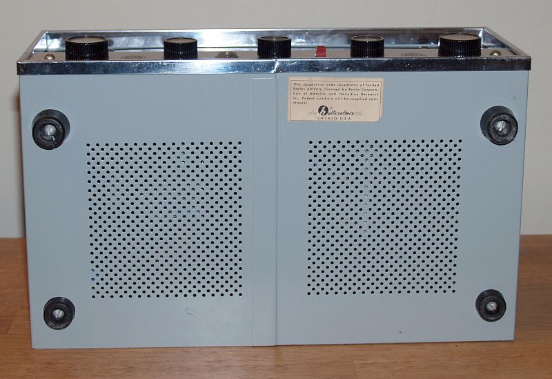
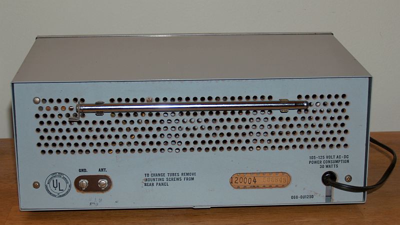
The radio has a built-in ferrite antenna for AM broadcast and a 45-inch collapsible whip antenna for shortwave reception. The whip antenna is often missing and must be attached to the external antenna terminals when used. Provisions are included on the back panel for storing the antenna when not in use.
The radio was manufactured between 1961 and 1964.
When I received this radio, it did work with some audio hum and it was in good cosmetic condition. A previous owner had changed the selenium rectifier to a silicon diode and changed one of the power supply capacitors but left the original capacitor connected. I replaced the other two capacitors and the emitter bypass capacitor of the audio output stage. I disconnected the wires to the original multi-section capacitor, but left the original capacitor in the radio to preserve the original look. I realigned the oscillator and RF stages. The radio works well.
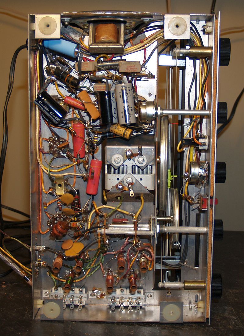
Below is a picture of the bottom of the chassis. The two black and one blue capacitors are the three I replaced. The gray capacitor is the one installed by a previous owner.
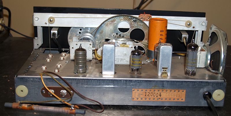
Below is a picture of the top of the chassis.
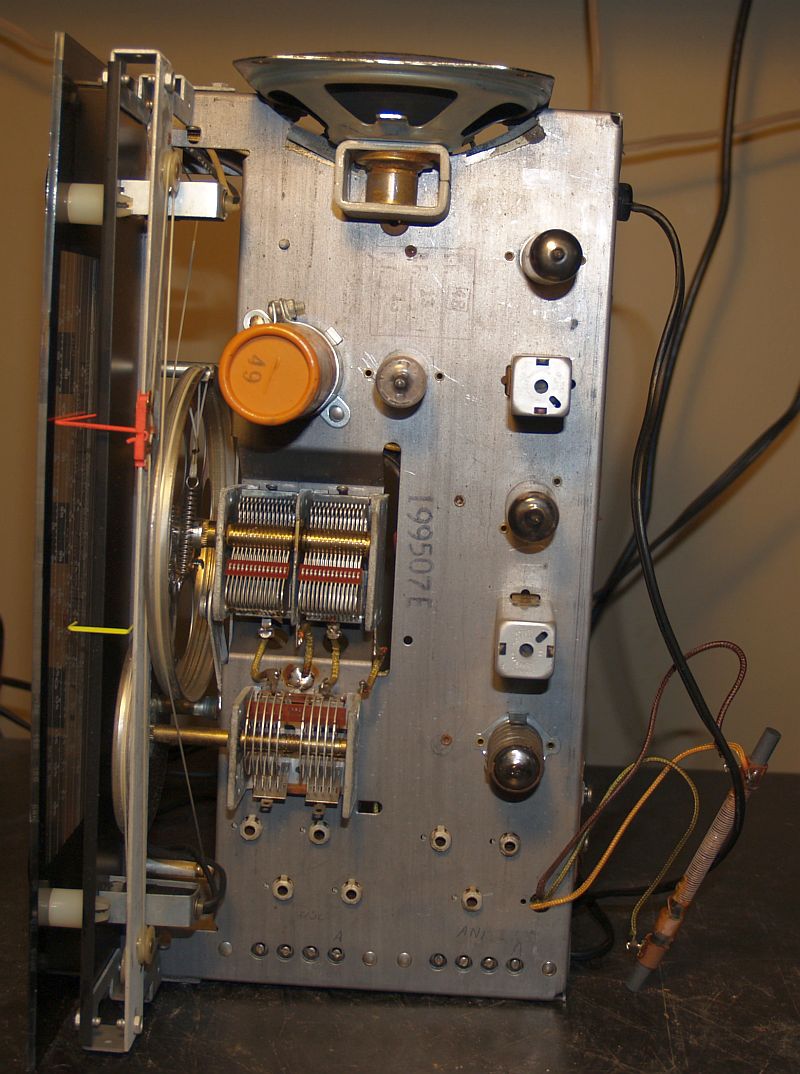
Below is another picture of the top of the chassis from the rear.
Below is a picture of the rear of the radio with the whip antenna installed on the antenna terminals.
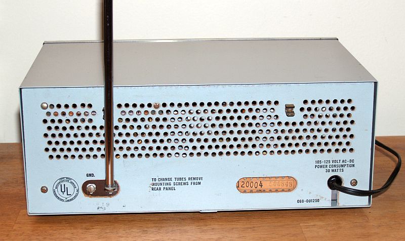
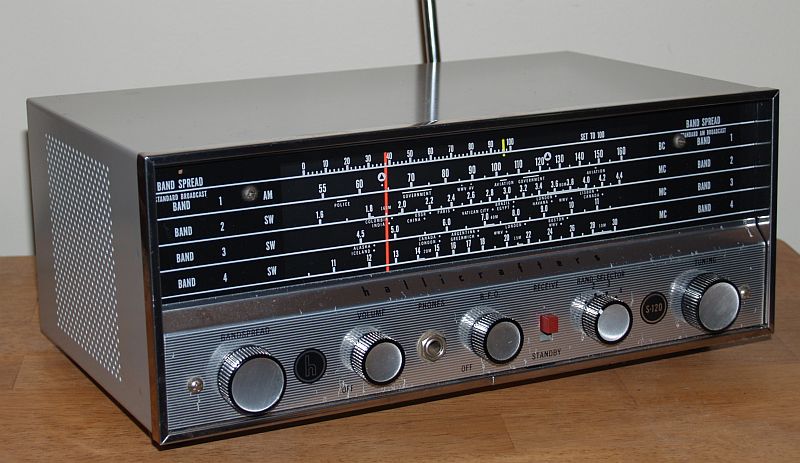
Below is a picture of the radio with the whip antenna in its stowed position.
Below is a picture of the bottom of the radio.