When I received this radio, it was extremely dirty and did not work. It would power up, but the radio had an intermittant popping sound and sometimes a lot of static - even when I brought it up slowly with a variable transformer (Variac). I noticed the radio had been serviced before as there was newer solder joints throughtout. The multi-section power supply filter capacitor was not attached to the chassis - it was just hanging. But the most serious problem I noted was an open winding on the antenna coil. That issue suggested one of the 4 frequency bands may not work. Another issue I noted was the bandspread dial cord had come off the pulley, but the cord and spring were in tact. The bandspread rotor plates were bent such that they shorted to the stator plates when it was moved to the extreme end of its rotation. I also noted the dial light was missing.
After investigating further, I noted a 22-ohm resistor (R18) in the power supply circuit was missing. Also the 15-ohm resistor (R17) in series with the dial lamp was also missing. The missing 15-ohm resistor is why the dial lamp did now work when I replaced the lamp.
Considering all of the problems I found upon inspection, this radio was certainly one of the more difficult radios I have had to work on - it is one of the most challenging to fix. I may have given up except the metal cabinet was in such good shape and the radio had all of the original knobs and the speaker was good.
I replaced several capacitors (one was shorted), I replaced the resistor in the power supply, and I replaced the power supply capacitors (even though the multi-section capacitor appeared to be still good). I also relocated the power cord to attach to a terminal strip I mounted instead of to the rectifier tube socket and I added a strain relief to the cord to prevent it from pulling out of the radio. All of this did not stop the popping and static although it seemed to slow it down.
The popping semed to be associated with the Automatic Volume Control (AVC) circuit. It would occasionally act up by placing positive grid voltage on the control grids of the RF amp/oscillator/mixer (12SA7) and the IF amp/BFO (12SG7). The positive grid voltage would essentially shut off the amplifiers thus producing no audio output. I replaced these two tubes and the detector/audio amp (12SG7) but it did not work for long. I did not have a 12SG7 so I replaced it with a 12SK7. The original 12SG7 in the radio was a Hallicrafters tube - probablly original to the radio.
I replaced most of the original capacitors in the radio, but the intermittant popping and static was still present. I even replaced several of the resistors in the AVC circuit, but the popping problem still persisted and there was still about 1 Volt positive on the two diodes in the 12SQ7. Eventially, I completely disconnected the detector tube & audio amp tube (12SQ7) and the AVC circiut from the second IF transformer. I noticed there was about 70V on the wire that would connect to the diodes! That situation sugested a short circuit within the 2nd IF transformer - the 70V I measured was the plate voltage for the 12SG7 connected to the primary of the 2nd IF transformer. There must be a high-impedance short in the transformer becasue I could not measure a short with my Fluke 87 DVM.
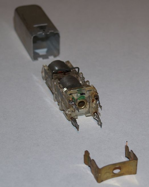
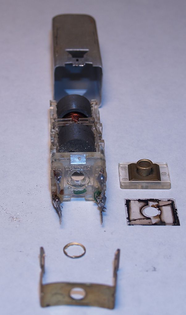
So I removed the 2nd IF transformer from the chassis and took it apart to investigate. The picture below shows the transformer removed from the chassis and its metal cover removed. The brass U-shaped piece in the foreground holds the transformer to the chassis.
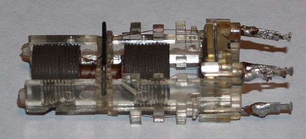
The picture below shows the transformer assembly with its metal case removed. The transformer comprises two coils wound on a common paper bobbin each surounded by a ferite core. A silver mica capacitor is incorporated into the plastic supporting structure adjacent to the 4 pins. The capacitor can be seen just to the left of the pins on the right. A thin silver-plated mica sheet is sandwiched between the plastic base on the right and a cover on the left.
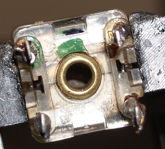
A brass eyelet holds the plastic cover in place. The picture below shows the bottom of the transformer. The eyelet can be seen in the center of the transformer base.
I used a Dremel tool with a sharp pointed tip to mill away the ring of the eyelet. It did not take long for the ring to separate from the eyelet. Once the ring separated, I could remove the cover from the silver mica capacitor.
The picture below is a view of the transformer showing the silver mica capacitor at the base of the transformer with the plastic cover removed. The silver-plated mica sheet is the light-colored material with black portions and streaks. The mica sheet is sandwiched between metal fingers that are part of the 4 pins on the base of the transformer.
Using a tweezer, I removed the silver plated mica sheet held in place by the metal fingers. The mica sheet is shown below.
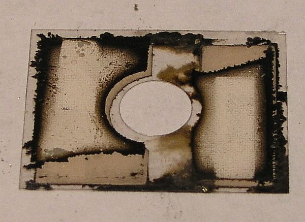
The mica sheet actually comprises two separate capacitors with a common mica dielectric. There are four separate silver pads - two on the top, and two on the bottom. Two of these pads (one on the top and one on the bottom form a single capacitor. Electrically, one capacitor is in parallel with the primary winding of the transformer, and the other capacitor is in parallel with the secondary winding. The two capacitors are not electrically connected together but as stated earlier, they share the same dielectric.
Notice all of the black portions. The black is where the silver had migrated through the mica. Unfortunately, the silver had migrated across the mica and created a high-resistance short circuit between the silver pads on the top and between two pads on the bottom. This situation shorted the primary of the transformer to the secondary and was the reason I could measure the plate voltage on the secondary of the transformer as stated above.
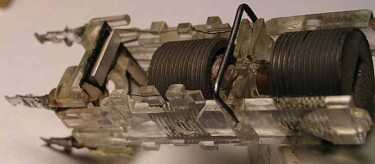
The picture below shows the completely disassembled transformer. In the picture you can see the transformer metal cover, the brass clip that holds the transformer to the chassis, the transformer assembly, the plastic cover for the silver mica capacitor with the eyelet through it, the silver-plated mica sheet, and the eyelet ring that I milled off.
The silver mica capacitor cannot be repaired. I replaced the mica capacitors by soldering silver mica capacitors to the pins under the chassis after the transformer is reinstalled in the radio. But before reinstalling the transformer, I have to put it back together.
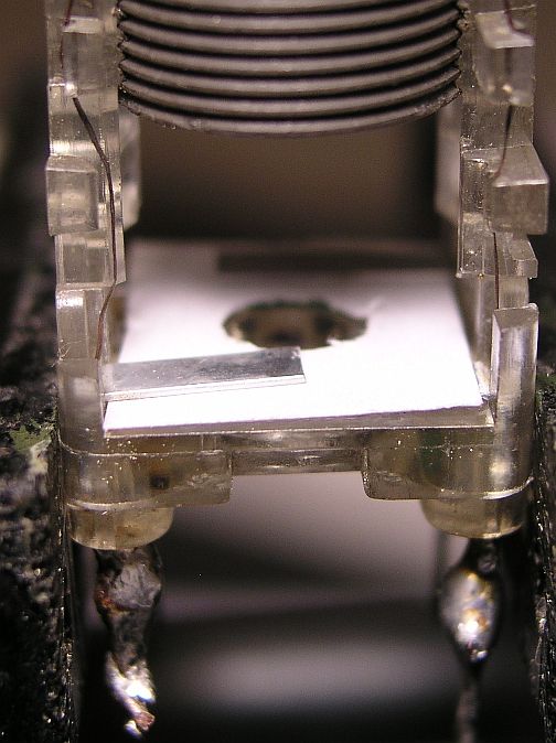
To keep the metal fingers from shorting without the mica sheet in place, I slipped a sheet of paper between the metal fingers. The picture below shows the paper inserted between the metal fingers.
I reinstalled the plastic cover over the fingers and paper and glued it in place using Gorilla Glue. Gluing the cover in place prevents the metal pins from pushing back into the transformer when I resoldered the connections inside the radio.
Now I had to figure out what capacitance values to substitute for the silver mica capacitors. I did this sort of by trial and error. I figured the capacitance should be somewhere between 50 and 150 pf so that is where I started. I placed the transformer in an Panavise and used a signal generator and oscilloscope and tried several values of capacitors until I got the transformer to resonate. I connected the output of the generator to the transformer through a 1M ohm resistor to prevent loading of the circuit. Once I selected the capacitors to get the resonance frequency close to 455 kHz, I tuned the ferite cores to precisely get the resonance at 455 kHz, the IF of the radio. I had to retune it when I put the metal cover back on the transformer. With the cover on, the resonance frequency shifted about 30 kHz higher. The replacement silver mica capacitors that made the 2nd IF transformer resonate at 455 kHz were 100 pf on the primary and 150 pf on the secondary.
Below is a picture showing the bottom of the chassis with the 2nd IF transformer installed with the replacement silver mica capacitors.
I reinstalled the 2nd IF transformer in the radio and the radio worked for a while. The popping and static were gone, but there was still positive voltage on the AVC line. After some thought, I suspected the 1st IF transformer was also shorted internally because of the silver migration through the mica in that transformer. I disassembled and repaired that transformer as described above. The 1st IF transformer mica sheet exhibited silver migration similar the the 2nd IF transformer. The replacement silver mica capacitors that resonated the 1st IF transformer at 455 kHz were 100 pf on the primary and 68 pf on the secondary.
Below is a picture showing the bottom of the chassis with the 1st IF transformer installed with the replacement silver mica capacitors.
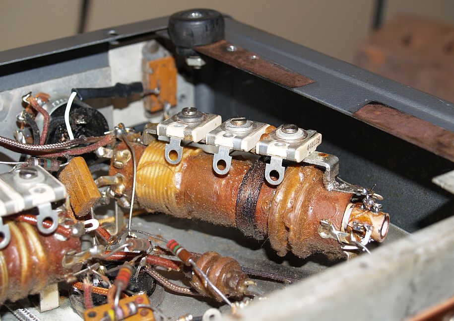
Repairing the open antenna coil took a little more thought. The open coil was the primary winding of the AM broadcast band antenna transformer. The radio would work with the open coil, but only the upper 1/2 of the band would work. Fortunately, the primary coil is easily accessed in the circuit and made my repair easier. I had a generic AM oscillator coil that can be used to replace defective oscillator coils in many broadcast radios. This replacement coil is small and would fit inside the Hallicrafters antenna coil. So I connected the replacement oscillator coil primary winding in parallel with the open original coil and placed the replacement coil inside the Hallicraters coil so it would magnetic-couple the antenna signal into the secondary winding as the original Hallicrafters coil would do. After installing the coil inside, I had to slightly back it out of the original coil to reduce the coupling because with it pushed in too far, it over-coupled the antenna signal thus causing heterodyning on many stations. I suspect this overcoupling created image rejection problems thus causing the hetrodynes. This fix works quite well and the radio works well on AM broadcast now. The picture below shows this coil repair. The replacement oscillator coil that I inserted can be seen in the right-hand end of the original antenna coil. The open winding is the darker-colored winding under and slightly to the left of the right-most tuning capacitor on top of the coil assembly.
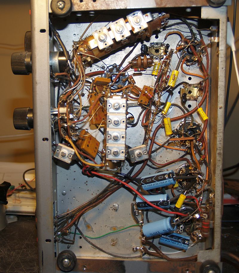
Below is a picture of the bottom of the radio chassis after I replaced the numerous parts.
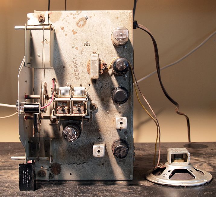
Below is a picture of the top of the radio chassis.
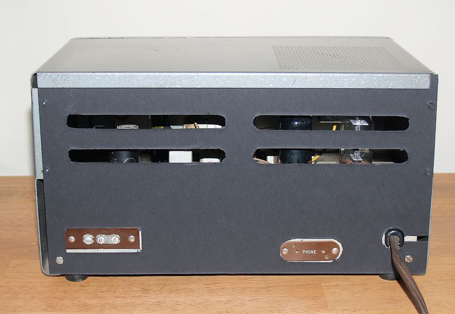
Below is a picture of the rear of the radio. The original back cover is missing but I made a back for it.
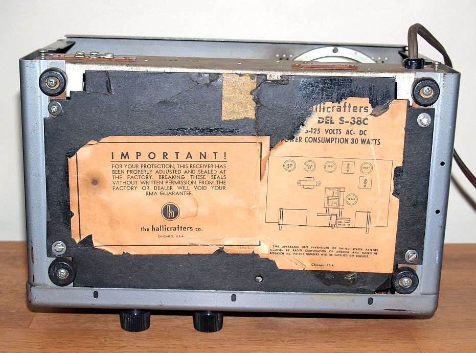
Below is a picture of the bottom with the pasteboard bottom cover in place.
After all of this work, this radio works well now on all of the four frequency bands. I realigned all of the bands to bring the dial into alignment.
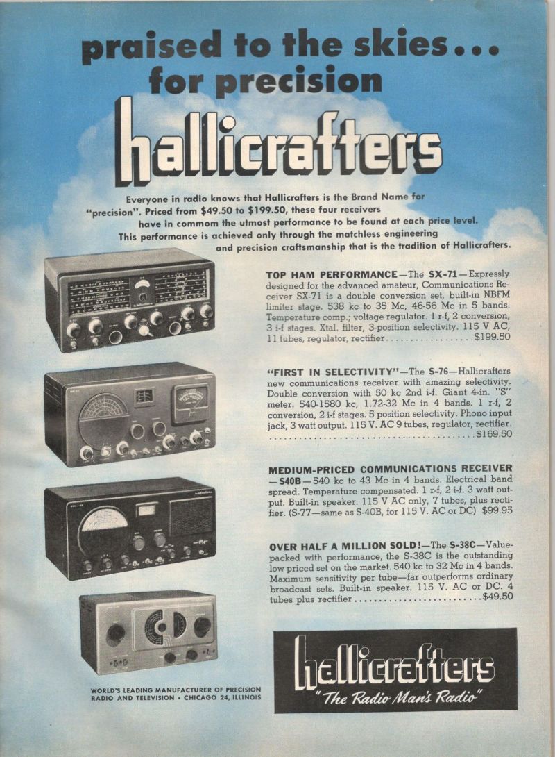
Below is a picture of a Hallicrafters advertisement from the July 1952 Radio & Television News magazine describing the radio. Note that the radio sold for $49.50 in 1952.