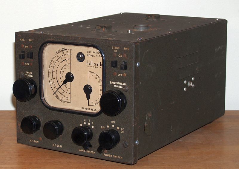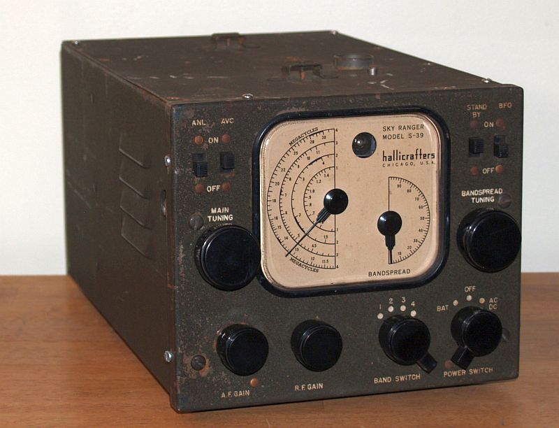
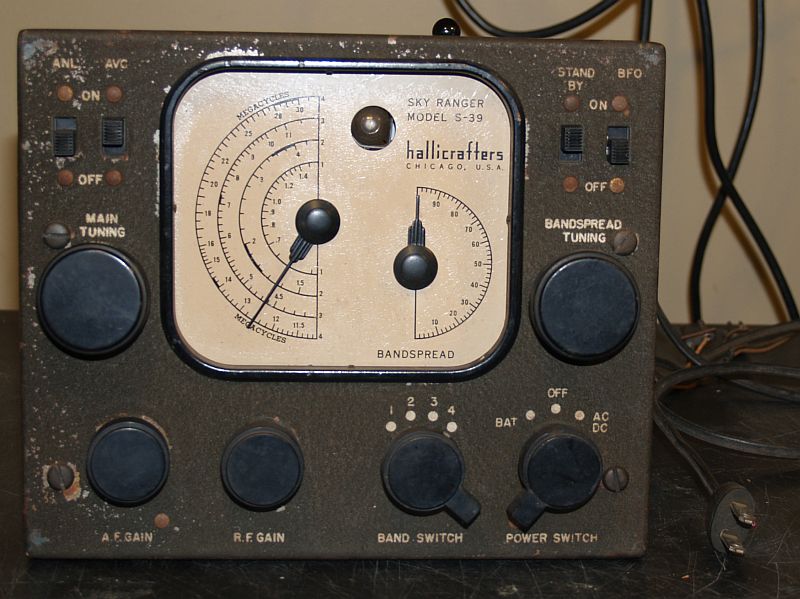
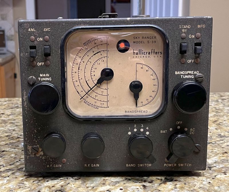
This is a Hallicrafters Model S-39 Sky Ranger Portable General Coverage Receiver manufactured in 1942. This radio is a 9-tube portable radio with four bands covering 0.550MHz TO 30MHz. The intermediate frequency (1F) is 455KHz. The radio has a beat frequency oscillator (BFO) for continuous wave (CW) reception, a bandspread dial, automatic noise limiter (ANL), a telescoping antenna and jack for an external antenna, a built-in speaker and headphone jack, and one stage of RF amplification.
Controls on the front panel include:
Main Tuning
Bandspread
AF Gain
RF Gain
Band Switch
Battery/OFF/AC/DC Switch
ANL ON/OFF
AVC ON/OFF
Standby ON/OFF
BFO ON/OFF
The power source is two 45-Volt batteries for B+ Voltage and a 6-Volt battery for the tube filaments. The radio can also be powered by 120 Volts ac or dc. There is no isolation transformer and as such, the internal chassis is connected to one side of the power line. The front panel and external enclosure is electrically isolated from the internal chassis.
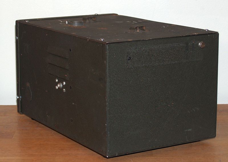
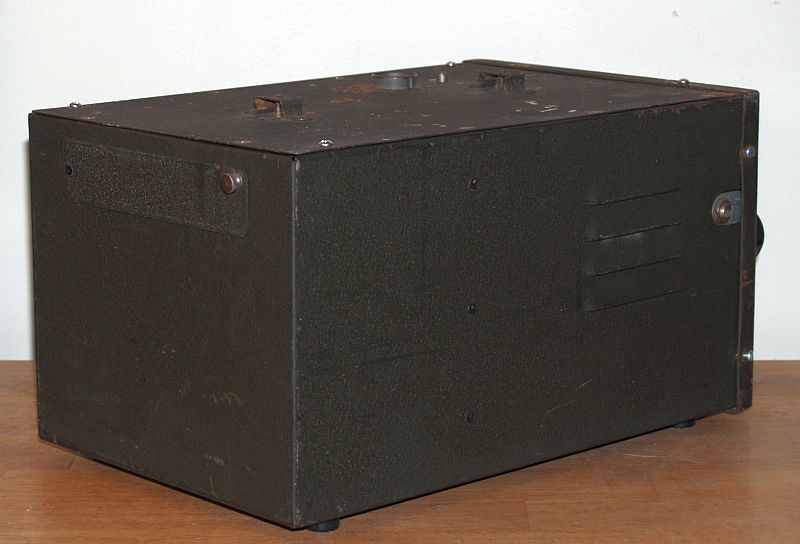
This radio is similar to the Hallicrafters S-29 radio and was used by the US military for troop entertainment and a morale booster. The military version of this radio is R-80. The radio is housed in a metal cabinet painted dark olive green. The top cover has a carrying handle and has access to the telescoping antenna. The handle and cover for the antenna access was missing on this radio when I received it. Batteries and tubes are accessed by removing the top cover that is held in place with screws. The connector for the externa antenna is accessed by moving a small cover on the left-hand side of the radio. The headphone connector is on the right-hand side of the radio near the internal speaker. When I received the radio, the top cover was held in place with only a couple of screws. The front panel had no screws to secure it to the metal cabinet. In addition, the plastic dial cover was missing, and the main dial cord was broken, but the dial cord spring was still present. Otherwise, the radio, including the dial markings, was in reasonably good shape. The paint on the cabinet is scratched in several places.
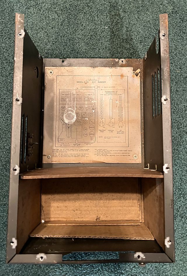
Below is a picture of the inside of the cabinet with the chassis removed. The batteries are placed in the compartment in the rear that is lined wih corregated cardboard.
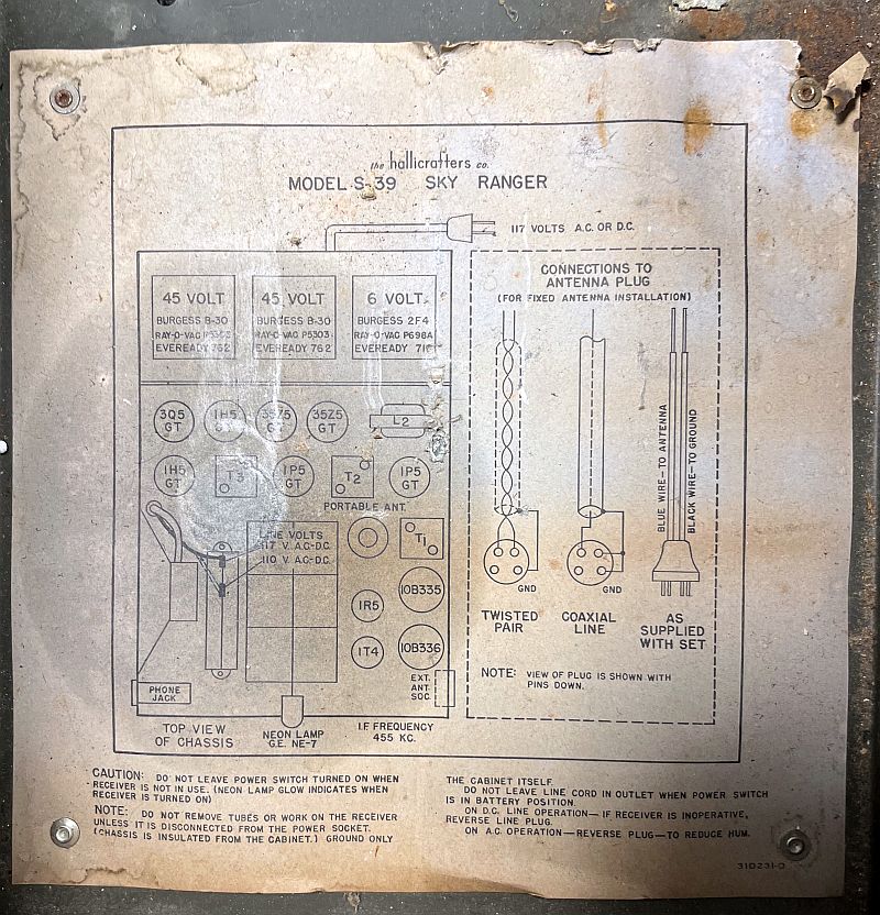
Below is a picture of the tag inside on the bottom of the cabinet. The tag shows the battery layout, the vacuum tube layout, connections for use with 117 or 110 VAC line voltage, and connections to the antenna plug on the side of the cabinet. The 117/110 VAC connections are associated with two different taps on a power resistor.
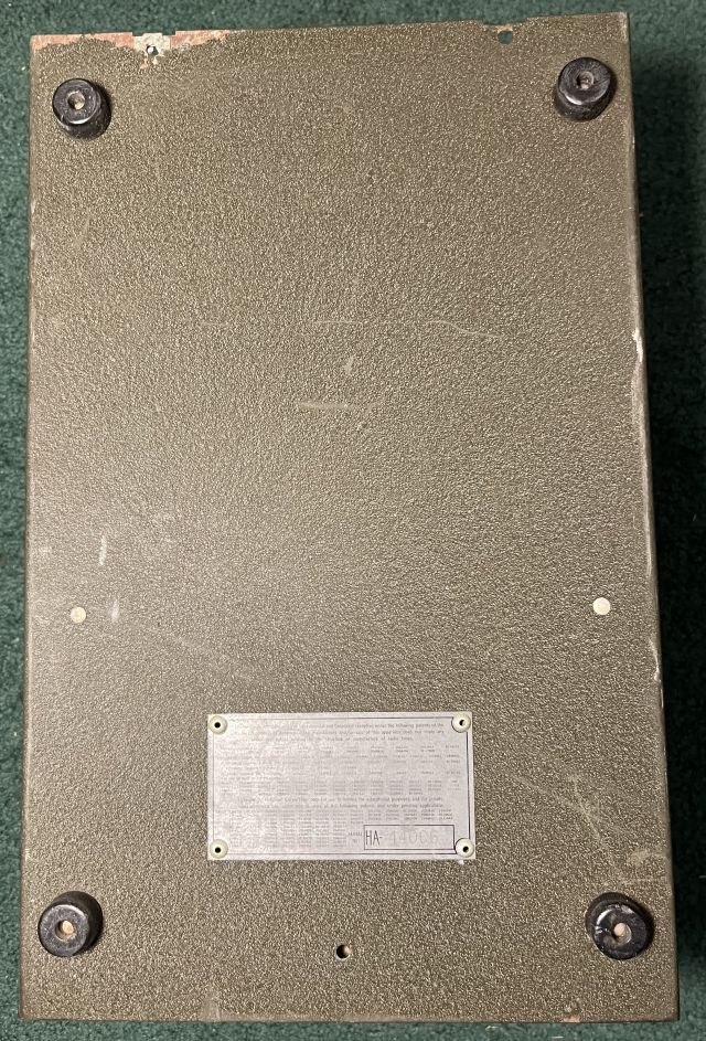
Below is a picture of the bottom of the cabinet.
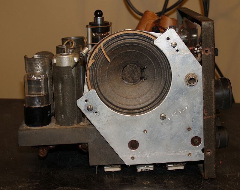
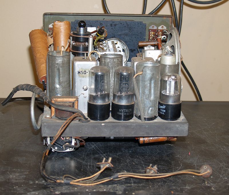
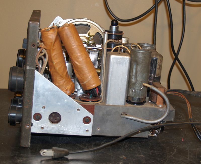
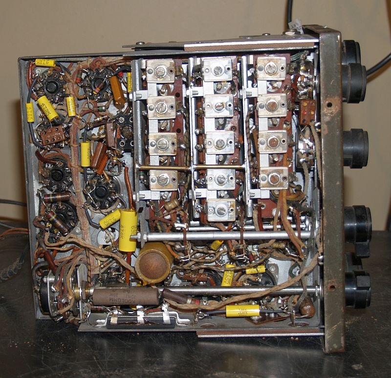
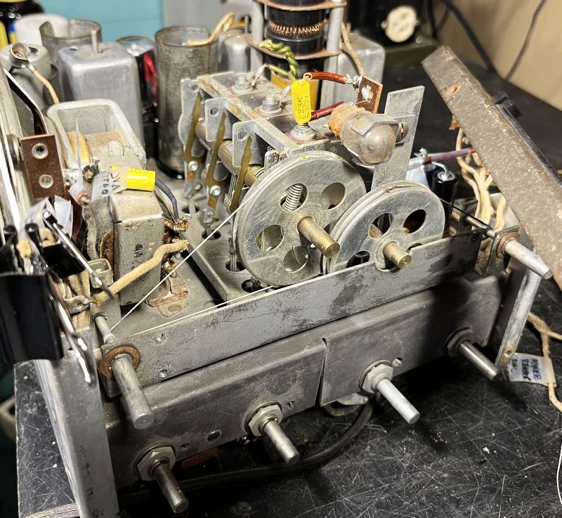
Below are pictures of the original radio chassis removed from the cabinet.
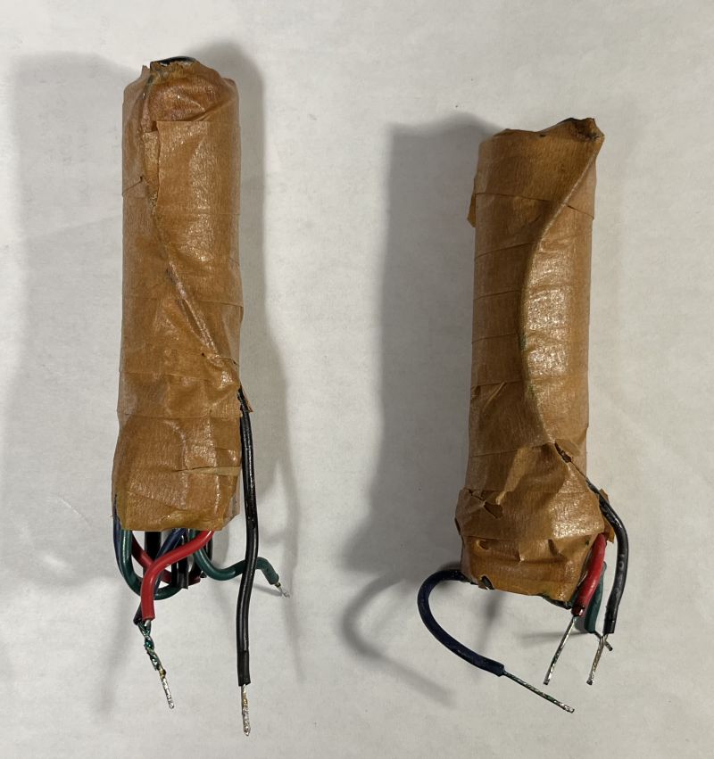
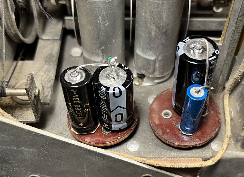
Upon close inspection of the radio, the most noticable repair/modification is the two filter power supply capacitor assemblies. The capacitor assemblies plug into a 4-pin tube socket and into a 6-pin tube socket. These capacitor assemblies had been replace with larger multi-section capacitors connected to the plug assemblies of the original capacitor assemblies as shown in the picture below.
I replaced the above with smaller newer capacitors using the plug assemblies of the original capacitor assemblies as shown below.
Another modification is an external connection that had been added to the plate of the 1R5 mixer/converter tube. This modification is the gray shielded cable seen at the top of the picture below showing the original bottom of the chassis.
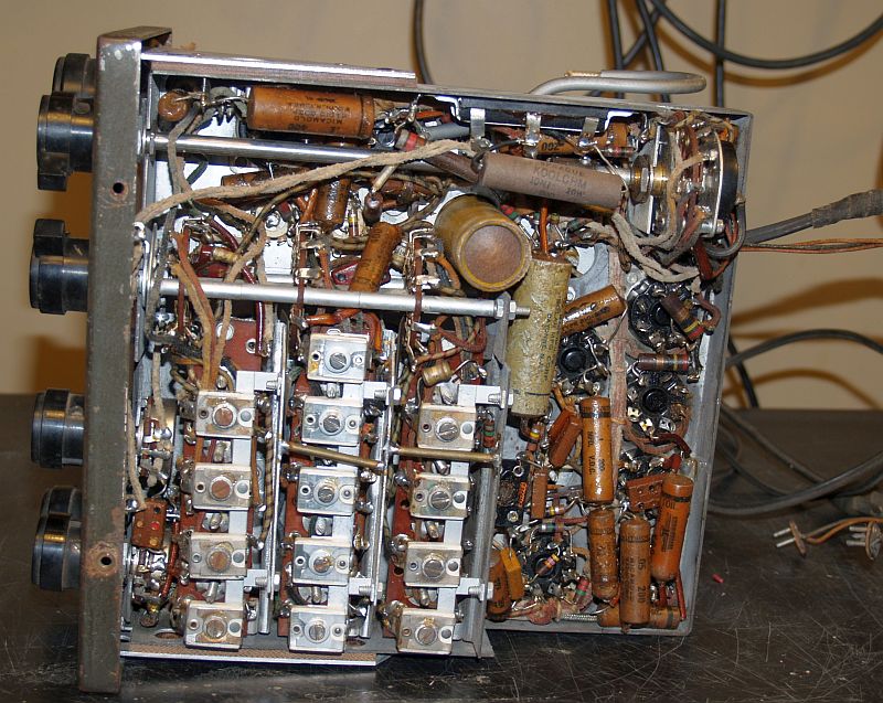
The connection is terminated to an RCA phono jack added to the metal enclosure. I presume the intended use of this modification is to provide a signal for an external panadpater. I removed the connection but left the external phono jack in place.
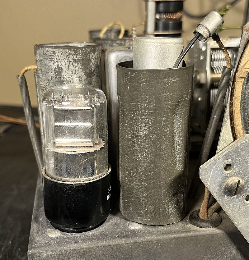
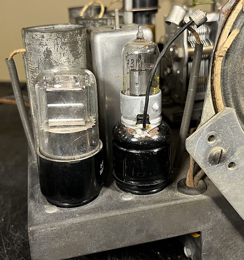
Another modification is a 1S5 vacuum tube substitution for the 1H5 vacuum tube used for the BFO. The 1S5 vacuum tube is a miniature diode/triode tube; however, the 1H5 diode/triode tube is an octal tube. As such, an adapter with a wire for the grid cap has to be used in order to use the 1S5 in place of the 1H5 vacuum tube. I replaced this modification with a 1H5 vacuum tube, but the BFO did not oscillate. Therefore, I maintained the 1S5 modification and the BFO works as expected. The picture below shows this modification.
The picture below shows the 1S5-to-1H5 adapter.
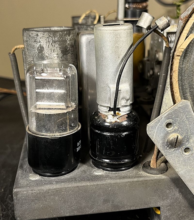
The picture below shows the 1S5 vacuum tube installed in the adapter with the shield removed.
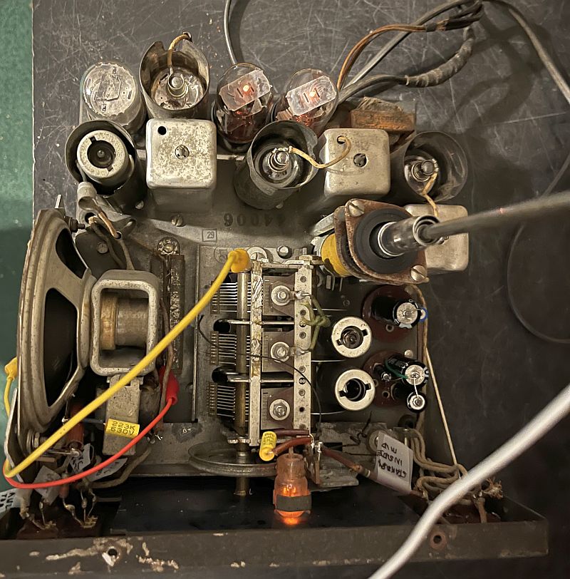
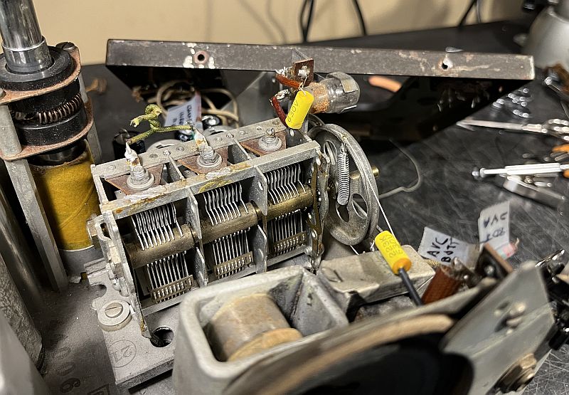
I replaced all of the wax paper capacitors in the radio. The radio is quite compact, and access to the capacitor leads was sometimes challenging. I had to loosen the shaft at the coupler attached to the power switch and move it forward out of the way to access several capacitors. The picture below shows the chassis with the new capacitors.
The neon indicator lamp worked after replacing the capacitor associated with the RC oscillator circuit that powers the neon lamp. The illuminated lamp is shown below.
All of the vacuum tubes, except for the 1S5 BFO vacuum tube and the 1H5 detector AF amplifier vacuum tube, in the radio tested weak. The 1R5 mixer/converter vacuum tube produced no local oscillator signal. The two 1P5 vacuum tube IF amplifiers tested very weak. I replaced the 1T4 RF amplifier, the 1R5 mixer/converter, and the two 1P5 IF amplifiers. These replacements also significantly reduced the ac power hum present in the audio.
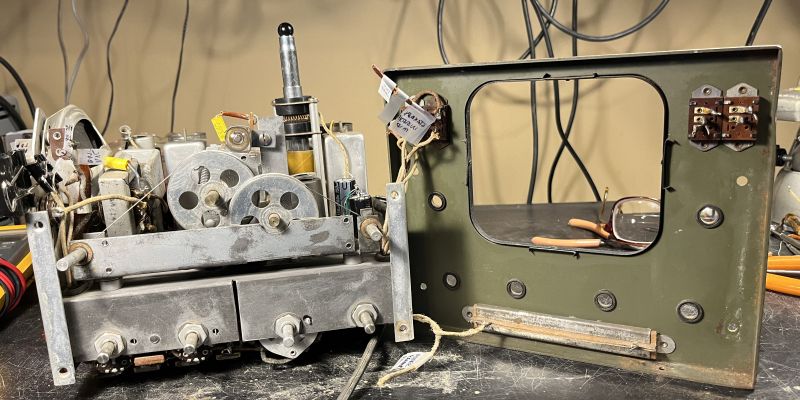
The knobs and front panel must be removed to restring the dial cord and replace the missing plastic lens. The four slide switches are permanently rivited to the front panel. As such, the wires connecting the switches to the panel must be disconnected. I disconnected the wires and resistor to soldered to the ANL and AVC switch and labeled them for reattachemnt. I also disconnected one wire connected to the power resistor mounted on the bottom of the front panel. I also disconnected the 1M-ohm resistor providing power to the indicator lamp. Doing this, allowed the front panel to be swung open to access the tuning capacitor and the back of the front panel as shown below.
Below are pictures of the restrung dial cord. I used the original spring that was still present.
Below is a picture of the radio operating. Notice the orange glow of the neon lamp indicator.
Below are other pictures of the restored radio.