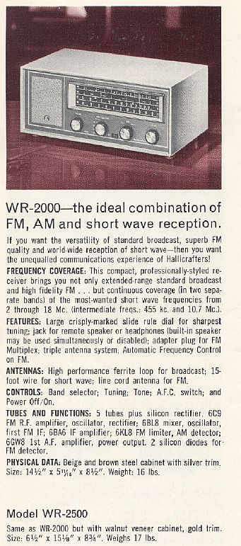
Below is a description from a 1964 Hallicrafters sales pamphlet.
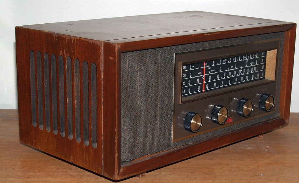
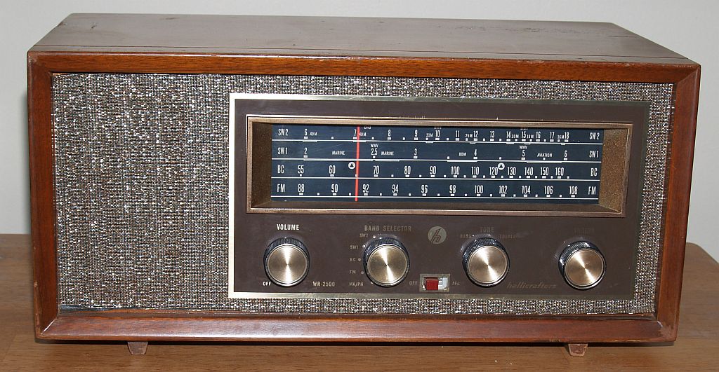
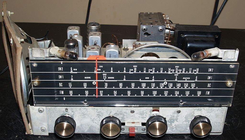
When I received this radio, it was in good shape and did not work. Although some of the lettering in the photograph above appears faded, the lighting is critical to show all of the lettering. The radio would power up, but had hum indicating the power supply filter capacitors needed replacing.
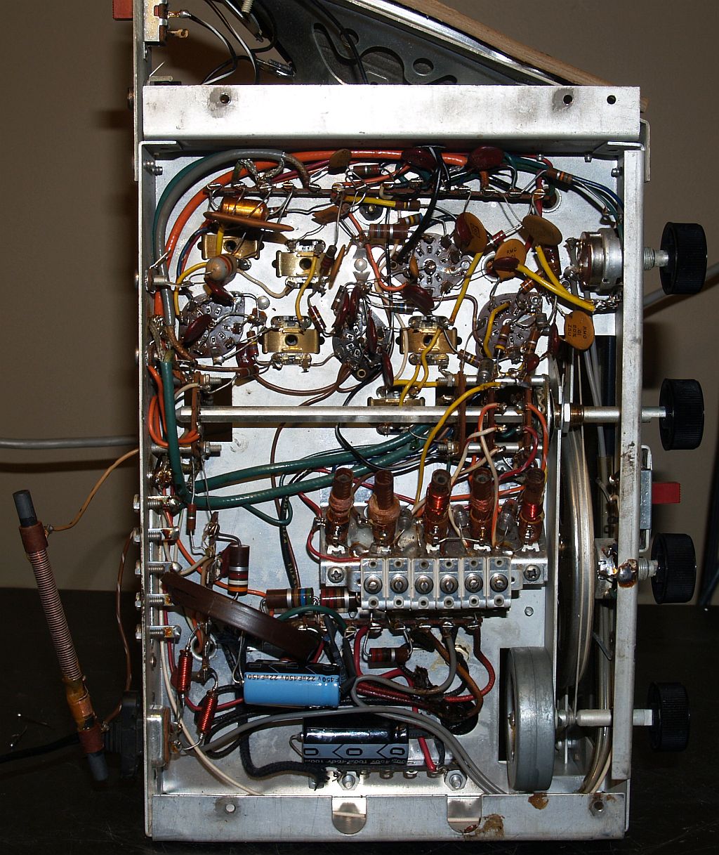
Below is a picture of the chassis showing the multi-section original filter capacitor (brown tubular component at the bottom of the pciture).
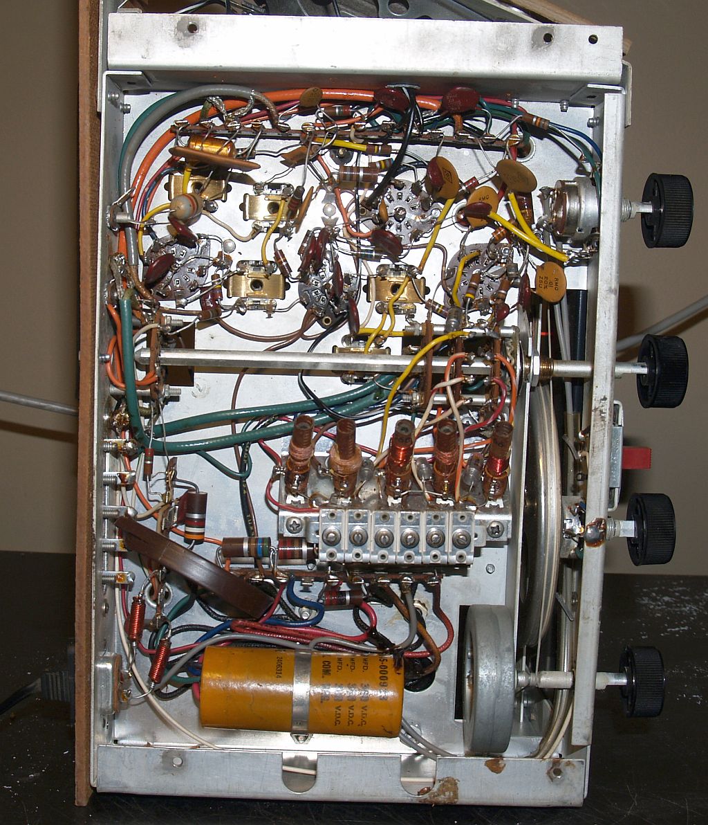
Below is a pictue of the chassis showing the new power supply filter capacitors installed (the blue capacitors at the bottom of the picture).
The AM band and the lower shortwave band worked although the dial was slightly off frequency on both. Minor adjustments corrected those problems.
The FM broadcast band was dead. I opened up the metal enclosure of the FM tuner and I discovered a serious problem. The IF transformer had dislodged from its mount and one wire was disconnected. See the picture below.
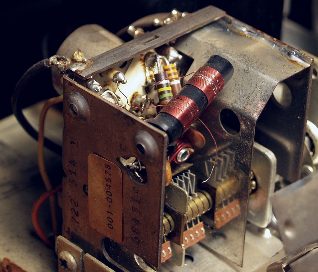
You can see the IF transformer is just "floating" and not mounted to the tuner frame. And you can see the disconnected wire below the transformer. I measured continuity of both coils of the transformer and discovered the secondary winding was open. I carefully inspected it and measured continuity until I found where the winding was broken and carefully soldered a jumper between the two halves of the broken coil. The vacuum tube in the FM tuner is a 6C9 dual tetrode and one of the tetrode plates was connected to the primary of the IF transformer. The other end of the primary was the broken connection and it must connect to the B+, so that is where I connected it. But the tuner did not work (no local oscillator signal); however if I injected a strong signal from my signal generator, the tuner would sort of work (I could receive some FM stations. So I replaced the tube with a new one and the FM band worked but it was significantly off frequency. I retuned the tuner and all of its adjustments and now it works fine.
The lower shortwave band worked but the second (higher band) did not work. After wiggling the oscillator coil for this band and working the bandswitch, the band began to work and is now reliable. I think the bandswitch was dirty.I adjusted the shortwave bands to bring WWV on frequency. I also adjusted the AM broadcast to bring it on frequency. I peaked the 455 kHz and 10.7 MHz IF coils for maximum sensitivity, too. I replaced one dial lamp that was burned out.
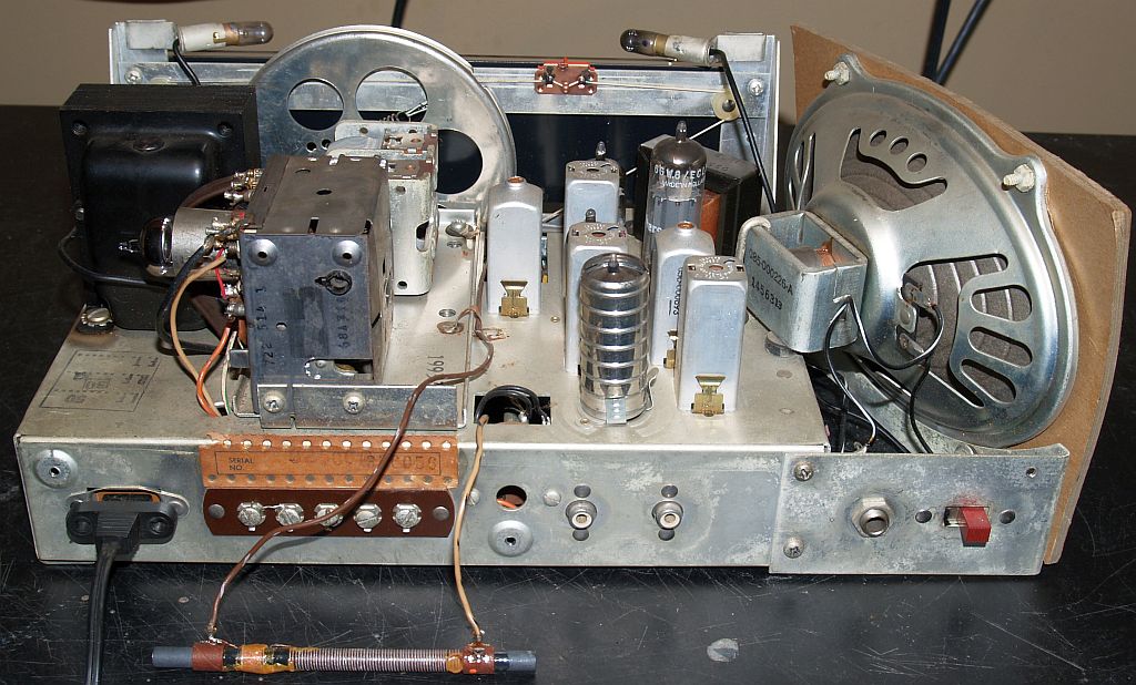
Below is a picture of the top of the chassis.
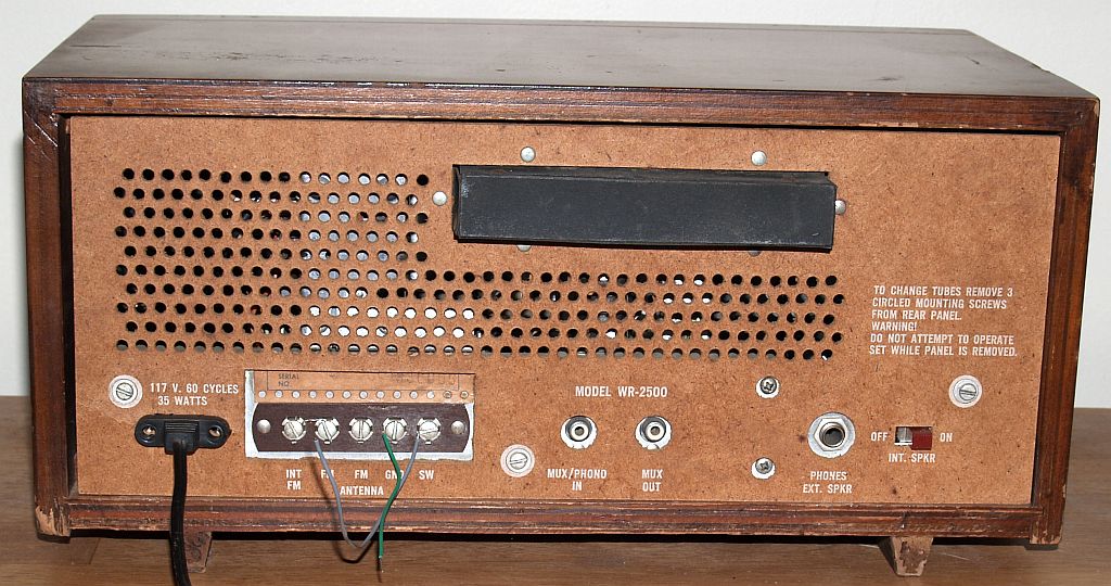
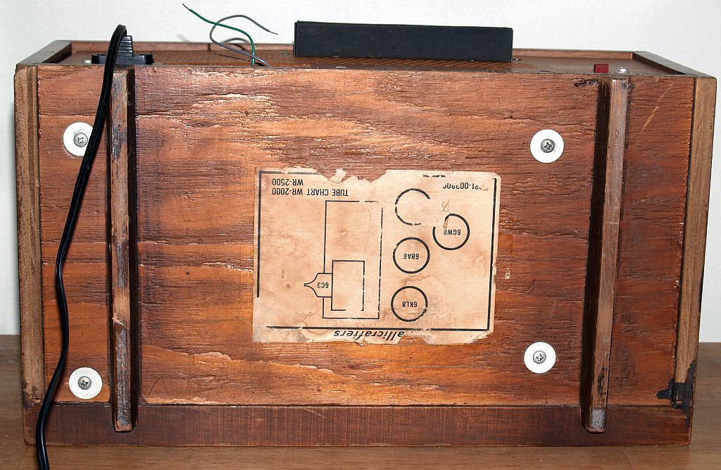
Below is a picture of the top and rear of the chassis.
Below is a picture of the front of the chassis.
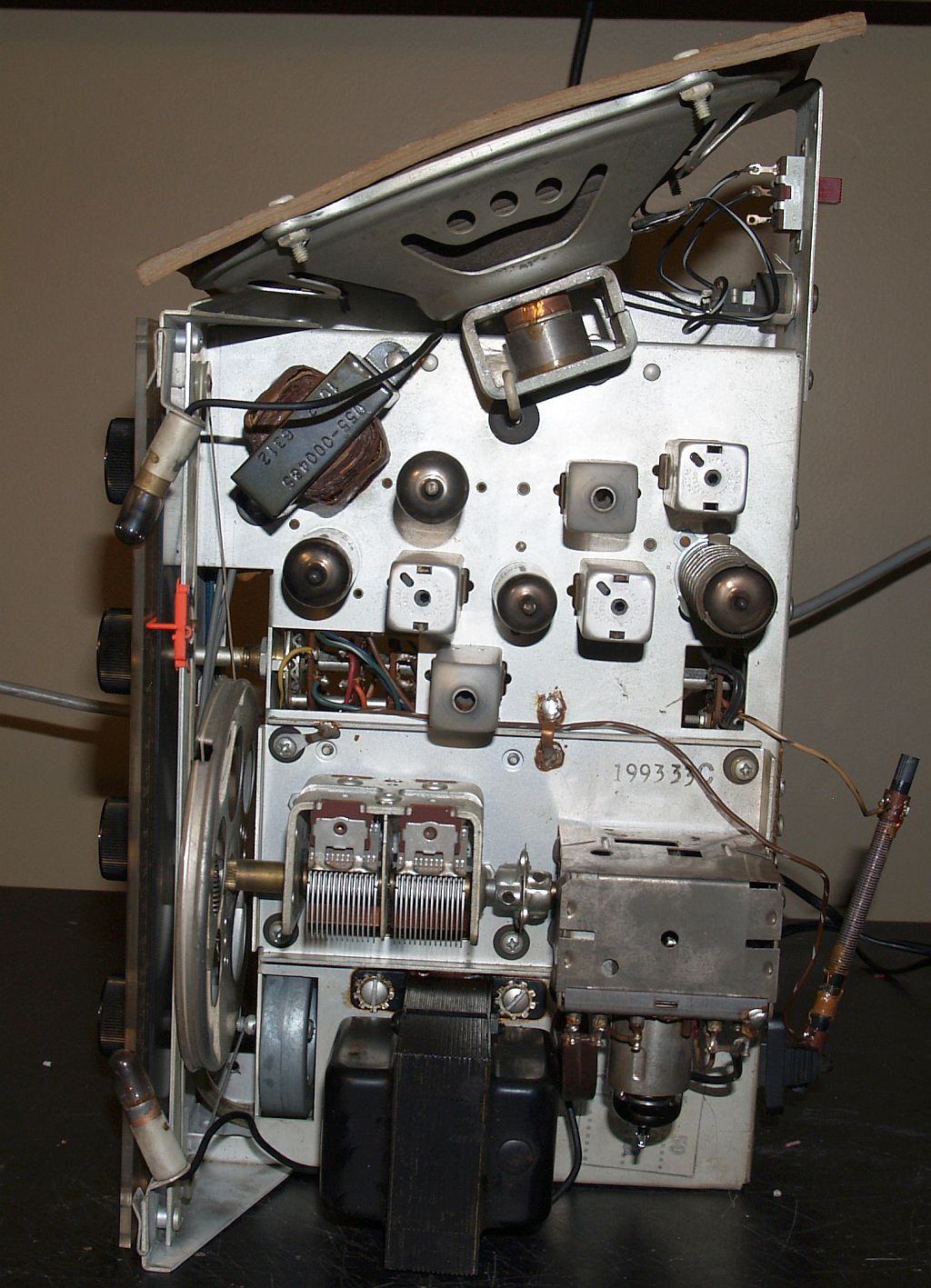
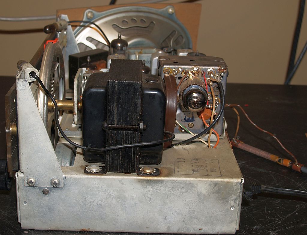
Below is a picture of the left side of the chassis.
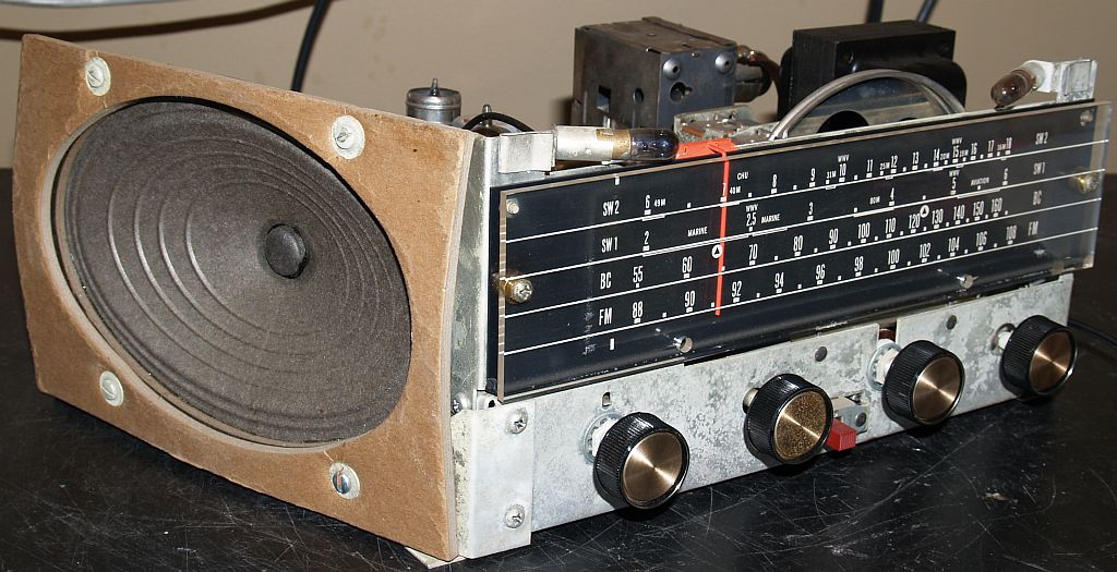
Below is a picture of the right side and front of the radio.
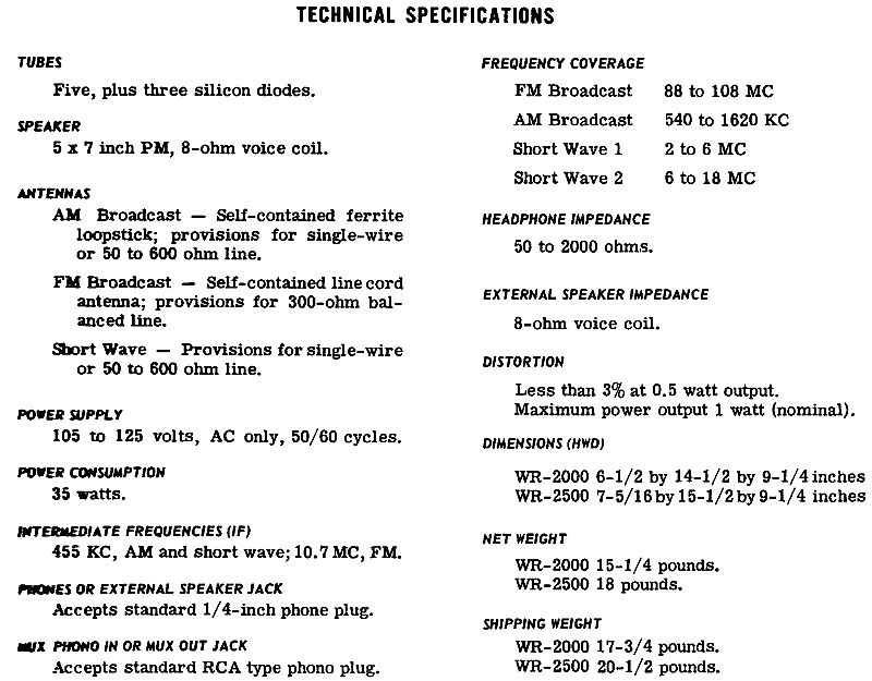
Below are technical specifications for the radio as extraced from the radio service data.