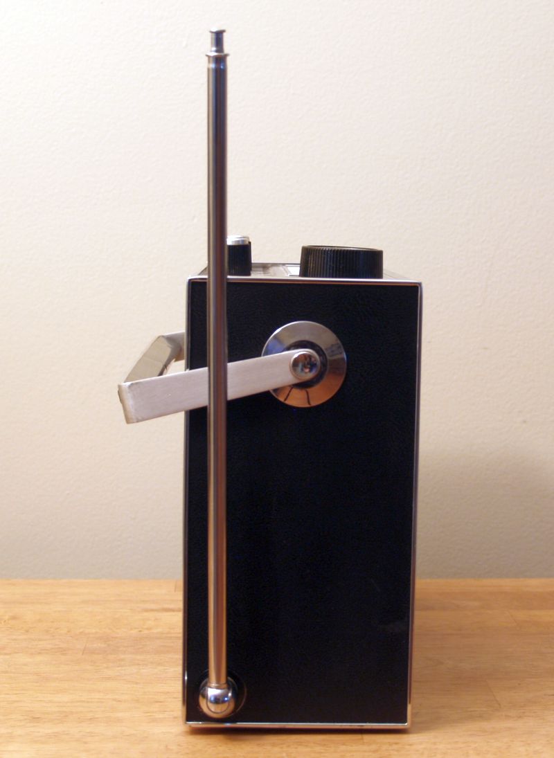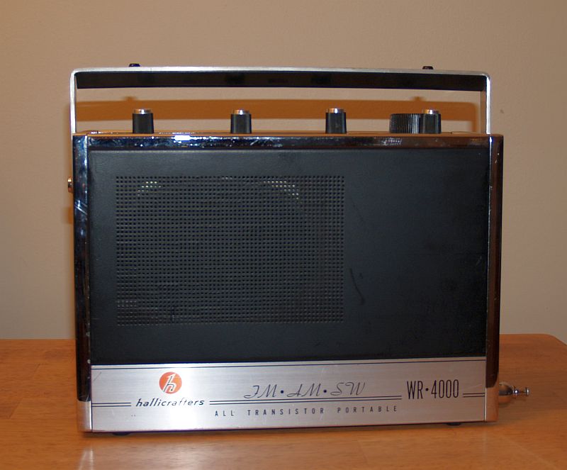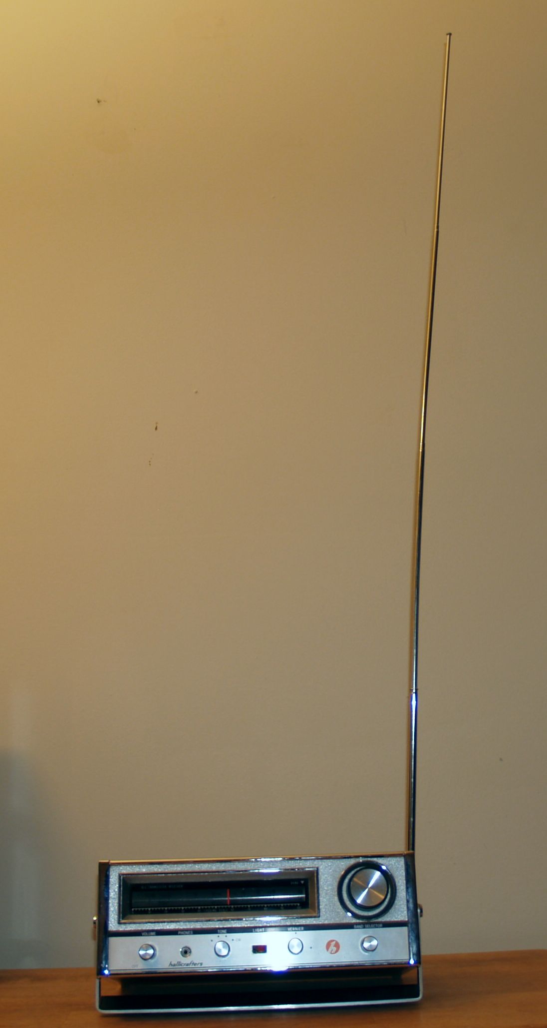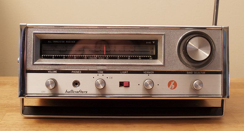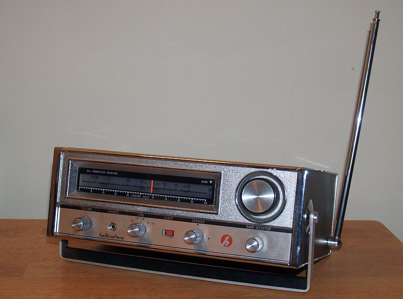
The radio has 14 germanium transistors, 6 diodes,and 2 Zener diode regulators. Long wave and Standard Broadcast AM use a self-contained ferrite rod antenna. Shortwae and Broadcast FM use a telescoping rod antenna on the lower side of the enclosure. Provisions are included for a single wire or 50 to 600 ohm line (wire) antenna. Tuning is facilitated by a rotating drum slide rule dial. The radio has an internal 4 x 6 inch oval speaker.
The radio is powered by 12 VDC comprising 8 1-1/2 Volt D cells. A separate D cell provides power for the two dial lamps. There is no provision for external DC power. However, the 8 D-cell battery pack holder plugs into the chassis using a 2.5 mm ID, 5.5 mm OD, 9.5 mm long coaxial DC power connector. The previous owner cut a hole in the bottom of the chassis for connecting the single wire antenna. External POSITIVE GROUND DC power from a "wall wart" could be connected through the hole and to the chassis in place of the battery pack.
There is a standard miniature-type phone jack on the front panel. Impedance of this connection is 3 to 3k ohms. Audio power output is up to 500 mW undistorted. The controls on the front panel include:
| Main Tuning Knob |
| Audio Frequency Gain control and On/Off |
| 3-position tone and BFO (CW) switch |
| Dial lamp momentary contact switch |
| Fine tuning (for CW operation) |
| Band Switch |
Below is the tuning range of the receiver:
| LW | 180 kHz - 400 kHz |
| BC | 535 - 1650 kHz |
| SW1 | 2 - 4 MHz |
| SW2 | 5.85 - 10.3 MHz |
| SW3 | 11.4 - 18.2 MHz |
| FM | 86.5 - 108 MHz |
When I purchased this radio, it was in good condition but only the FM band worked. Upon investigation into the problem, I discovered the AM/shortwave RF amplifier transistor had been removed and a wire and resistor were left hanging. Apparently, the original RF amplifier transistor had gone bad and someone had the intention of replacing it and never completed the repair. However, the radio was reassembled without replacing the transistor. I installed an NTE 126 germanium PNP and now the AM and shortwave bands work. The three shortwave bands were also significantly out of alignment - realignment of the antenna and RF tank circuits for all three bands made the receiver more sensitive.
Below is a picture of the top of the chassis that is visible when the enslosure cover is removed.I believe there is supposed t be a metal cover over the ganged tuning capacitor and FM circuitry on the left-hand side. That cover was missing when I purchased the radio. There is also a loose ground wire that probably connected to the cover. I do not notice any performance issues on FM without the cover.
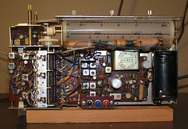
Below is another picture of the top of the chassis.
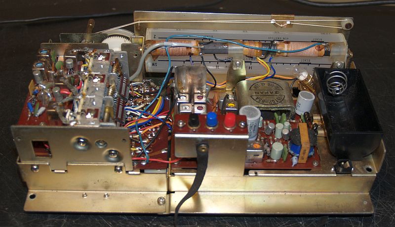
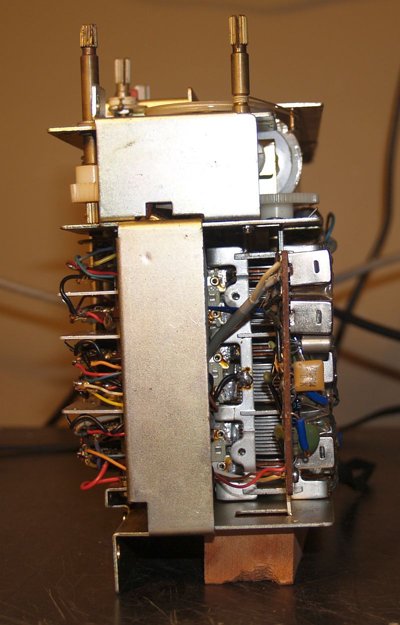
Below is a picture of the other side of the chassis as seen when the chassis is removed from the enclosure.
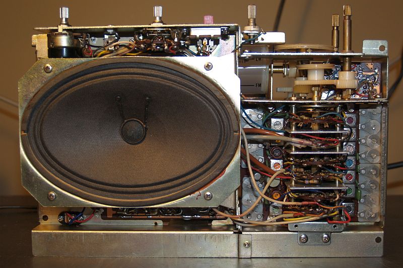
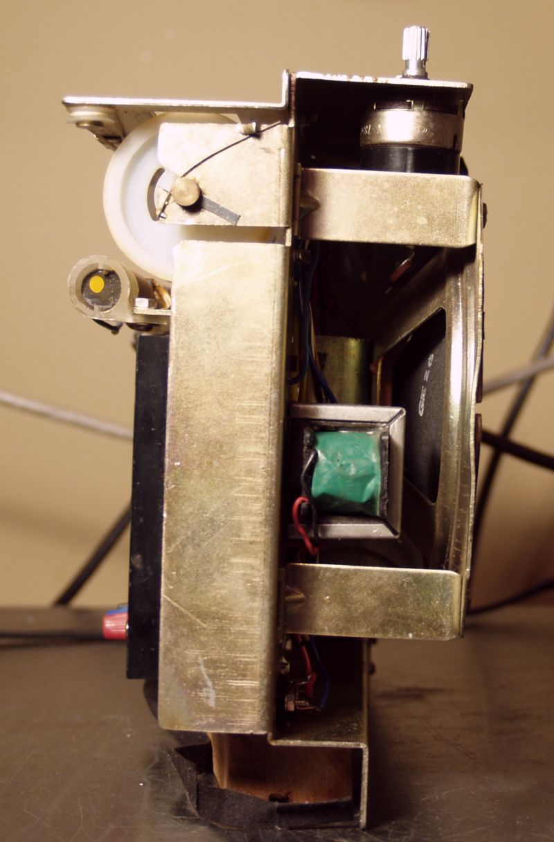
Below are two pictures of the ends of the chassis.
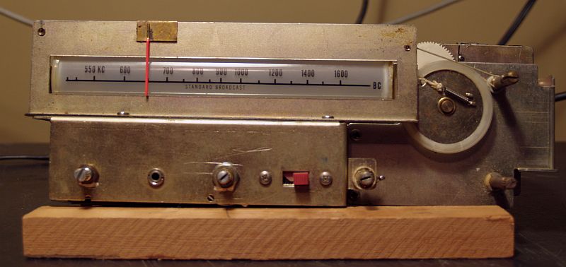
Below is a picture of chassis showing the dial and controls.
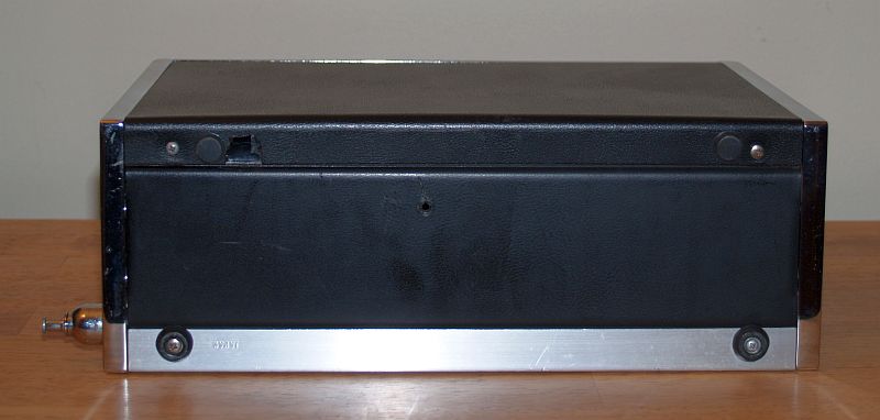
Below is a picture of the bottom of the radio.Not that the bottom is stamped with the word "Japan" indicating the radio was made in Japanfor Hallicrafters.
Other pictuers of the radio are below.