Below is a closeup of the face of the instrument.
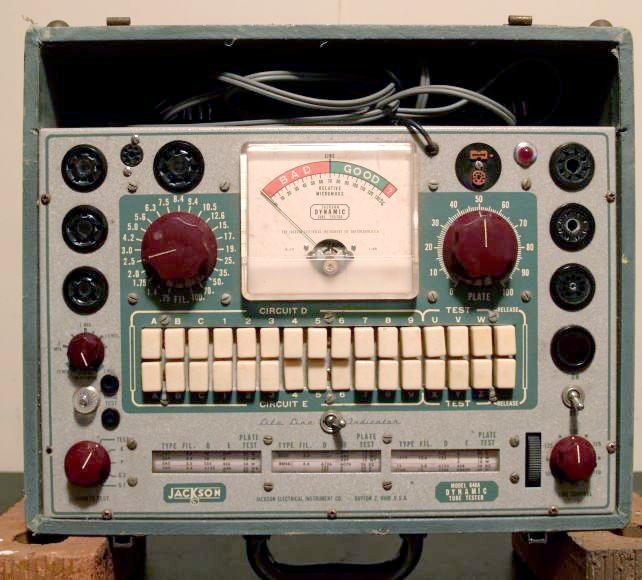
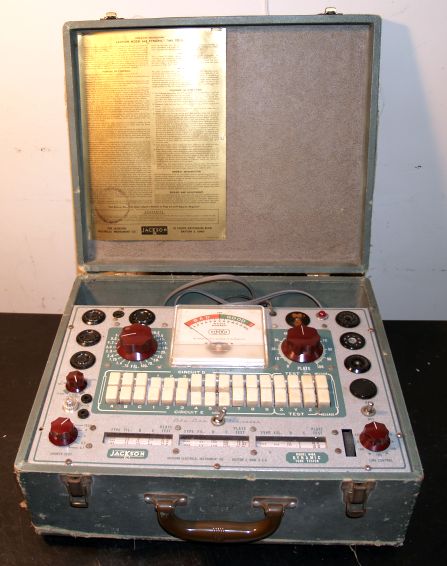
The instrument is turned on with the toggle switch on the lower right. After turning it on, you adjust the knob on the lower left to where the meter points to the center of the scale where "LINE" is written. This adjustment accomodates for differences in ac line voltages and its accuracy is critical to ensure accurate tube emission measurements.
Other controls include:
Filament voltage(upper left)(adjustable from 0.75 to 100 V)
Load (upper right)(Plate)for the tube for emission tests
Test for leakage and noise (center left)
Test for shorts (center left)
Pushbuttons in the lower center to select the test circuit
Test for emisssion with low filament voltage ("Lifeline" toggle switch below pushbutton bank)
Below is a picture of the inside of the instrument.
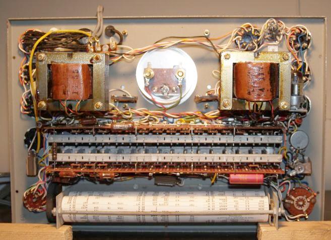
The circuitry is extensive but fairly simple. You can see two transformers on either side and the meter in the center between the transformers. There is one vacuum tube in the circuit. It is a 1S5 type and is located adjacent to the transformer on the right hand side. There is an electrical schematic stapled to the bottom of the woooden case. A picture of the schematic is shown below.
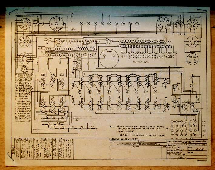
As you can see by the schematic, the circuit is extensive but simple. The two transformers have multiple taps. The schematic is dated 4-1-48 so the original design was developed in 1948. However, note the revision block in the lower left. It shows the last revision date of 8-30-56, so this instrument was probably made sometime after 1956.
The tester appears to work well. I have tested several tubes both good and questionable and it appears to give accurate readings. The tester was supplied with several adapters that are stored in the trough above the meter.