King Radio TRF Set Model D
This is a Tuned Radio Frequency (TRF) battery radio made by (I think) King Radio of
Buffalo, NY. There is no nomenclature on the radio indicating the manufacturer
other than the King logo stamped onto the stators of the 3 tuning capacitors. A plate
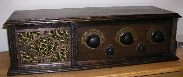
on the chassis indicates that it is a Model D. It has a built-in diaphram-type horn speaker on the left. Three
large knobs on the front tune three tuned circuits. All three circuits must be
identically tuned for best reception. The dials around the three knobs are calibrated 0 -100.
Volume is adjusted by varying the filament voltage using the lower left smaller knob (rheostat).
The right lower knob does nothing as its associated rheostat has no wiper. The resistance of
its rheostat is in the circuit only to drop voltage. Detection is is accomplished using a grid-leak detector. This radio is battery powered. The batteries used are:
A: 5V
B: 90V
C: 45V
D: -1.5V
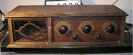
This radio was a mess when I purchased it. The finish on it was in terrible shape.
The fabric covering the speaker opening was almost all rotten away and a mud dauber
had built a nest inside the speaker reproducer. I cleaned it all up, stripped off
the old finish, refinished it using Tung Oil, and replaced the fabric covering
the speaker opening with a reproduction grill cloth that was similar to the
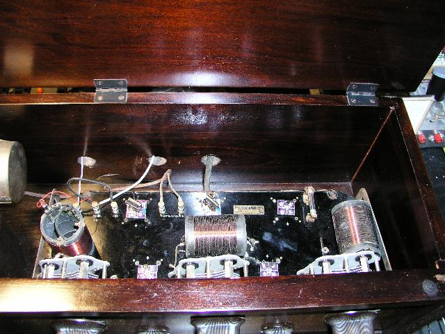
remaining pieces of the original. The audio intercoupling transformers had been replaced
at some time in the past, but the replacements had open windings on all primary and
secondary windings. Also, the wires connecting the batteries were quite frayed.
As an experiment, I made some FET replacements for the tubes after replacing the transformers.
I mounted all of the transistors on 4-prong plugs so that they would plug into the
tube sockets without requiring modifications to the original circuit. I did not use the higher
B+ voltages for the RF and detector stages; I used a variable dc supply (+15V max).
I had to use +90 Vdc for the audio stages to get sufficient signal amplitude to drive
the diaphram speaker that has a very high input impedance. Volume control
is accomplished by varying the dc vvoltages. This experiment works
reasonably well although the circuit has a bit too much gain as it will oscillate under
some tuning settings. Below is a picture before restoration. Below it is a view of the
inside with the transistor substitutes.
Tube Compliment |
| Ballast |
Rectifier |
RF |
Osc |
Osc/Mix |
IF |
Det/AVC |
1st Audio |
Audio Output |
Tuning Eye |
Rider's Manual Page # |
| N/A |
N/A |
2 x 201A |
N/A |
N/A |
N/A |
201A |
201A |
201A? |
N/A |
N/A |