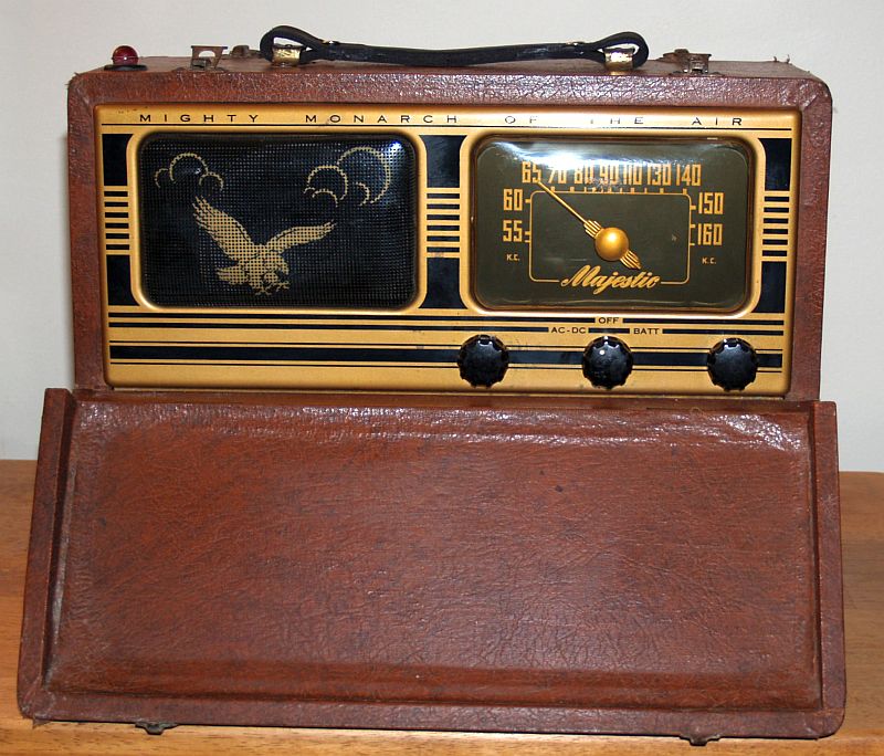
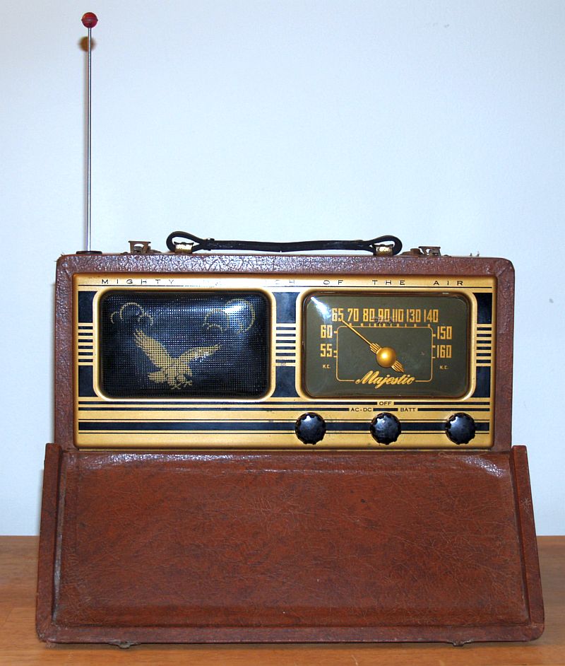
| ON-AC/DC OFF BATTERY (center) |
| TUNING (right) |
| VOLUME (left) |
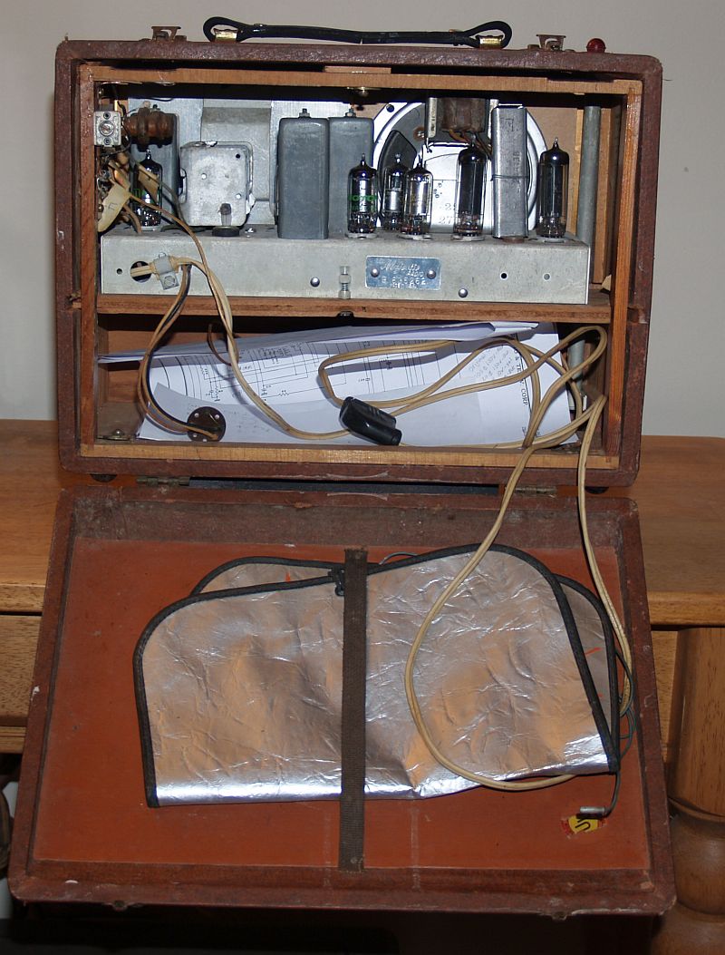
The rear of the radio with the rear cover opened is shown below. I placed the schematic and repair notes inside the cabinet.
The receiver features three built-in antennas - one is a wire loop antenna formed on a wooden rectangular frame. The frame is rectangular and mounted inside the enclosure. It is held in place by three hooks and screws similar to hooks and screws that held in place window screens of that period. The loop antenna is tuned by a coil and variable mica compression capacitor during alignment. The coil is shown below.
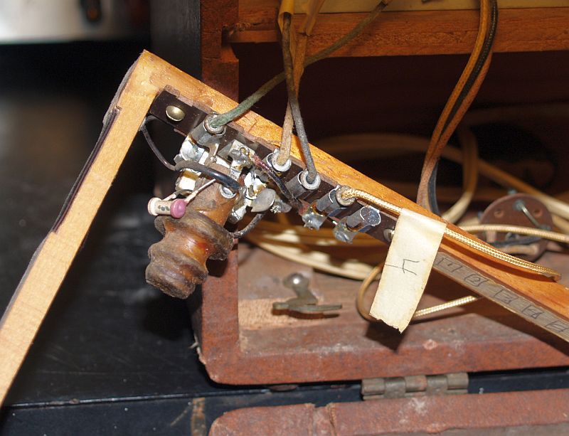
Another antenna is a telescoping rod antenna. The antenna inside the cabinet can be seen on the right in a previous picture and in the picture below with the antenna partially extended.
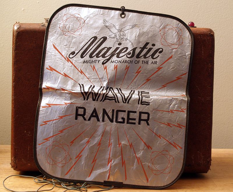
The third antenna is a metal sheet "Wave Ranger" antenna that is stored under a strap on the inside of the back cover. A picture of the "Wave Ranger" antenna is shown below.
All antennas are connected to the chassis via pins inserted into a row of terminal "sockets" on the loop antenna frame.
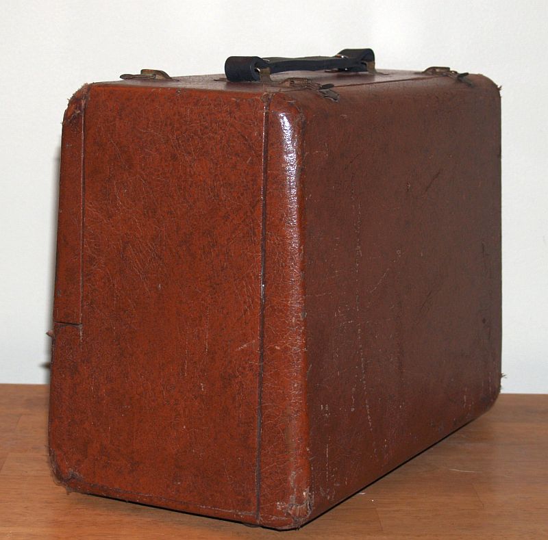
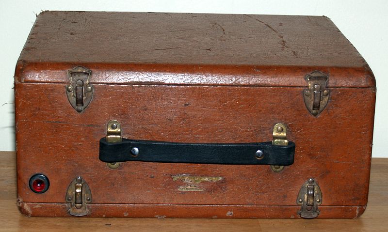
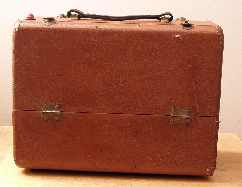
The receiver is contained in a wood cabinet covered with a thin leather sheet. When I received the radio, the leather was scratched in numerous places and there were tears in the leather. I rubbed brown shoe polish over the leather to improve its appearance. I did not patch the leather. The result is shown in the pictures. I also fabricated a leather handle to replace the original one that was missing. The new leather handle can be seen in the picture below. Note that the original nameplae is mostly missing. The front fold-down cover and the rear cover are held in place with metal hinges and latches. These metal components were orignally gold-plated. I did not restore them to their original appearance.
When I received this radio, the radio had a bad multi-element power supply filter capacitor and two bad 1U4 vacuum tubes. Replacing those parts brought the radio back to life. The original bottom-side of the chassis with the original filter capacitor is shown below.
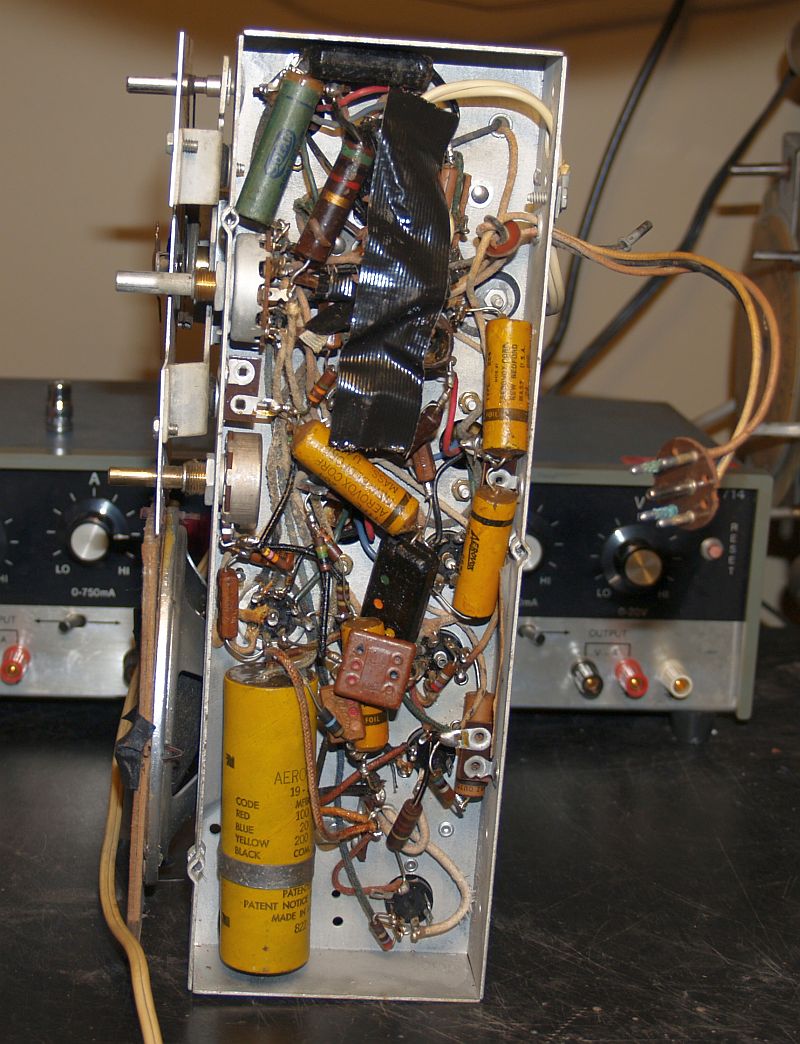
The large multi-element filter capacitor manufactured by Aerovox is the large cylindrical tan-colored object in the lower left. I replaced it with three modern electrolytic capacitors. I mounted a small terminal strip to the chassis using existing holes to rigidly fix the new capacitors. The other components, although old, appeared to be good. The radio plays well now with good tone.
The circuit is unusual in that it has two individual audio output tubes - a 3Q4 for use on battery power, and a 50B5 for use on ac power. A 35W4 is a rectifier for use on ac.
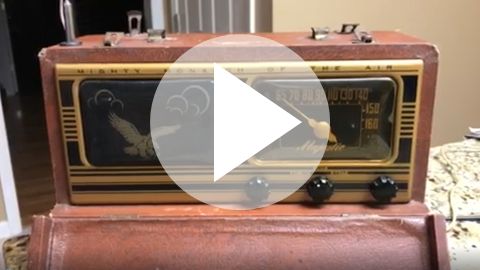
You can hear the radio receiving and playing a segment from the Grand Ole Opry by clicking on the image below. The file is large.
The front of the radio with the front cover closed is shown below.
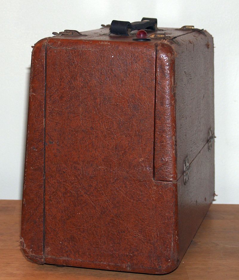
The sides of the radio are shown below.