At one time, Minerva advertised this radio was supplied to the US Navy and Army as a "Morale Radio" to be used for entertainment in barracks or other locations during WWII. However, most of these radios were sold after WWII.
The circuit is a superheterodyne configuration with an intermediate frequency (IF) of 455 kc. The set has no power transformer - it is an ac-dc circuit with one side of the chassis connected to the ac mains through a small-value resistor. The radio chassis is isolated from the metal cabinet by four phenolic spacers used to attach the rear panel and front panel to the chassis.
The example above is one of the early versions and this version uses two 25L6 audio output tubes as a push-pull amplifier with their filaments wired in series. An earlier version used two 50L6 tubes in the push-pull circuit with their filaments wired in parallel.
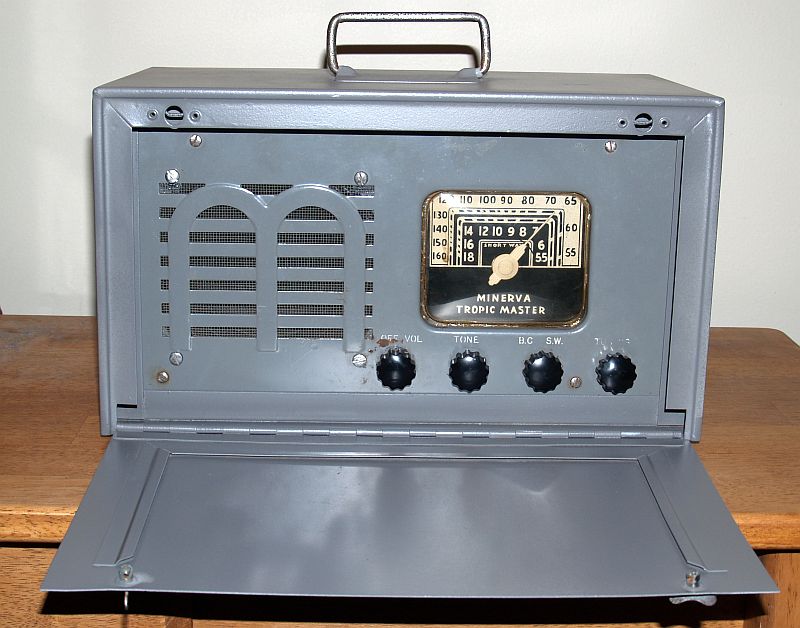
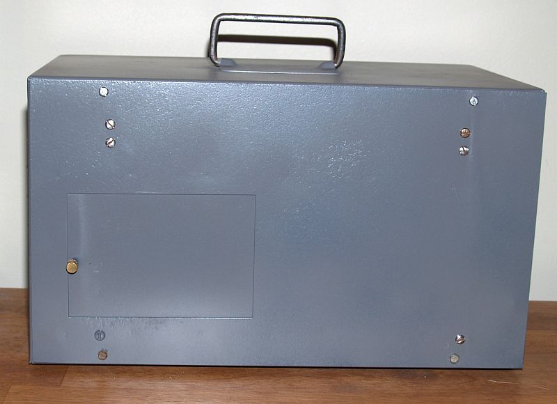
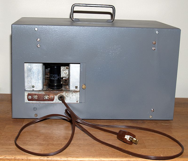
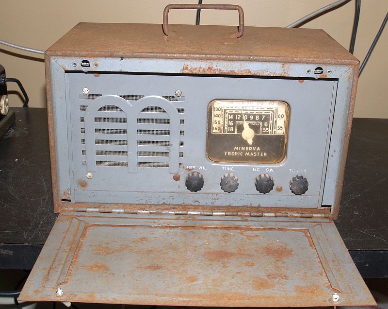
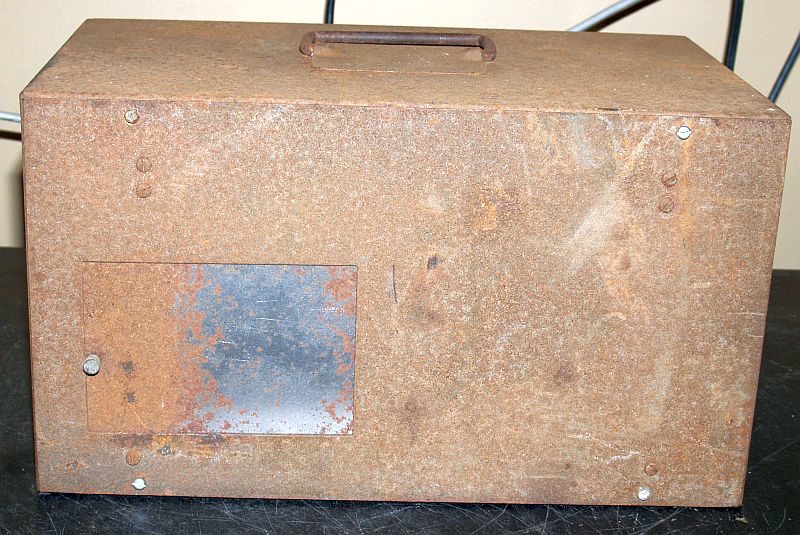
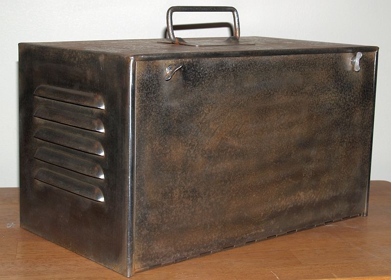
Four controls on the front are Volume/On-Off, Tone, Band Select, and Tuning. The rear of the radio has little sliding door to allow stowage of the power cord inside and access to the screw terminals for the antenna and ground. The pictures below show the door closed and open with the power cord.
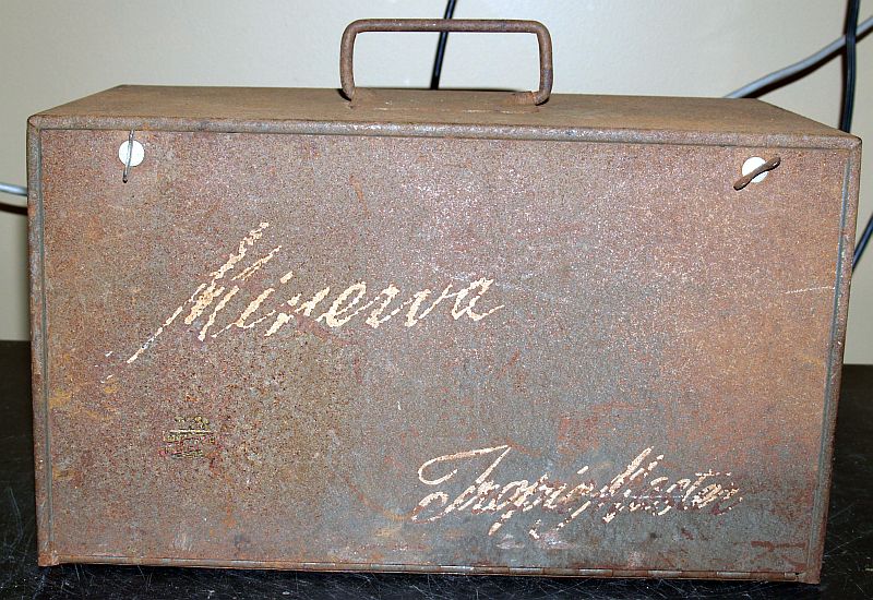
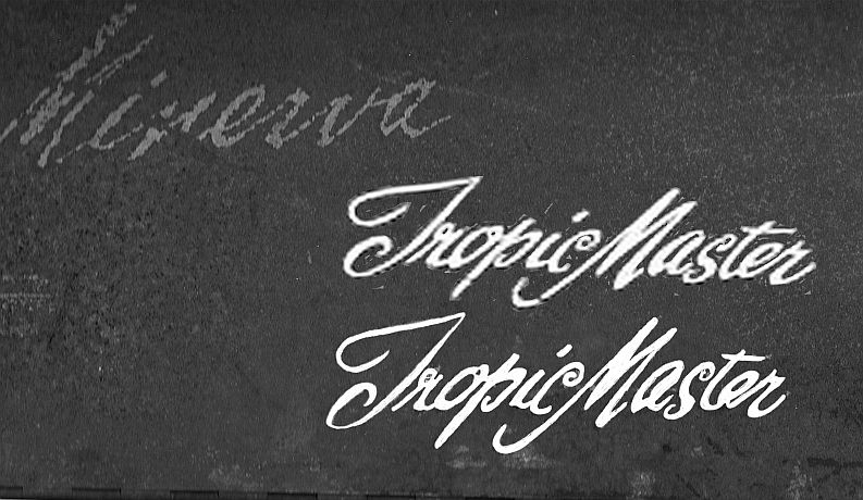
When I received this radio, it was extremely rusty as can be seen in the pictures below. But remnants of the original logos were present.
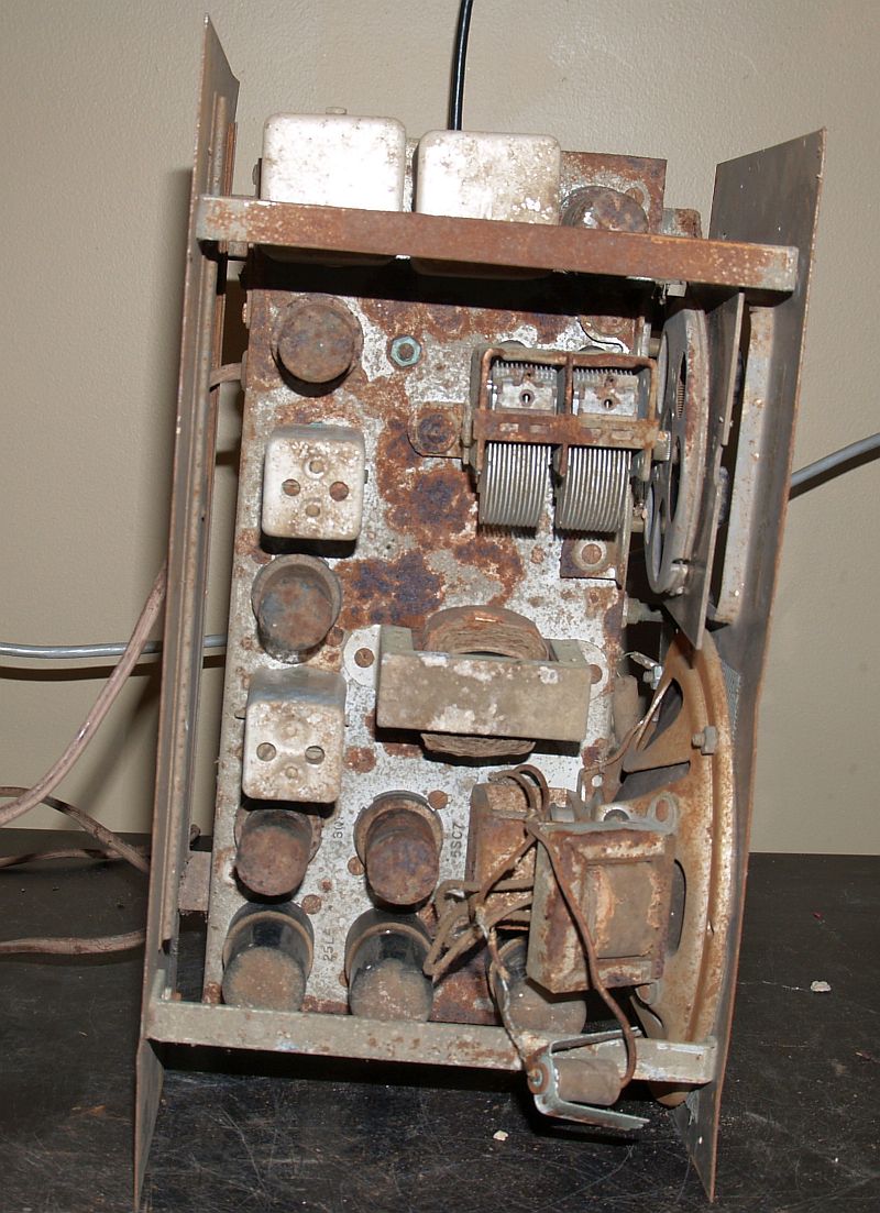
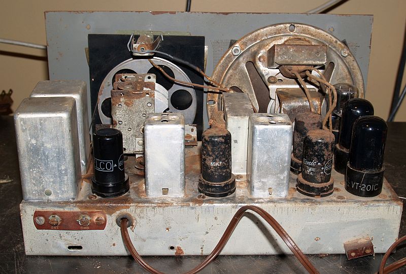
The chassis, when removed from the enclosure, was extremely rusty; even the metal tubes were quite rusty as can be seen below.
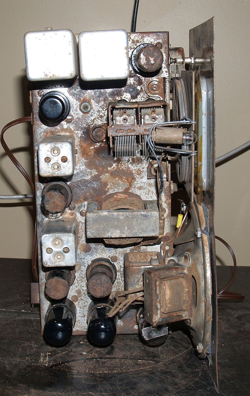
The picture below shows the underside of the chassis when received.
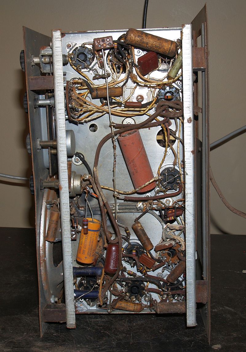 >
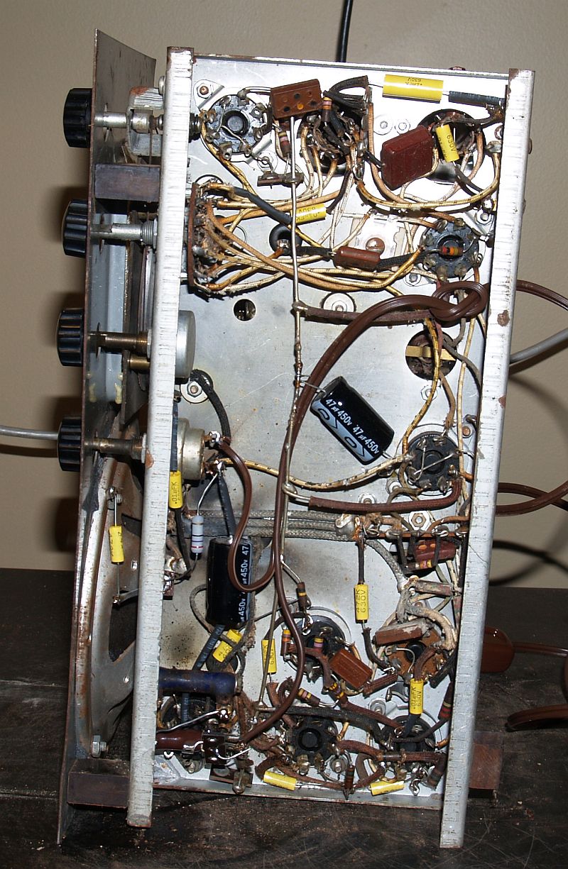
>There was not much rust on the underside of the chassis but there was a broken resistor. I changed out all of the capacitors and replaced the broken resistor, replaced a resistor in the power supply that was bad, and I replaced the power cord. One of the shielded coil assemblies had become unfastened inside the shield, and I repaired it so I could get the dial to read correctly on one band. The refurbished underside of the chassis is shown below.
The radio had one bad tube - one of the rusty ones, the 6SA7. The other tubes were good, even the other rusty tubes. I cleaned the rust from the top of the chassis as best I could. I had to devise a way to hold the dial lamp in place as the original lamp bracket was broken on one end. I used a wire to hold it in place. The result is shown below.
Below is a view of the rear of the chassis after restoration.
Refurbishing the cabinet took some work. I removed the rust by soaking the cabinet in white cleaning vinegar. This effort took several weeks as I had to soak each side individually. The vinegar worked very well and I scraped the rust off when the vinegar had done its job. After the rust was off, I used a brass brush in a drill motor to remove the remaining rust. The result is shown below.
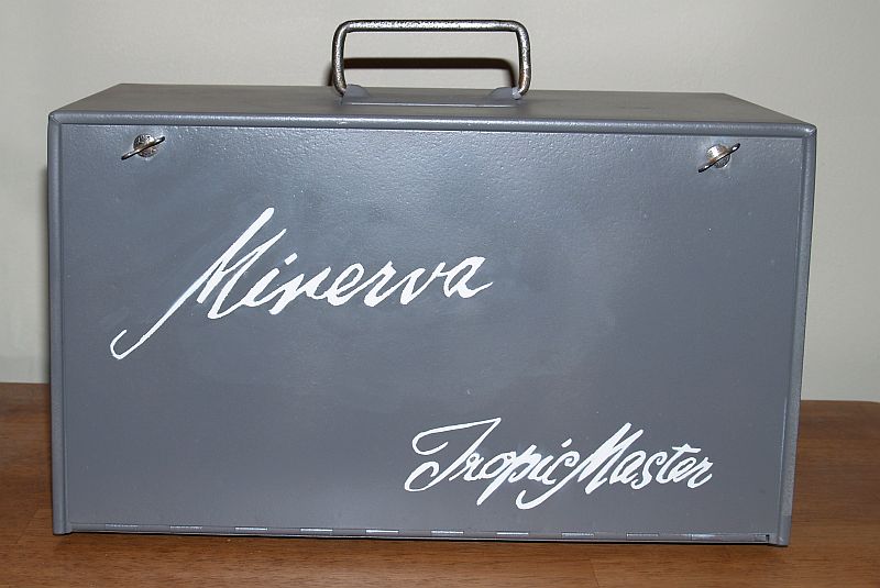
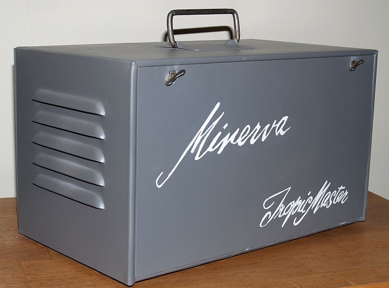
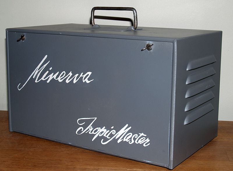
I primed all surfaces of the cabinet using Rust-Oleum self etching primer. Because the external surfaces of the cabinet had some amount of rust pitting, I then primed all external cabinet surfaces with Rust-Oleum filler primer. Then I painted all external surfaces with Rust-Oleum Satin Granite pant+primer. Applying the two logos took some thought. Before I stripped the rust (and remnants of the original logos) off, I scanned the front panel using my scanner printer. And I measured the locations of the logos, so I could put the new logos in the correct places. Below is a picture of the front panel with dimensions for the logo placement.
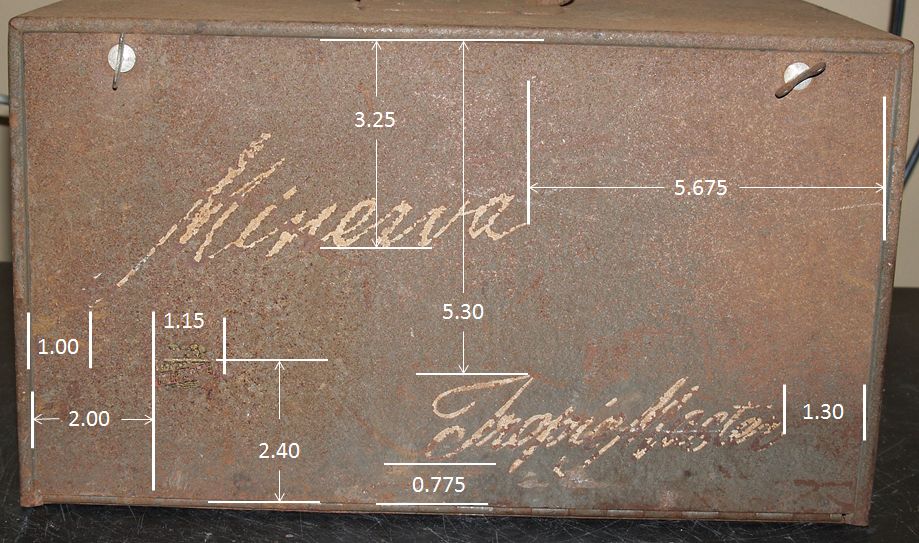
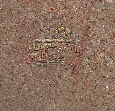
The front panel had a decal in the lower left-hand corner. In the picture above, I did measure the position of it, but too much of it was gone to reproduce it. Below is a closeup of it from the scanned image.
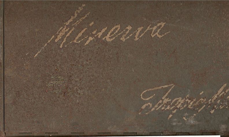
I applied the new logos using stencils I made from the scanned image above along with pictures of other similar radios I found on the internet. The pictures below show the scanned-in images. Note these images on this web page are reduced from actual size.
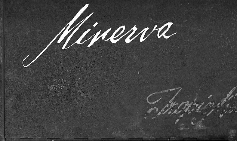
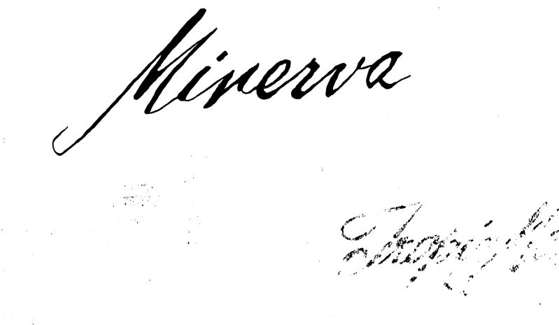
Using the scanned images, I used an image processing program (Gimp) to make a grayscale of the images and trace the scanned images to make them solid as shown in the pictures below.
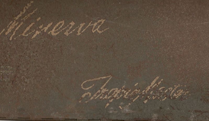
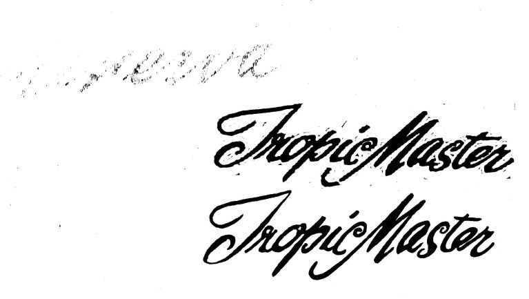
The "TropicMaster" logo was so far gone such that there was not enough of it remaining for me to figure out all the details details. I found an image on the internet and pasted it above the original scanned image and filled in the missing details by using the pasted image for reference.
The traced images were white, so when finished, I inverted the image (made a negative) resulting in black lettering on a white background. Then I increased the contrast significantly to make a sharp black-on-white image. The pictures below shows the result.
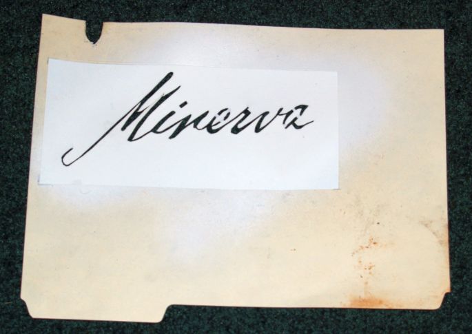
I printed the images out on paper, cut the images out, and glued the images onto a manila file folder using a spray adhesive. Then I cut out the images using a hobby knife. The two stencils are shown below.
 >
>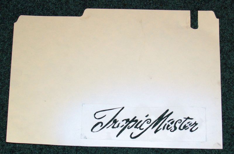 >
>Note that because these are stencils, some of the letters that encircle an area (such as an "O") must have "spokes" across the letter to hold the inner part in place. After the logo is painted on, I had to touch up the lettering to paint over the unpainted "spokes." Note the stencils have cutouts at the top of the mainila folder. These cutouts are used to position the stencils in the proper place relative to the two "twist locks" at the top of the front cover. And the logo are spaced relative to one side and/or the bottom of the manila folder to aid in positioning the stencils relative to the edges of the front cover.
I used Rust-Oleum satin Heirloom White spray paint for the logos. Before laying the stencils on the front cover, I lightly sprayed the back of the stencil with Krylon Easy-Tack repositional adhesive #7020 to ensure all of the parts of the stencil would lie securely on the surface to prevent any underspray.
I did not refurbish the front panel of the radio because there was not much rust on it. There are a few rust spots on it and the lettering above the controls are worn, but I wanted to leave it as I received it to show its age.
The pictures at the beginning of this webpage are the results of my cabinet refurbishment.
The radio works fine now and the audio quality is quite good with plenty of volume.