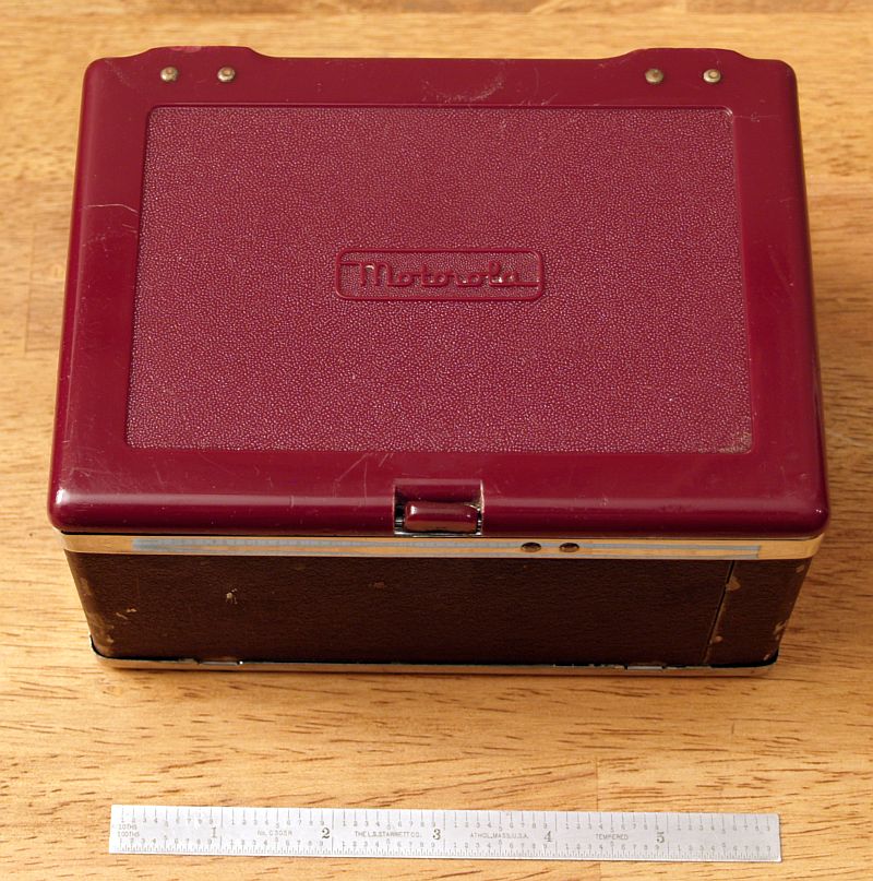
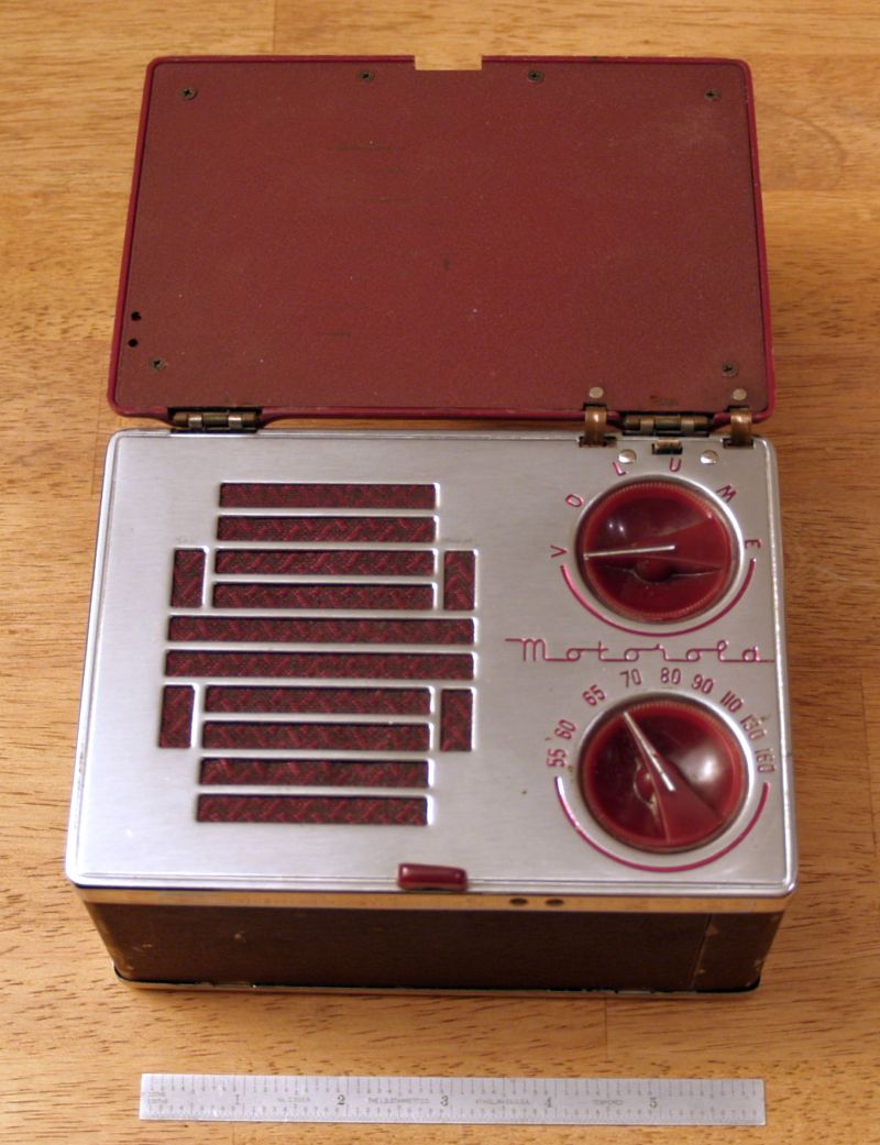
The radio is a "lunchbox" style radio and measures about 6.25 inches wide, 4.75 inches high, and 3.5 inches deep. The lid is spring-loaded and flips up when the tab at the center on the lower side is pulled slightly out. The loop antenna is contained within the maroon-colored plastic lid. When the lid opens, the on/off switch is closed and the radio turns on. The radio has only two controls - volume and tuning, both maroon-colored plastic. The speaker grill is adjacent to the conrols and is made of brushed metal. The radio has chrome trim. The case of the radio has a darker maroon color matte/crinkle finish.
The radio runs on three dry cell batteries - two 1.5 V batteries wired in parallel for the tube filaments, and one 67.7 V battery for the B+. The 1.5 D-cell batteries and contained within a metal holder while the larger 67.5 V battery uses snap contacts (similar to, but larger than a 9 V battery snap contact) and lays loose in the radio.
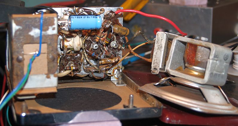
The radio did not work when I received it. It has an open 1M resistor in the plate circuit of the first audio tube. Also, one of the IF cans was loose as it was unsoldered from the chassis. The volume control was also somewhat intermittant. I also had to resolder the negative connection to the 1.5 batteries and make a cardboard insulator. However, all of the tubes were good. I fixed the above problems and replaced the 10uF bypass capacitor and aligned the radio. The radio works reasonably well and picks up numerous stations at night with reasonable volume.
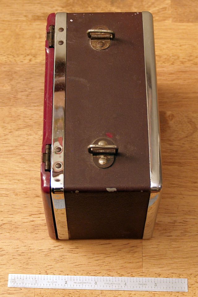
I cleaned the corrosion from the D-cell battery holdder and polished up the chrome and cleaned the plastic and the radio looks presentable as you can see in the above picture. The matte/crinckle finish is missing in several places on the case. In addition, the leather handle on top missing. The pictues below show the other sides of the radio.
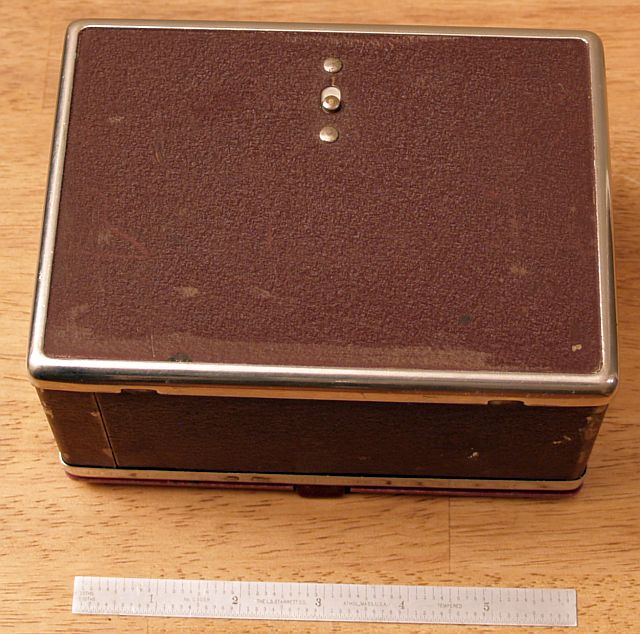
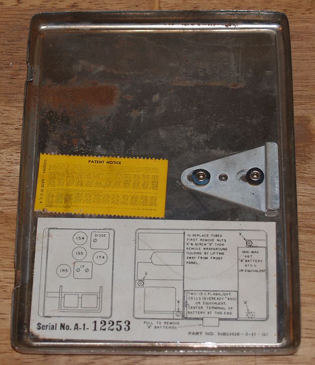
The back of the radio is removable for installing the batteries. A small button on the back is slid down to poen the latch and the back is pulled down and away from the case to remove the back. The picture below is a picture of the inside of the back cover. The inside of the back cover has the tube layout and instructions for installing the battery and replacing tubes. A serial number is shown, but the complete model number does not appear in the information.
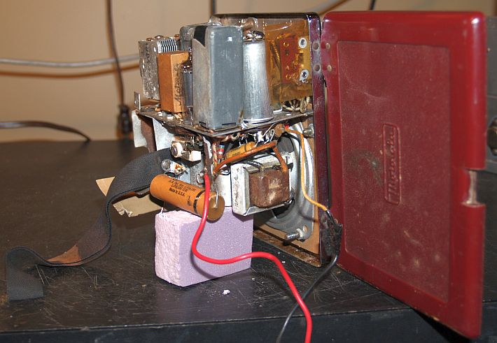
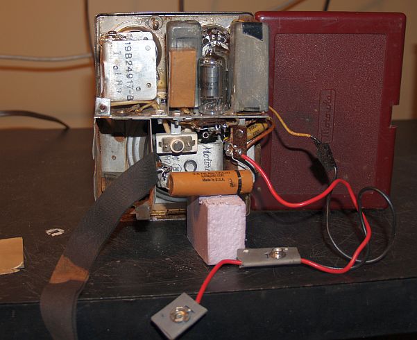
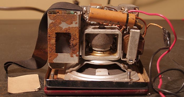
The pictures below show several views of the inside of the radio with the case removed.
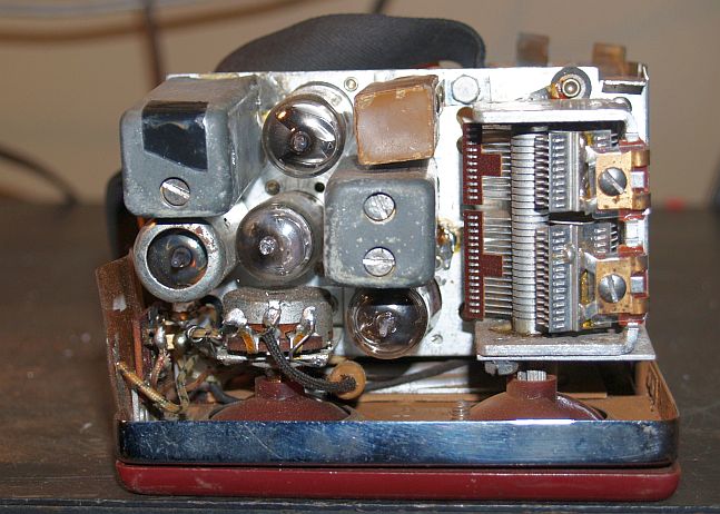
The radio circuit is a superheterodyne with an intermediate frequency (IF) of 455 MHz. The radio has 4 tubes as listed below.
It should be noted the Riders manual did not contain an electrical schematic. I found an electrical schematic in a Bietmans manual.