Motorola Model VT73 Television Television Receiver

As shown in the pictures below, the television sold for $199.95 in 1949.


Although the television is capable of tuning all 12 VHF channels, only 8 of the 12 channels are available at one time in the television. The channel selector has only 8 positions that tune channels 2 or 3, 4, 5, 6, 7, 8 or 9, 10 or 11, and 12 or 13. Four of the channel positions are pre-tuned to a local television channel at the factory or by a local service center or repair shop. My television has a tag on the rear of the chassis that specifies the channels to which the television is setup as seen in the picture below.
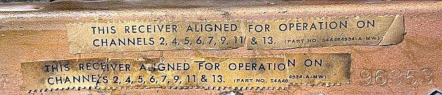
As seen in the picture above, my television is set up to receive channels 2,4,5,6,7,9,11,and 13.
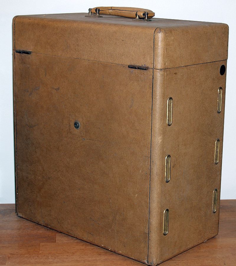
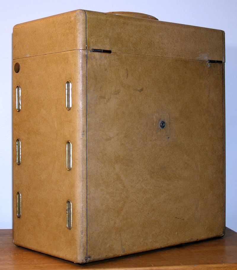
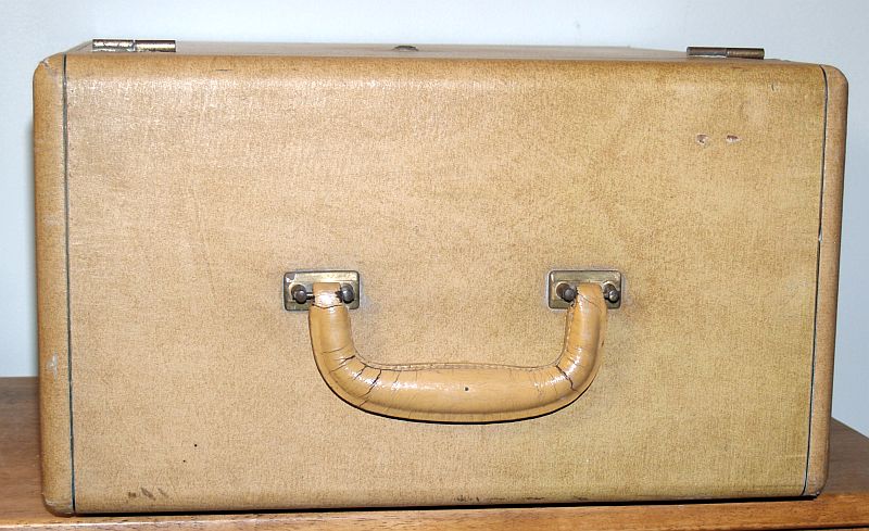
The television is a portable device housed in a light tan leatherette-covered cabinet with a leather handle on top. The television was supplied with a removable "rabbit ears" type antenna that is stored in the lid of the cabinet. The antenna can be plugged into a 1/4-inch phone jack on top of the television or plugged into a metal mount and placed away from the television and connected to the television with TV 300-ohm twin lead. The mount is stored in the lid of the cabinet along with the antenna as shown in the picture above.
The television is light-weight because it has no power transformer. All of the vacuum tube filaments are in two series parallel combinations. The television has a ballast resistor assembly (comprising four power resistors) that plugs into a tube socket to reduce the line voltage to that required for the dc power supply and tube filament strings. The television has two selenium rectifiers to produce the B+ voltage. The unit requires an isolation transformer for servicing.
The controls on the front panel include:
On/Off Switch and Volume Control
VHF Channel Selector Switch/Fine Tuning Control
Contrast Control
The controls on the rear include:
Focus
Horizontal Centering
Vertical Centering
Width Control
Height Control
Horizontal Hold
Vertical Hold
Brightness
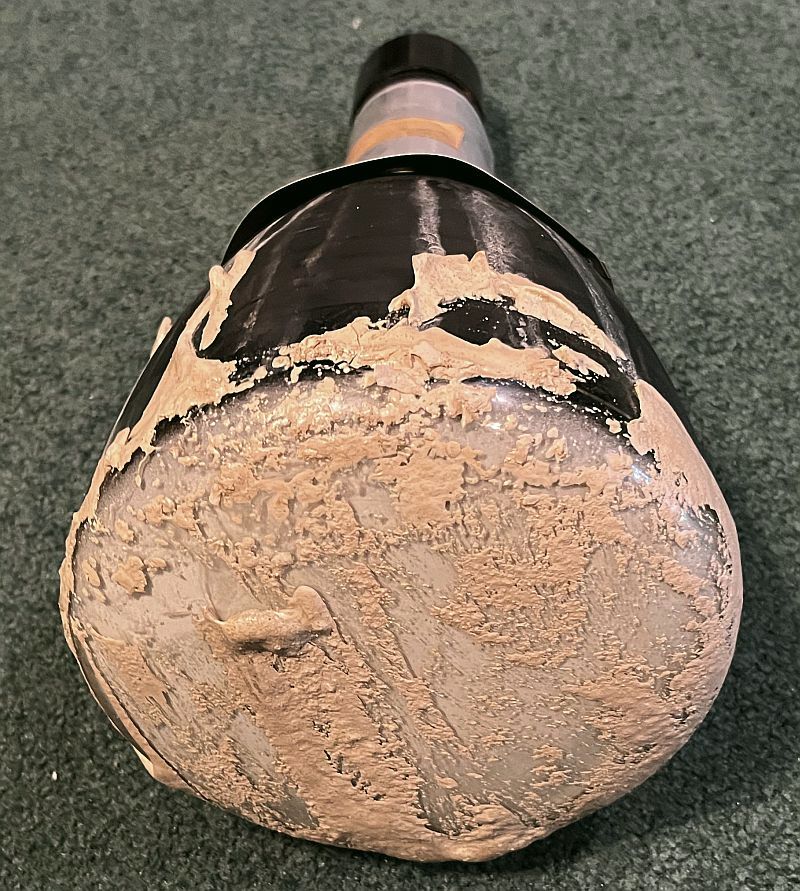
Although the television was in reasonably good condition when I received it, as shown in the pictures below, the original gasket or mask on the face of the cathode ray tube (CRT) had disentigrated over the years and "melted" and ran down the front of the CRT into the cabinet and then hardened. This situation clearly is evident in the first picture below showing the front of the television. This condition is a common occurrance with this television.

As typical with leatherette-covered cabinets, the television had a musty and moldy odor, especially when the top was opened.
The picture below shows the rear of the television with the rear cover removed.

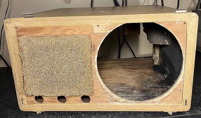
The picture below shows the front of the television with the plastic grill removed. To remove the grill, the chassis must be removed and one of the two horizontal pieces above and below the grill removed. The top horizontal piece is held in place by three flat-head screws accessed through the rear of the cabinet. The lower piece is held in place by two machine screws on both sides of the cabinet accessed by removing a round brass plug on the sides of the cabinet.
The gasket was some kind of a synthetic material. Fortunately, the material will soften and dissolve using tap water. Also fortunately, the hardened material firmly supported the front of the CRT and prevented it from bouncing around during movement of the television. The rear of the CRT is held in place only by a wooden mount to the top of the cabinet. When new, the original gasket provided support for the front of the CRT.
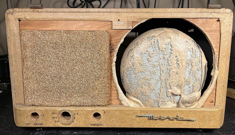
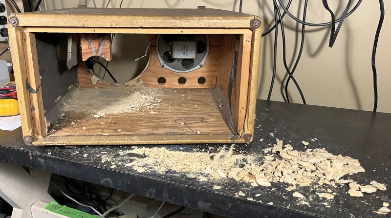
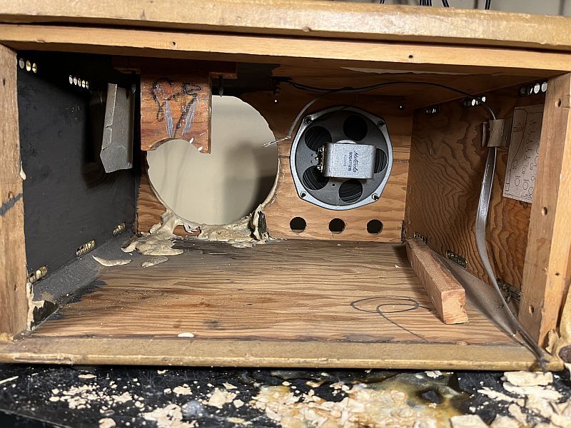
To remove the CRT, I squirted small amounts of water on the hardened gasket material around the front of the CRT. I was careful to not use too much water becasue I did not want to waterlog the wooden cabinet that is held together with glue. This took some time. It required repeated applications of water, carving out the material with a hobby knife, carving pockets to capture the water, and cutting out the softened material. The softened material is similar to putty. Eventually, the CRT was free of the cabinet and I could remove it. The picture below shows the cabinet with the CRT removed. You can see the hardened material stuck to the cabinet.
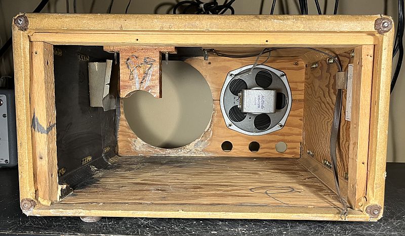
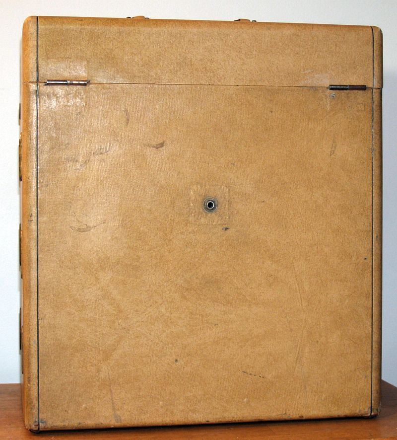
I cleaned the cabinet using small amounts of water, a hobby knife, and a Dremel tool with a brass brush. The hardened material could be popped loose with the hobby knife with some work. The pictures below show the cleaned cabinet.
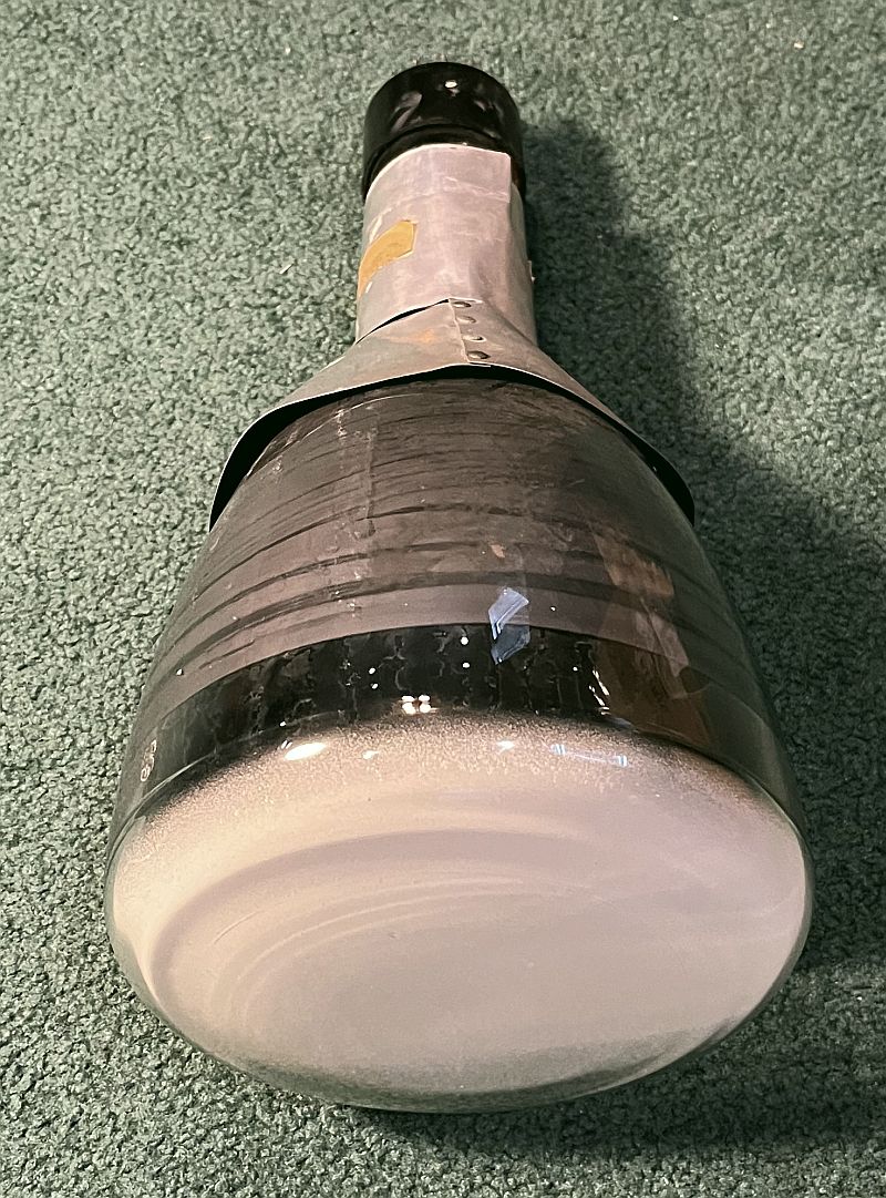
Below are pictures of the CRT covered with the hardened gasket material after removal from the cabinet.

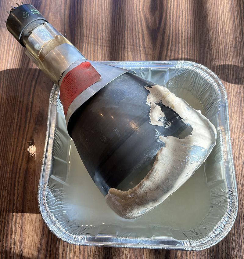
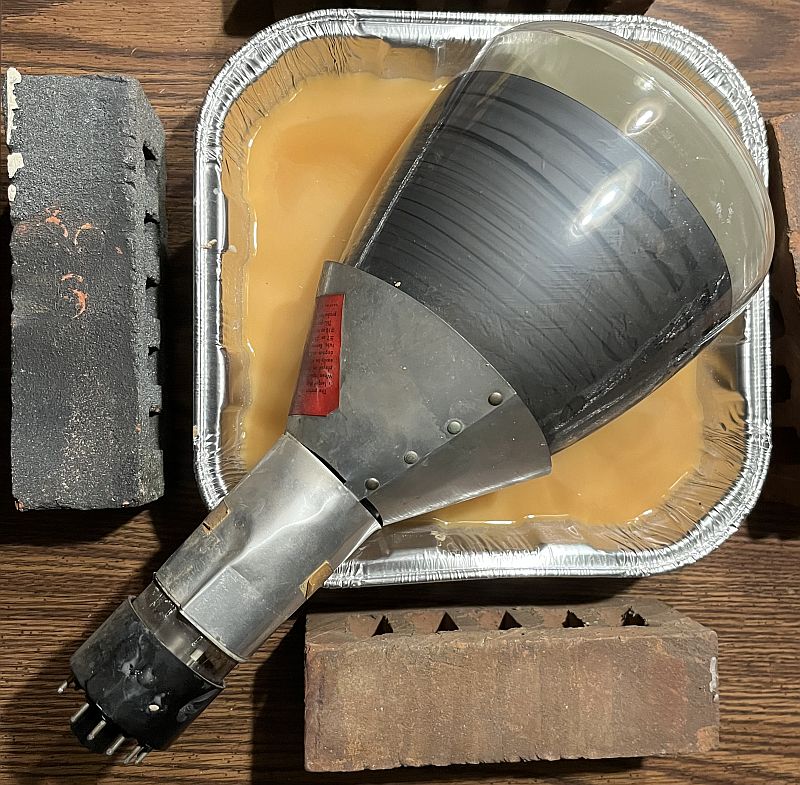
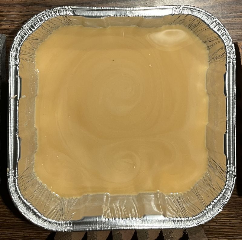
I soaked the CRT in a pan of water for a few days. The water dissolved the material and turned the water an orange color as seen below.
I used Windex to final-clean the CRT. The cleaned CRT is shown below.
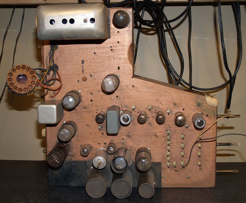
Below are pictures of the chassis as received.


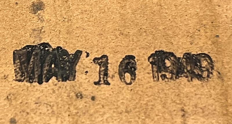
Below is a closeup picture of the date stamp on top of the chassis. The manufacture date is May 16, 1949.
Below is a picture of the high voltage oscillator with the cover over the coil and high voltage rectifier emoved.

The 25L6GT beam pentode vacuum tube that implements the high voltage oscillator is shown on the left and resides outside the metal cover. The 1B3GT high voltage rectifier vacuum tube is shown on the right and resides inside the metal cover with the coil. Note te 1B3GT high voltage rectifier vacuum tube has a coil loop around the glass envelope. This loop provides the feedback to the oscillator. The loop is glued to tape that surrounds the glass envelope. The position vertical position is critical to sustain oscillations. As such, it is challenging if one has to remove the 1B3GT vacuum tube for test or replacement. Therefore, I did not test that vacuum tube and hoped it was good as those tubes are fairly reliable anyway. It turned out that the 1B3GT vacuum tube was good.
All of the other vacuum tubes tested good. The 6AU6 video amplifier vacuum tube tested weak, the 6AG5 first video IF vacuum tue tested marginal, the 12AT7 converter vacuum tube tested weak, and the 25L6GT audio output vacuum tube tested weak. All vacuum tubes were tested on my TV-7 vacuum tube tester.
I replaced all of the wax paper and electrolytic capacitors. I left the original electrolytic capacitors in place and installed modern, and physically smaller capaciors underneath the chassis. I installed some of the eletrolytic capacitors using terminal strips; others I installed on existing circuit nodes. Because this television has no power transformer and the chassis is isolated from electric circuit ground, I wrapped all of the electrolytic capacitors in cardboard and labeled each with capacitance, working voltage, and its reference designator per the SAMS Photofact electrical schematic. The bottom of the restored chassis is shown below.

I replaced two selenium rectifiers with 1N5408 silicon diodes I mounted these diodes to a terminal strip as seen in the lower center part of the picture above.
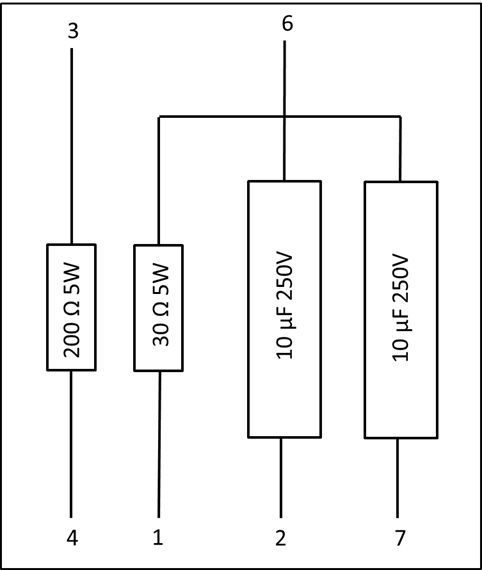
This telvision has a ballast assembly comprising two power resistors that reduce the line voltage for the parallel/series filaments and two resistors in the B+ voltage supply. Three of the four resistors measured open circuit. The Motorola part number for this ballast assembly is 17A485459. An elecrical schematic of the original 17A485459 ballast assembly is shown below.
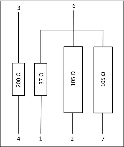
Note that three resistors have a common connection to pin 6. These three resistors measured open suggesting that the connection to pin 6 is open.
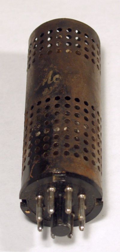
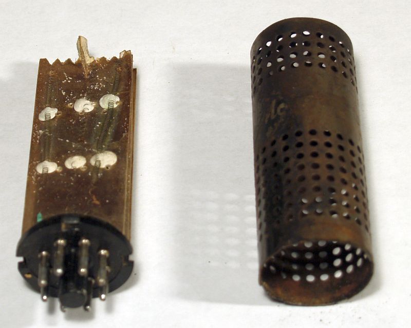
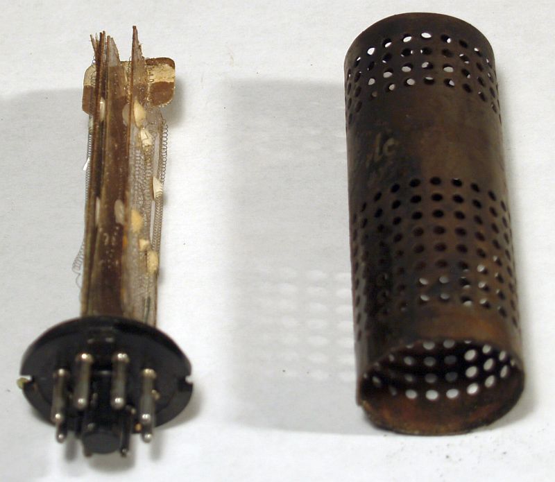
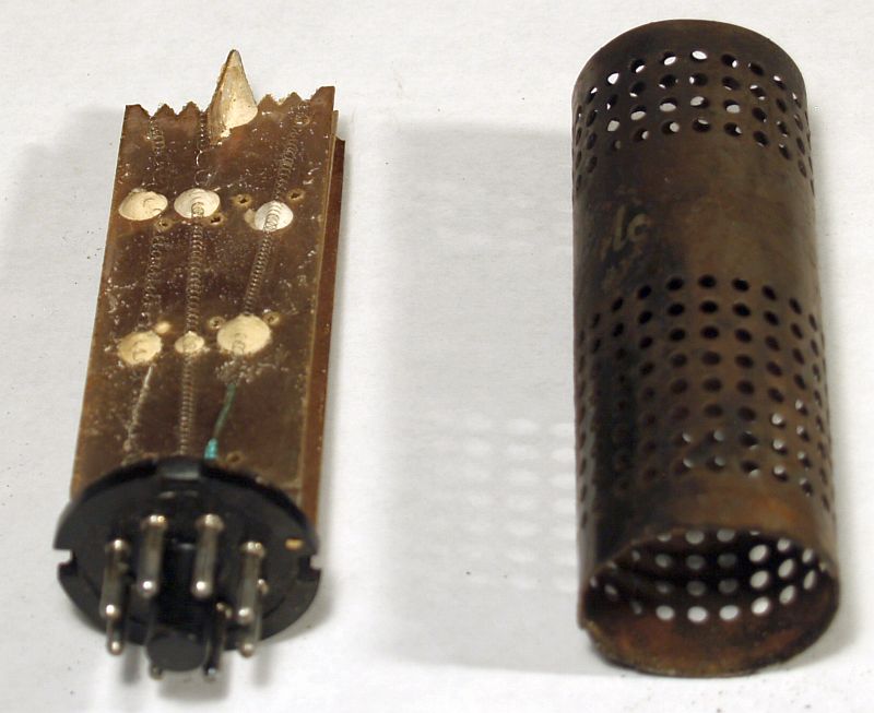
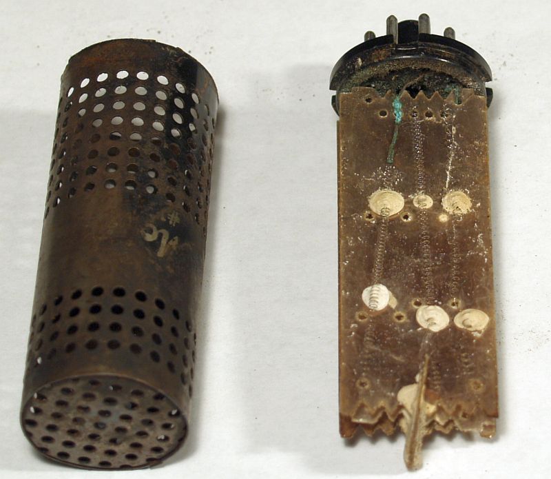
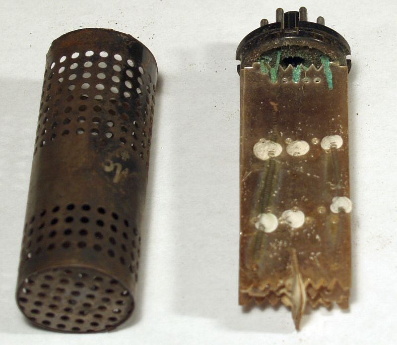
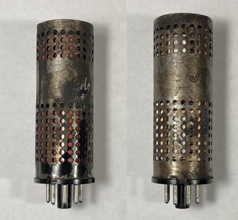
I decided to rebuild the ballast assembly rather that attempt to repair the original ballast. Below are pictures of the original ballast assembly. As shown, the original ballast assembly comprises resistance wires mounted on three mica sheets that would be difficult to repair.
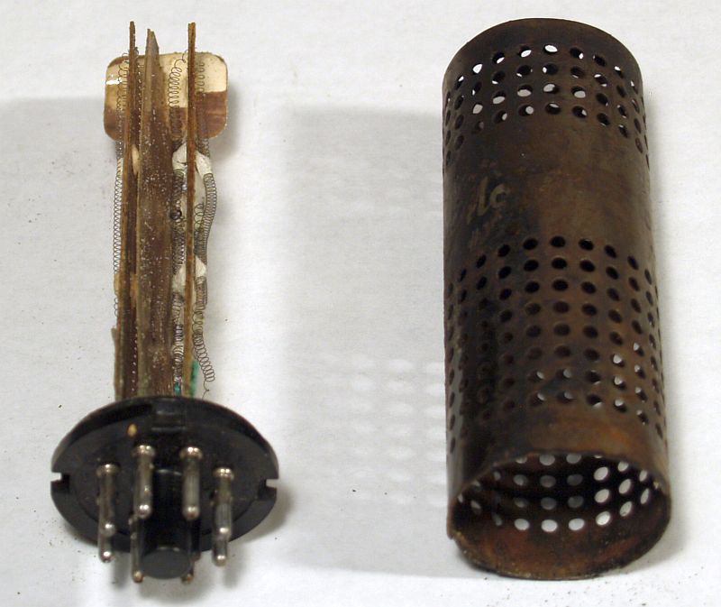
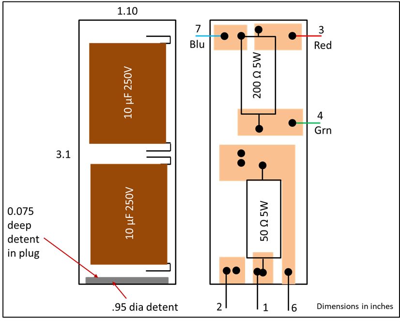
The original ballast assembly dissipates a lot of heat during operation. Numerous discussions on line have resulted in a redesigned ballast that dissipates much less heat. To implement a much more efficient ballast, the two 105-ohm resistors in series with the two filament strings are replaced with 10 uF film capacitors. The reactance of the two capacitors at 60 Hz reduces the voltage to the filaments instead of reducing the voltage by the curent-voltage drop through resistors. An elecrical schematic of the replacement 17A485459 ballast assembly is shown below.
In designing the replacement ballast, I mounted the two capacitors and resistors on a single-sided circuit board. I "etched" the circuit board using a Dremmel tool. I mounted the capacitors on the non-copper side, and mounted the resitors on the copper side. The layout of this assembly is shown below.
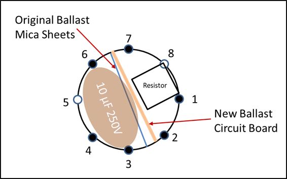
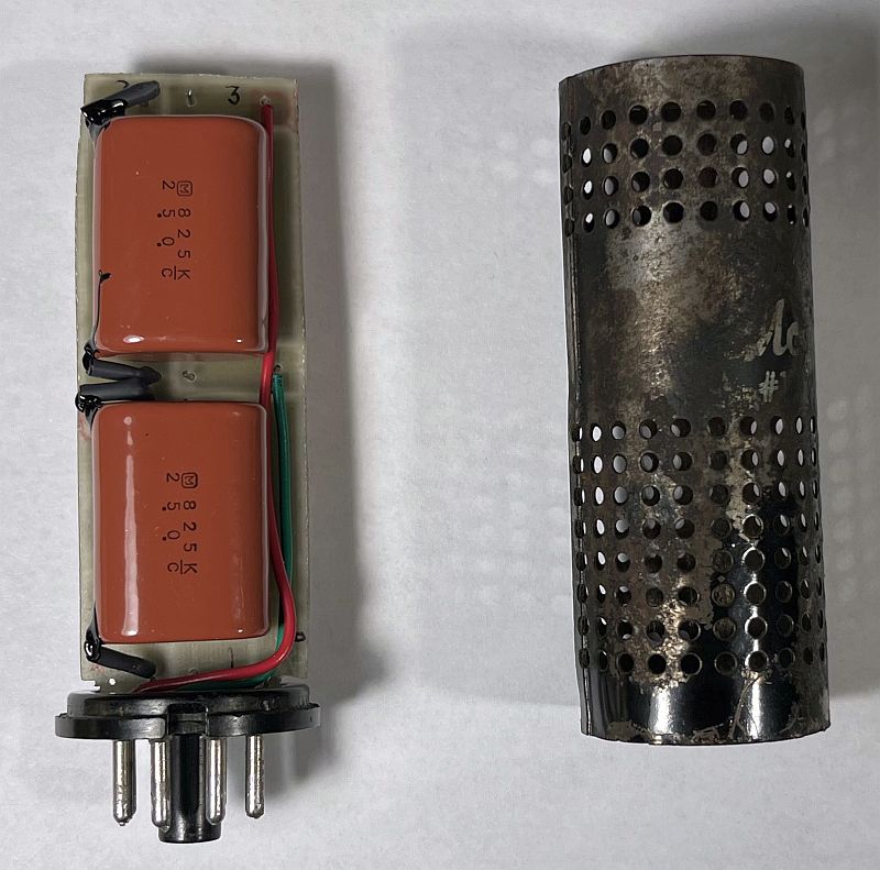
I used the original ballast 8-pin plug and metal perforated case. When mounting the above assembly onto the plug, I oriented the above assembly in much the same orientation as the original mica sheets as shown below.
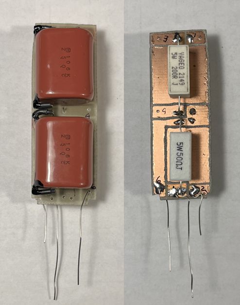
Below is a picture of the replacement ballast internal assembly.
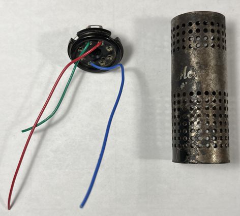
Below is a picture of the original ballast plug rewired for the replacement ballast.
Below is a picture of the repalcement ballast final assembly.
After restoring the chassis and inserting the new replacement ballast, I brought the television up slowly using a variable transformer and isolation transformer while monitoring the B+ voltge. I did not connect the CRT for this test. I substituted a 10-ohm power resistor (actually two, 20-ohm, 10-Watt power resistors in parallel; resistors I had on hand) for the CRT filament. The B+ voltage measurement was reasonable and I heard the 400-Hz audio tone produced by my B&K Television Analyst signal injected into the antenna terminal on the channel to which the television was tuned.
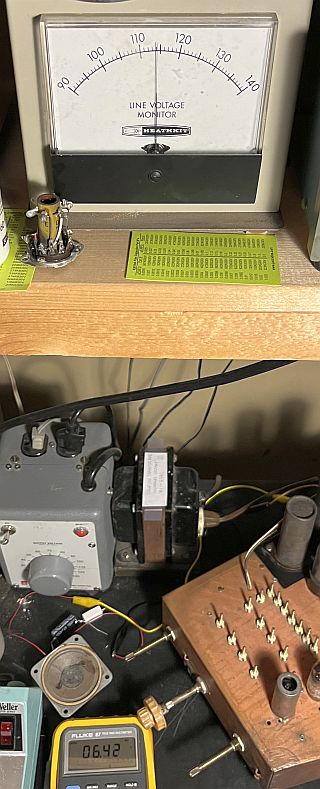
Then, I connected the CRT and slowly brought up the television using a variable transformer and isolation transformer while monitoring the ac filament voltage at the CRT. The picture below shows what appeard on the CRT.

The ac voltage for the CRT filament measured 6.42 VAC at a line voltage of 114 VAC as shown below. As such, the CRT filament voltage is a little high, especially if the television is operated at 120 VAC.
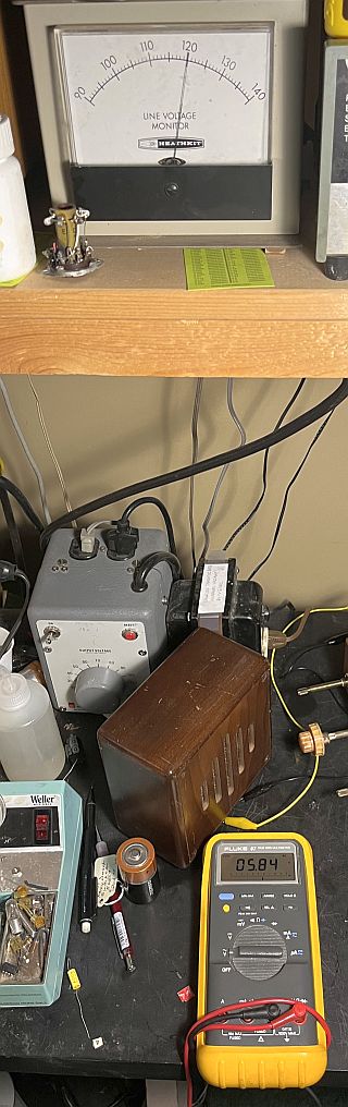
After getting the television to work properly as described below, I replaced the two 10 uF capacitors in the replacement ballast with 8.2 uF capacitors. The CRT filament voltage measured about 6 VAC at a line voltage of 120 VAC as shown below.
The revised replacement ballast assembly and layout is shown below.

Initially, the CRT produced only a line, indicating either the vertical or horizontal drive signal is not present. At the time, I was not sure of the proper orientation of the CRT outside of the cabinet.
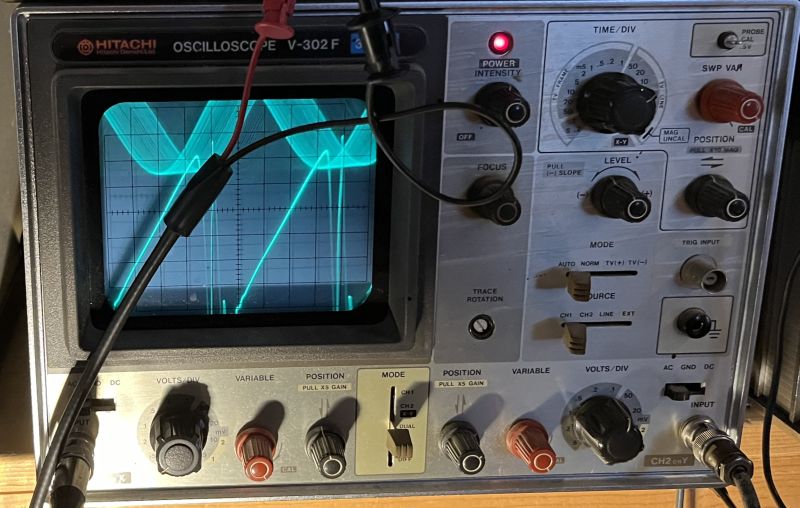
Investigation revealed the horizontal blocking oscillator was not producing a sawtooth ramp. Instead, a short pulsed signal was produced at a rate significantly higher that 15,750 Hz. After lengthy experimentation, I replaced the 680 pF and 200 pF capacitors in the horizontal blocking oscillator crcuit and the oscillator produced the expected sawtooth ramp signal as shown below. It is difficult to measure the frequency of a sawtooth with a frequeny counter. As such, I input a 15,750 Hz sinewave signal on one channel of the oscilloscope and insert the horizontal sweep signal on the other channel. The oscilloscope was syncronized to the ramp signal. As seen in the picture, the two signal are nearly in phase indicating their frequencies are nearly identical. The jitter indicated in the sinewave is most likely due to the television attempting to synchronize to noise. This test indicaed the television horizontal blocking oscillator is now operating properly. The above investigation was performed using the 10-ohm substitute for the CRT filament and the CRT disconnected.
Now that the horizontal blocking oscillator appeared to be operating properly, I reconnected the CRT and brought the television up slowly using a variable transformer and isolation transformer. The CRT produced the image below after some adjustments to the horizontal and vertical size and centering controls and focus control.
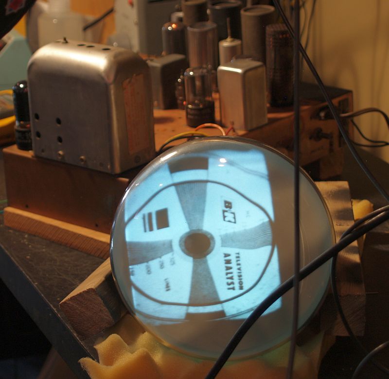
The image is not perfect and needs further investigation, but the CRT is good and produces a good image. This image was produced without replacing any of the original vacuum tubes.
The audio initially worked, but later on, no audio was produced. Investigation yielded that the volume potentiometer was intermittant. Spraying the wiper with Deoxit cured the problem.
Because my in-house television transmitter operates on Channel 12, I retuned the highest channel to Channel 12. It was originally tuned to Channel 13. I injected an amplitude-modulated RF signal at 205.25 MHz (the video carrier of Channel 12) and adjusted the slug of coil A16 (the local oscillator coil) to produce a maximum signal at the plate of the third video IF amplifier as seen on an oscilloscope. This was done with the fine tuning set for the maximum amplitude when I initially injected an RF signal at 211.25 MHz, the video carrier of Channel 13. Doing this ensured the fine tuning should have the same tuning range on Channel 12 as it did on Channel 13. I then adjusted A25 (RF coil) to maximize the signal. The picture below shows the two coils to adjust in order the retune the highest channel. Although my method is not what was described in the SAMS Photofact adjustment procedure, the television now receives on Channel 12 with good sensitivity.

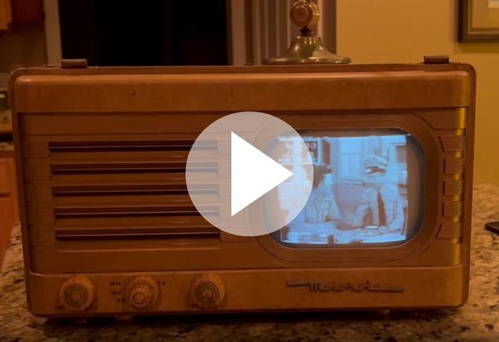
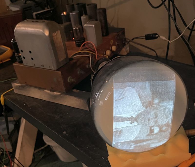
After adjusting the various controls on the telivision and interchanging the order of the vacuum tubes in the video IF strip to place the tube that tested strongest first, the television performs well on Channel 12. The picture below shows the television receiving a program on Channel 12.
Click on the image below to see a video of the television receiving the program above (Matlock).
Because the original CRT gasket/mask disintegrated, a replacement support for the CRT face is required. I glued 5/8 in. backer rod to the inside of the round cutout as shown below to support the CRT.


Below is a picture of the CRT reinstalled in the cabinet and supported by the backer rod.

The CRT is readily installed through the rear because the wooden upper trim piece is held in place by three screws that are difficult to access with the CRT in place. However, during initial disassembly, I did, with some difficulty, remove the three screws and trim piece with the CRT in place.
Before installing the CRT, the bottom foot underneath the CRT must be installed first. That foot does not secure the chassis; the foot has a shorted screw and is held in place with a nut plate. The nut is underneath the CRT and is inaccessable with the CRT in place.
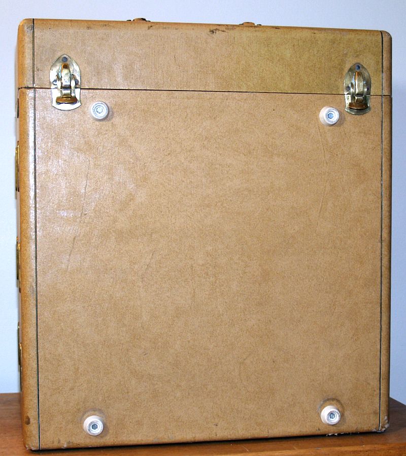
One of the original feet was missing when I received the television and the other three were quite stiff and cracked. I replaced all four feet with white 7/8 in. rubber bumbers manufactured by Everbilt.
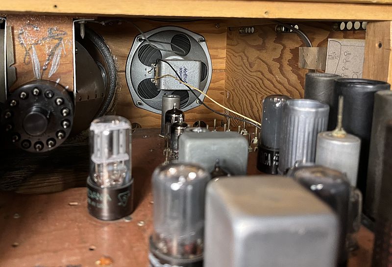
The speaker must be reconnected before the chassis is pushed all the way in. The two speaker leads from the chassis press into two receptacles on the speaker as shown below.
The chassis is held in place with three of the bottom feet screws.
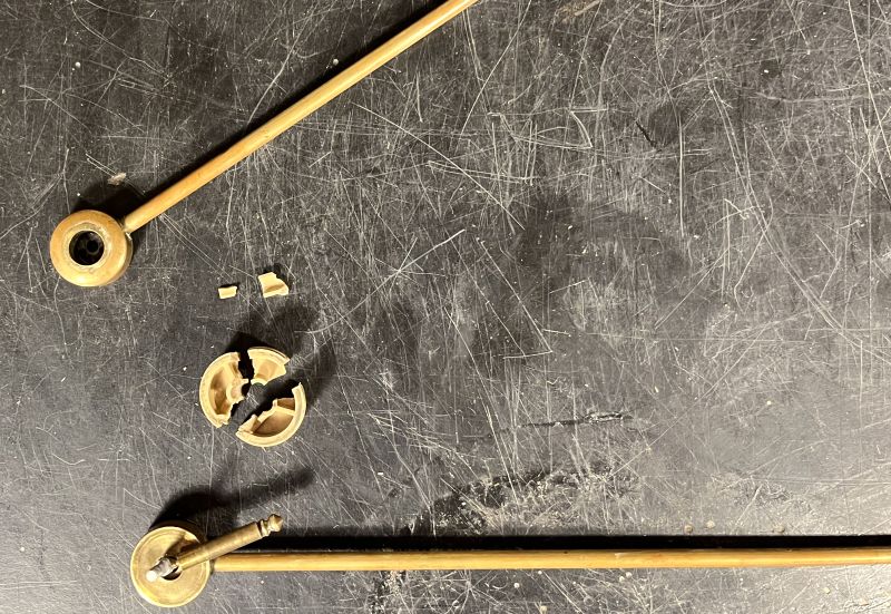
As shown in the first picture above, the televison came with its original antenna and its remote antenna mount and twin lead. The antenna has a 1/4 inch phone plug that can plug into a phone jack on top of the television or into a phone jack on the remote mount. The antenna is missing one of the plastic balls on top of one of the antenna elements. The plastic spacer between the two antenna elements was cracked as shown below. When the antenna elements are moved, the pieces of the broken spacer fall out.
In addition, there was no electrical connection between one of the antenna elements and the "ring" of the phone plug. The "tip" of the phone plug screws into a shaft that goes through the plastic spacer and antenna elements and holds the antenna assembly together. The shaft is electrically isolated from one of the antenna elements. The shaft electrically connects to the other antenna element. As such, only one of the two antenna elements was connected to the phone plug. In addition, the phone plug "ring" was not secure.
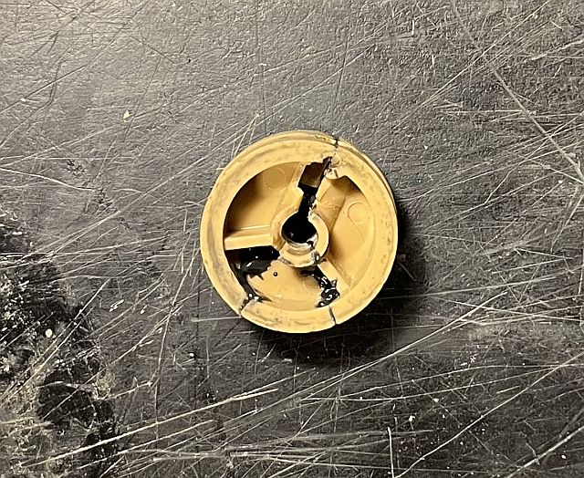
I glued the pieces of the plastic spacer with JB Weld epoxy. The reguled spacer is shown below.
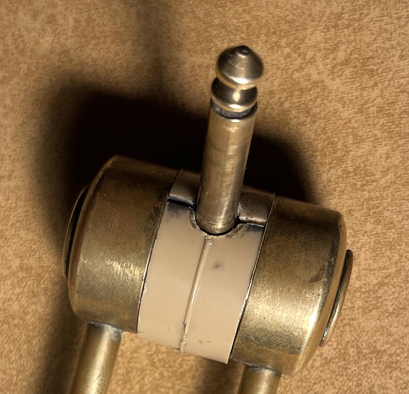
It is unclear to me how the connection from the "ring" of the phone plug originally connected to one of the antenna elements. Therefore, I fabricated a round thin brass spacer with a wire soldered on that presses against the "ring." The brass spacer mounts between the plastic spacer and the antenna element to complete the connection. I placed non-conductive hollow spacers over the "tip' shaft and inside the "ring" cylinder to make the ring more secure. This approach seems to work. The restored antenna plug is shown below. The thin brass spacer can be barely seen between the plastic spacer and the antenna element of the right.
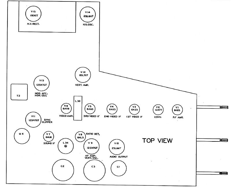
The television comprises 16 vacuum tubes. The picture below shows the tube layout.
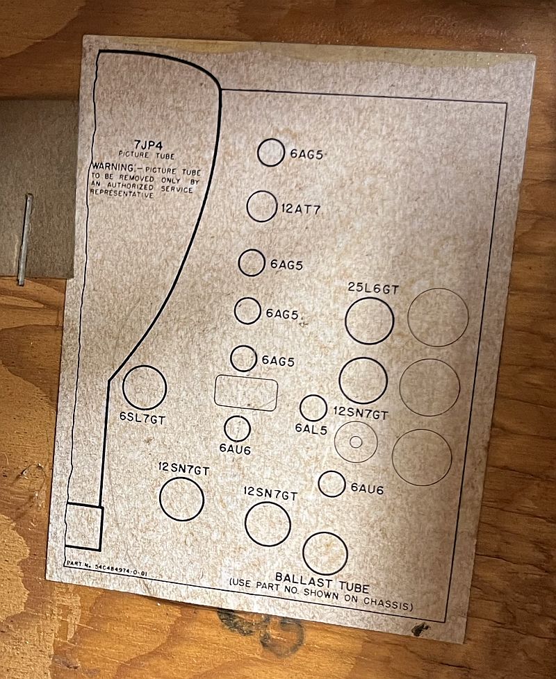
Below is a tag inside the cabinet showing the tube compliment and their locations.
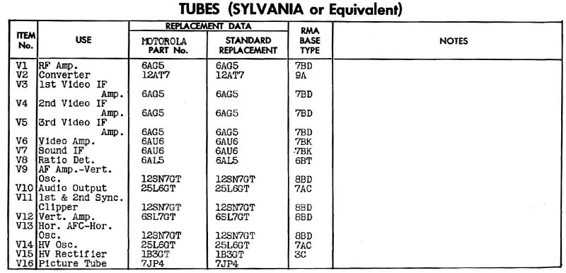
Tube Compliment
Below are other pictures of the television after cleaning it with Comet cleaner.


Click on the image below to see a video of the assembled television receiving a program (Andy Griffith).