Each amateur band has an individual calibrated dial scale. Tuning is facilitated by a rotating dial drum such that only the calibrated dial scale that is in use is visible.
The radio is a double conversion superheterodyne receiver that includes a Q-multiplier notch rejection filter, an S-meter, variable IF selectivity plus selectable SSB with a fast attack/slow release AGC circuit, a muting circuit, a heterodyne detector, and separate noise limiters for AM and SSB and CW reception.
The radio does not have an internal speaker. There is a two-screw terminal strip on the rear of the radio for connecting the wires of an external speaker.
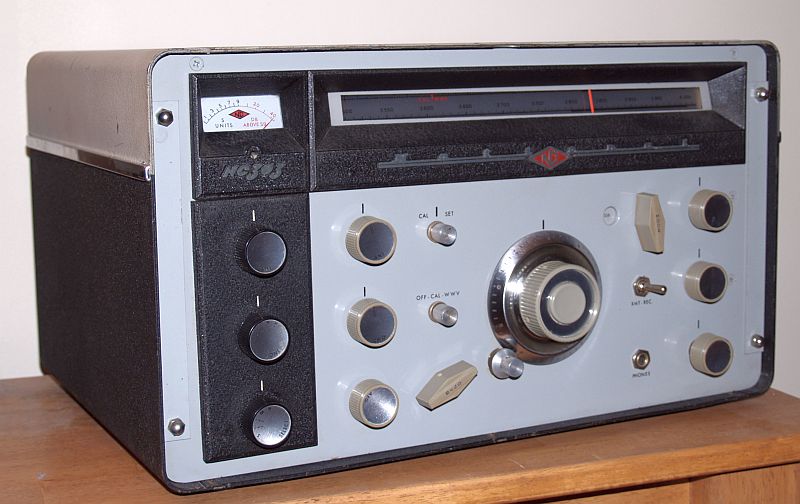
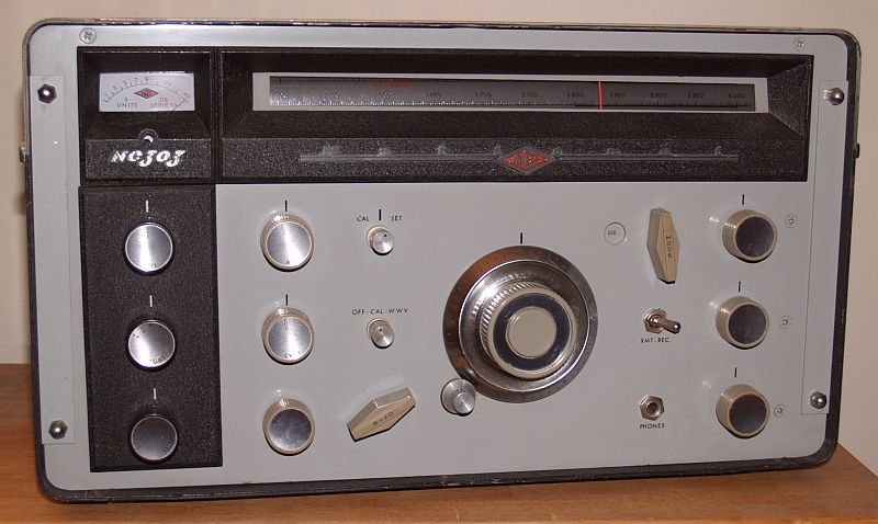
The controls on the front panel include:
| Tuning Knob and Vernier |
| AFG - Audio frequency gain control |
| RFG - RF gain control |
| TONE (HI-N-LO-PL) - Audio response switch |
| ANL - Automatic AM and manual CW-SSB noise limiters |
| MODE(ACC-AM-CW-SSB) - Operating mode |
| SELECT (S-SB1-SB2-M-B) - IF selectivity: S(400 Hz), SB1(2 kHz), SB2(2 kHz), M(3.5 kHz), B(8 kHz) |
| BAND - tuning range selector |
| CWO - Heterodyne detector oscillator tuning |
| NOTCH - Q Multiplier notch tuning |
| DEPTH - Q Multiplier notch depth control |
| ANT - Antenna trimmer |
| CAL-SET - Pointer position control |
| OFF-CAL-WWV - Crystal calibrator function switch |
| XMIT-REC - Standby-Operate switch |
The S, M, and B positions of the IF selectivity switch are centered on the 80-kHz 2nd IF frequency. The SB1 and SB2 positions of the IF selectivity switch are centered at 81.5 and 78.5 kHz, respectively. The SB1 and SB2 positions are special features of the radio that allow instantaneous on-knob selection of the correct sideband (lower or upper sideband) for SSB operation. These two positions provide optimum bandwidths of 2 kHz centered on the received sideband.
The M position of the IF selectivity switch is provided to improve the readability of phone operation when interference is heavy and the B position makes it possible to copy net stations or round table discussions with minimum retuning.
The Tone switch provides selection of optimum audio response for existing signal conditions. Provision is made to attenuate the low (LO) and high (HI) frequency portions of the audio spectrum, either individually or together (PK) or none (N).
Noise suppression in this radio is accomplished by two separate noise limiters, one for AM reception and the other for CW and SSB reception. The clipping level of the AM limier is set at the optimum level of 40-50% modulation and automatically maintains the best signal-to-noise ratio regardless of signal strength. The noise limiter for CW and SSB is a separate double-ended limiter with a manually-adjustable clipping level.
The radio incorporates an adjustable notch filter to reduce interference caused by heterodynes in the reception of phone signals. The Q multiplier provides a sharp rejection notch that can be positioned anywhere in the IF passband to reject interfering carriers.
The receiver frequency plan is a dual-conversion superheterodyne circuit with the first IF at 2,215 kHz and the second IF at 80 kHz.
The filament current of the first conversion oscillator is regulated through a current stabilizer (ballast) tube, a 4H4-C (V13). This tube is a high-failure item and is now difficult to obtain. National Company recognized the reliability issues with this tube and in the manual, suggested using a 6V6 audio output tube in place of the ballast tube as a temporary measure. The filament pins of the 6V6 are the same as the 4H4-C, so the 6V6 can be inserted in the 4H4-C tube socket with no modifications. The current rating of the 6V6 filament is suitable for the oscillator tube current draw. When I received this radio, a previous owner substituted 3 5-ohm resistors mounted in an old tube base for the 4H4-C. I prefer using the 6V6 even though it may not provide the stability of the 4H4-C tube during power line voltage fluctuations. I personally have not observed any issues with using a 6V6.
Below is the tuning range of the receiver:
| 160 Meters | 1.8 - 2.0 MHz |
| 80 Meters | 3.5 - 4.0 MHz |
| 40 Meters | 7.0 - 7.3 MHz |
| 20 Meters | 14.0 - 14.4 MHz |
| 15 Meters | 21.0 - 21.5 MHz |
| 11 Meters | 26.5 - 27.5 MHz |
| 10 Meters | 28.0 - 29.7 MHz |
| 6 Meters | 49.5 - 54.5 MHz (with converter) |
| 2 Meters | 143.5 - 148.5 MHz (with converter) |
| 1 1/4 Meters | 220.2 - 225.0 MHz (with converter) |
| WWV | 10.0 MHz (with calibrator) |
When I received this radio, it was quite dirty with mildew on all of the knobs. Pictures of the radio as received are shown below.
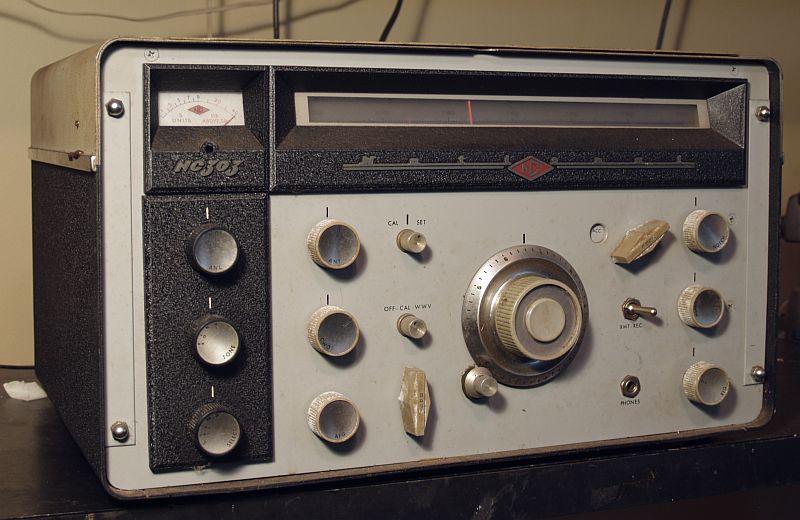
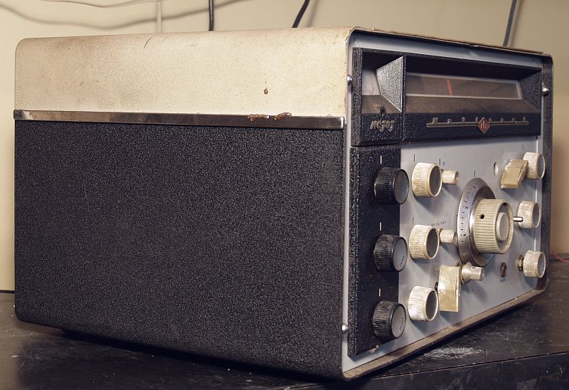
I used water with Clorox and Comet to clean all the knobs and the front of the radio. I used the same cleaners to clean the metal cabinet and I used a hose to wash the cleaners off the cabinet.
The dial and meter windows were cloudy. I used Novus #2 Fine Scratch Remover to remove e the cloudiness from the dial and meter windows.
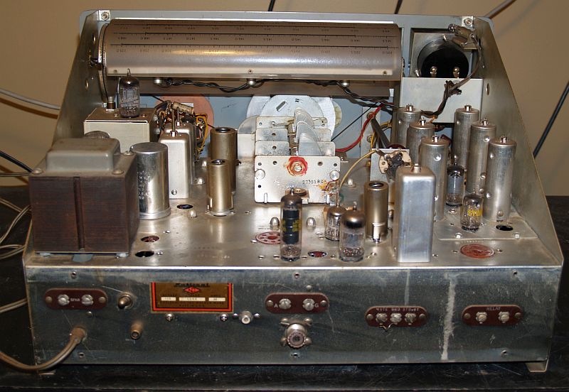
The underside of the chassis was mostly clean, but there were a few remnants of spider webs. The underside of the chassis is shown below.
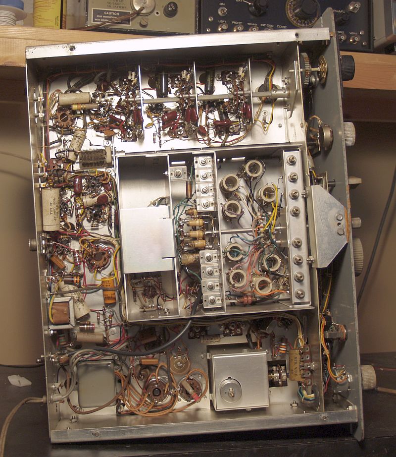
The top of the chassis did have a dirt film everywhere. I cleaned it off with a toothbrush, water, and Comet cleanser. The top of the chassis after cleaning is shown below.
The radio did not work properly when received. In addition to replacing the resistors emulating the 4H4-C ballast tube, I had the replace the 5Y3 rectifier and the 6BZ6 RF amplifier tubes to make it work. Several of the switches were corroded and I had to d-ox them. The troublesome switches included the limiter switch (most notable problem was on AM where no audio was passed),the IF selectivity switch, and the tone switch. The RF gain potentiometer was also intermittent at max gain where it is usually positioned. The S meter zero potentiometer was also intermittent at where it is usually positioned to zero the meter. De-oxing these components solved the problems.
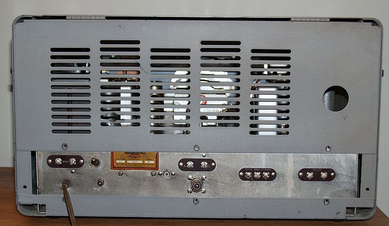
A previous owner has made some modifications to this radio. First, the radio's on/off control was originally incorporated into the RF gain control. Apparently the original RF gain control became defective and was replaced with only a 10k potentiometer without a switch. A toggle switch was incorporated into the rear of the chassis to implement the on/off function. The toggle switch can be seen in the picture immediately above.
Another modification is the addition of an external connection to the plate of the first mixer. A coaxial cable was added that runs from a phone plug added to the rear of the chassis to a small value capacitor that connects to the tube plate. This modification apparently provides a means to use an external oscilloscope to monitor a received signal. Two phono jacks can be seen in the picture above - one is original and is for injection of the signal from a converter accessory and the other is the one added.
The final modification is the addition of a UHF SO-239 coaxial jack for the antenna. The original radio has a two-screw terminal strip for antenna and ground which are still present and functional.
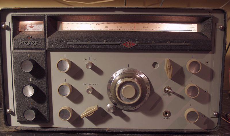
After replacing the tubes and de-oxing the switches, the radio works well and is quite sensitive. The large main tuning knob and its flywheel action is a pleasure to tune in signals. The small knob adjacent to the main tuning knob implements fine tuning by pressing it in such that a rubber washer presses against the main tuning knob. When pressed in, the small knob turns the large knob and slowly tunes the radio. One has to pull out the small knob to enable the large knob to move freely.
Below is a picture of the back of the radio.
Below is a picture of the radio operating. The center lamp in the dial drum is not operating.
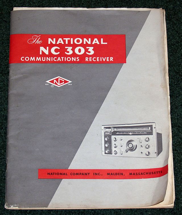
The radio also came with the original manual as shown below.
Stabilizer |
Regulator |
Converter |
Multiplier |
Noise Lim |
Noise Lim |
Diode |
Detector |
& AF Amp |
Output |
||||||