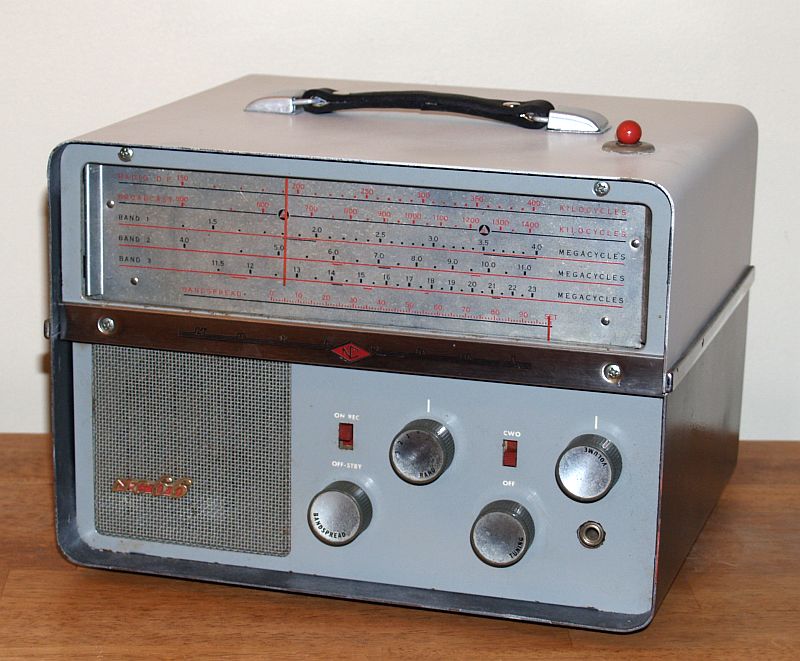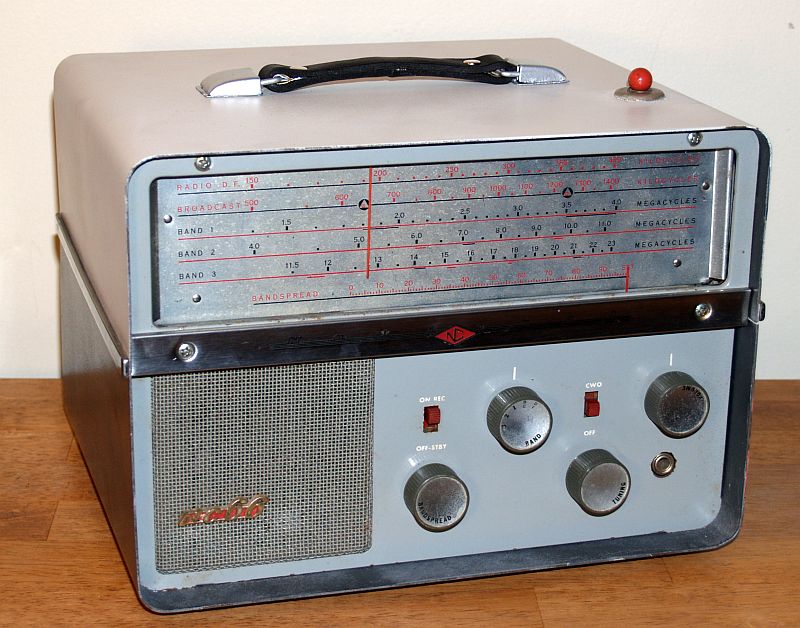
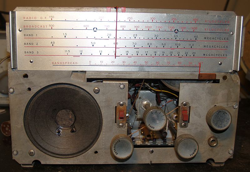
Note that the dial of the receiver has the Civil Defense Markings at 640 and 1240 kc on the AM Broadcast that identify the former CONELRAD frequencies. The amateur bands (160 - 15 meters) are underlined in black and the principal International Broadcast bands are underlined in red.
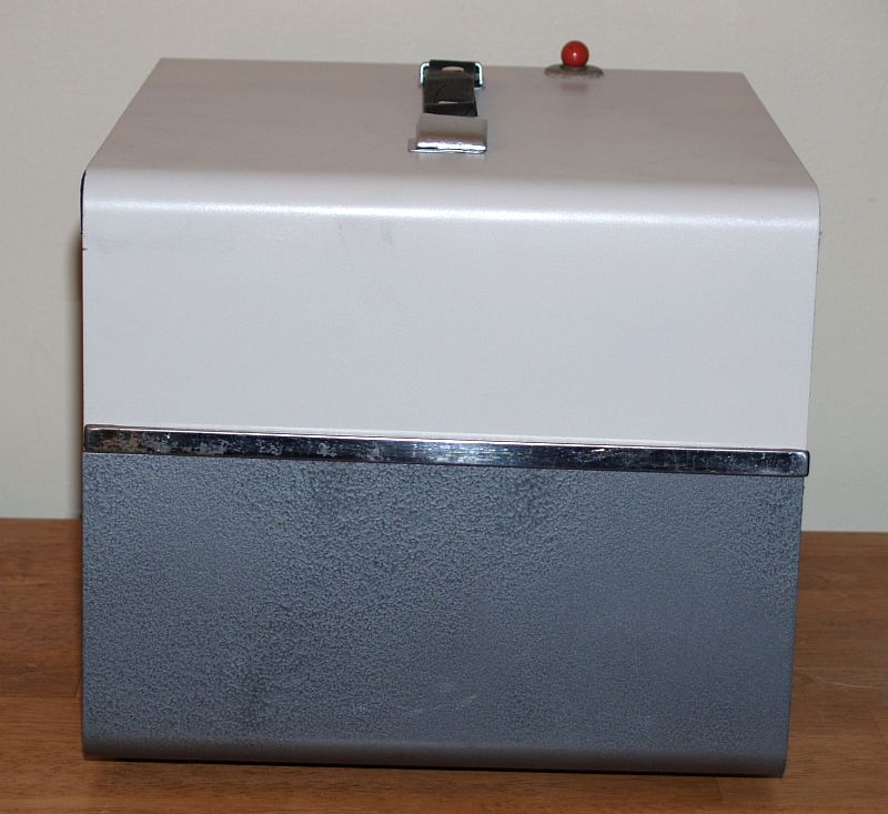
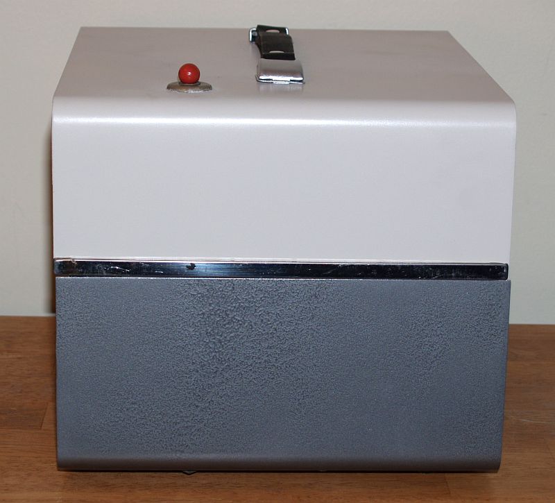
The receiver is contained in a metal cabinet finished in a two-tone neutral gray with chrome trim. The cabinet has ruber feet and a leather carrying strap. All operating controls and switches, dial scale, phone jack, and speaker grille are located on the front panel.
The receiver can be operated on 115V ac or dc, battery power, or 220 Vac. Operating on 220 Vac requires the National NC-66/VA220V adapter.
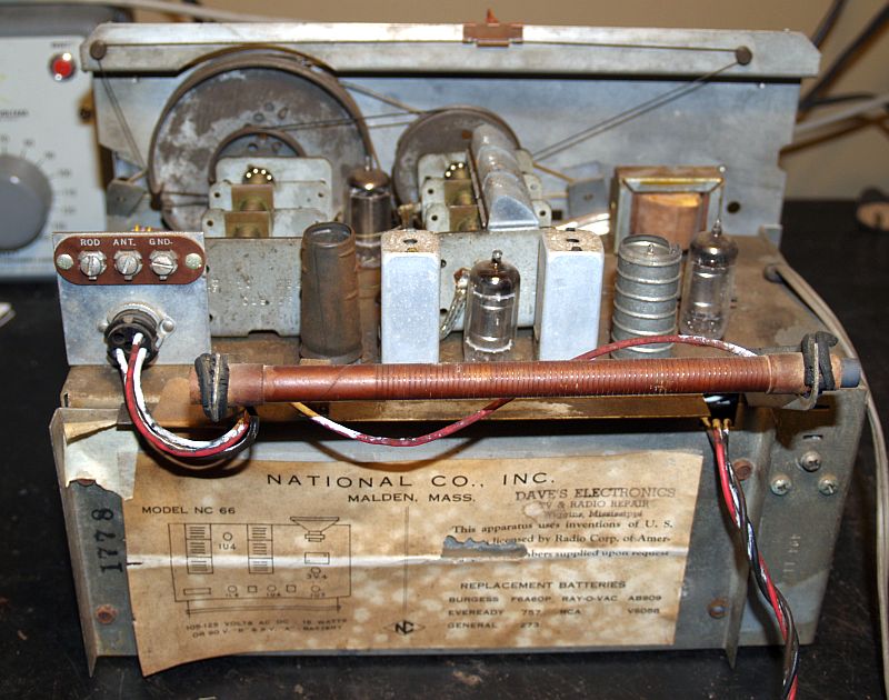
The receiver features two built-in antennas - one is a ferrite rod loop antenna for the radio directon finder and broadcast bands. the other antenna is a telescoping rod antenna for shortwave reception. An external antenna for fixed site shortwave reception may be connected to terminal provided at the rear of the chassis. The radio with the telescpoing rod antenna partially extended can be seen below.
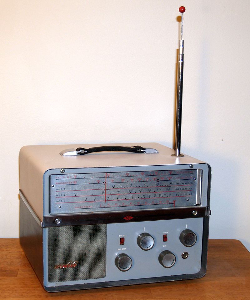
The bandswitching arrangement allows continuous tuning from 150 kc to 23 mc. The radio beacon, AM broadcast, Marine, Commercial and Police (at the time) Foreign Broadcast and 160 through 15 meter Amateur Radio bands are covered. Both general coverage and bandspread tuning are provided through 5 tuning ranges. The band coverage is:
Radio Direction Finding 150 kc to 400 kc
AM Broadcast 500 kc to 1450 kc
Band 1 1420 kc to 4045 kc
Band 2 4.0 mc to 11.4 mc
BAND 3 11.0 MC TO 23 mc
The controls on the front panel include:
| ON-REC OFF-STBY |
| CW-OFF Switch |
| TUNING |
| BANDSPREAD |
| BAND SELECT |
| VOLUME |
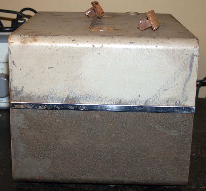
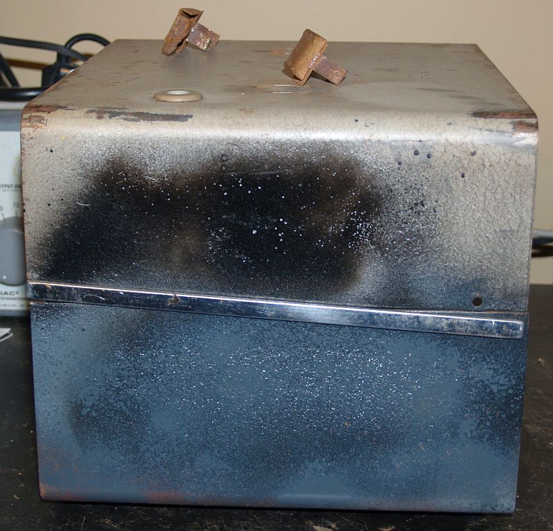
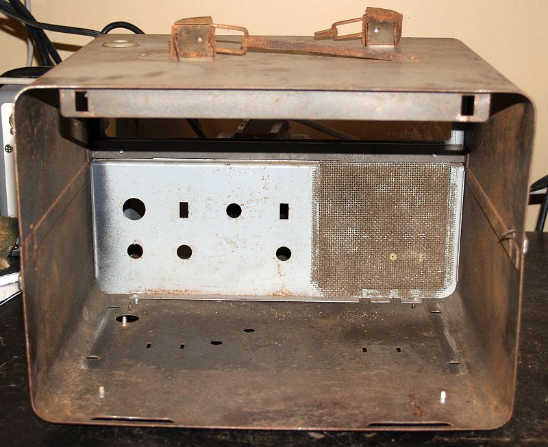
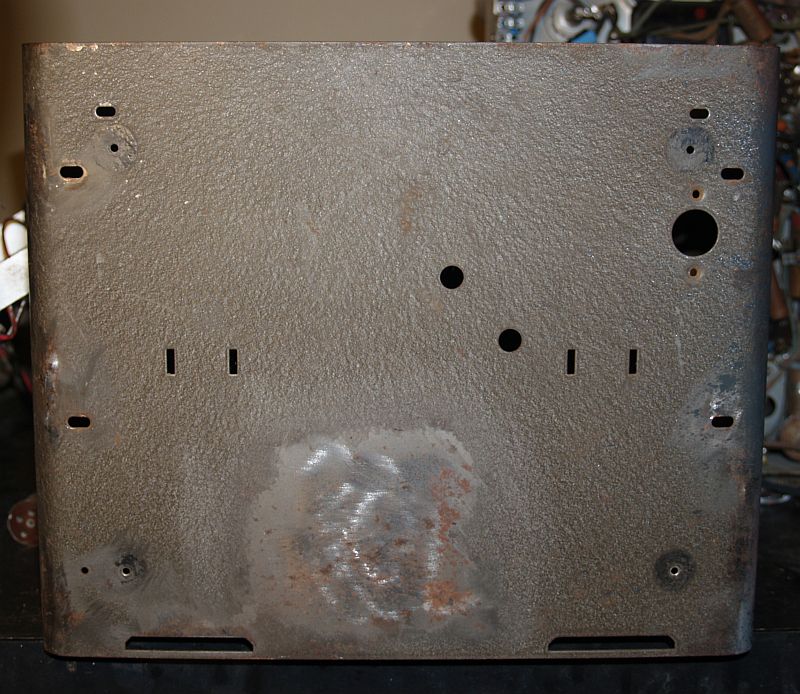
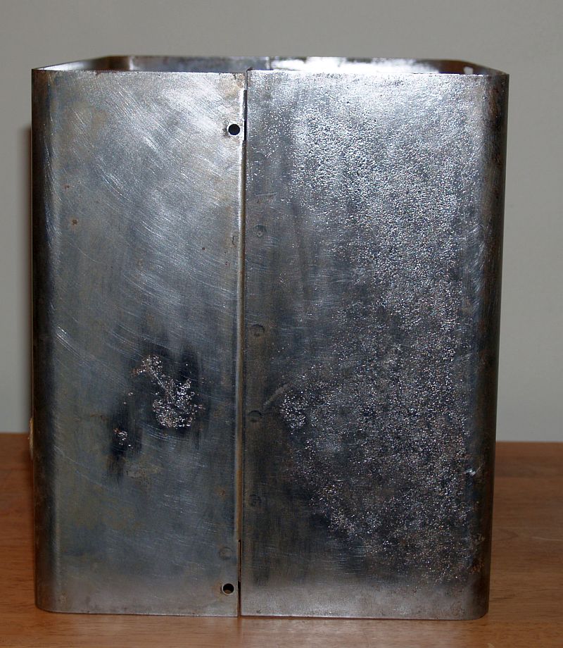
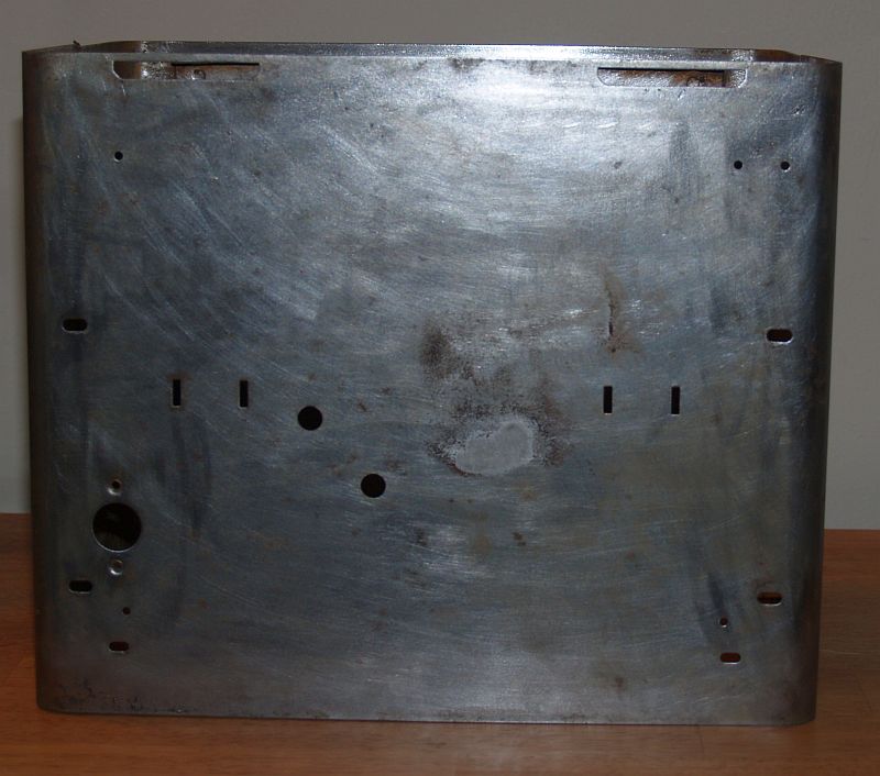
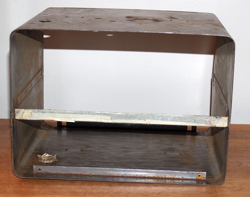
When I received this radio, the original paint was in bad shape and the steel case was pitted by rust as seen below.
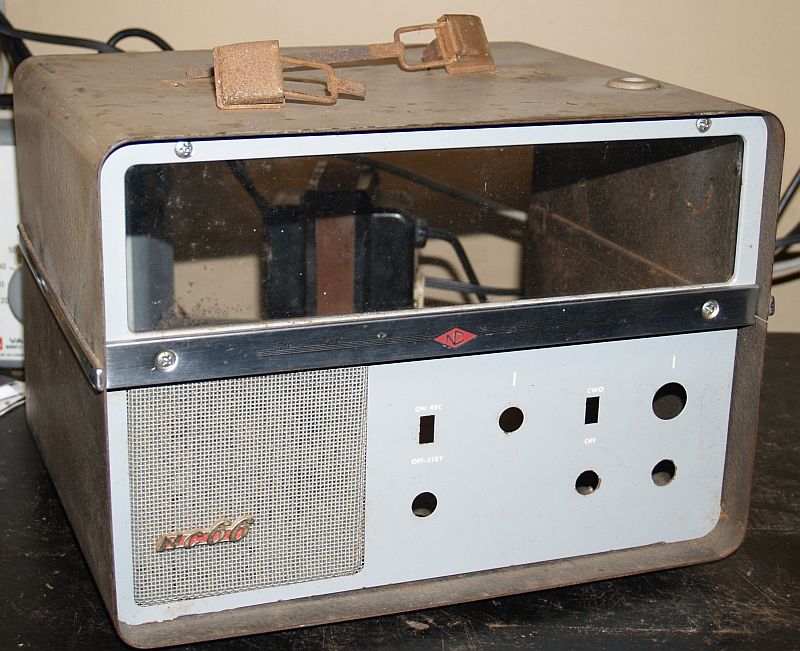
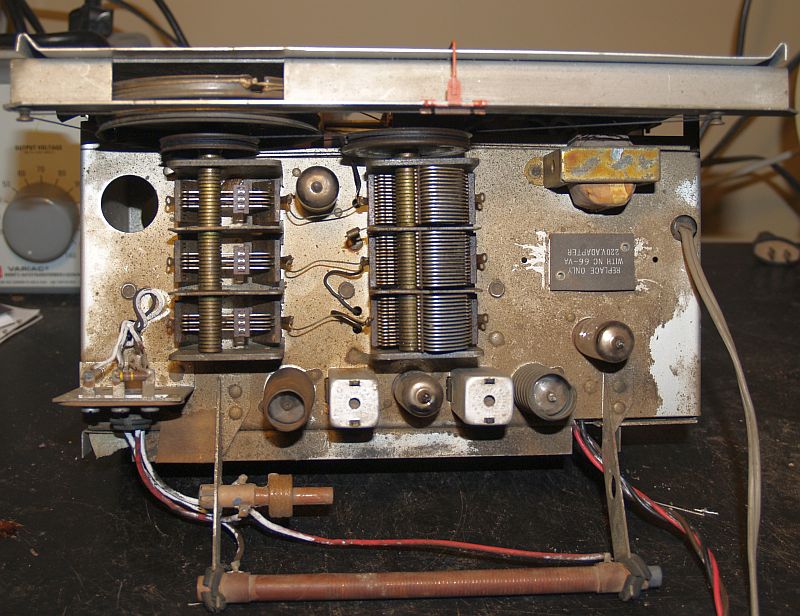
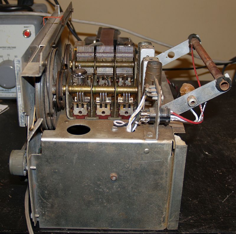
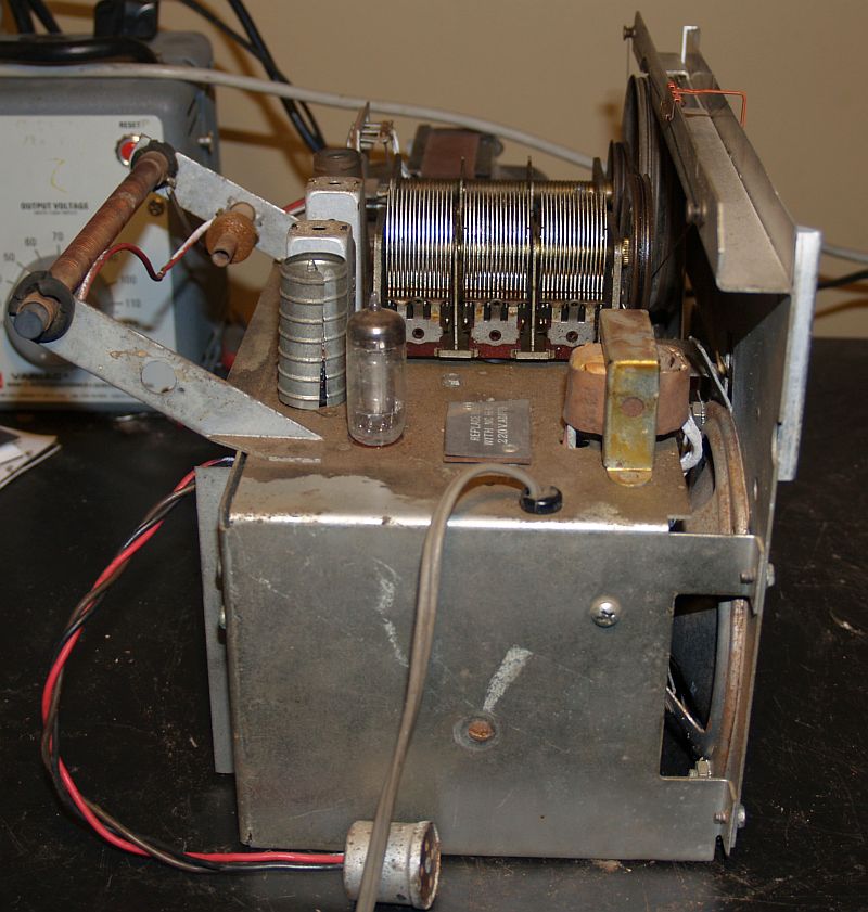
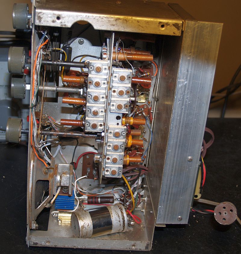
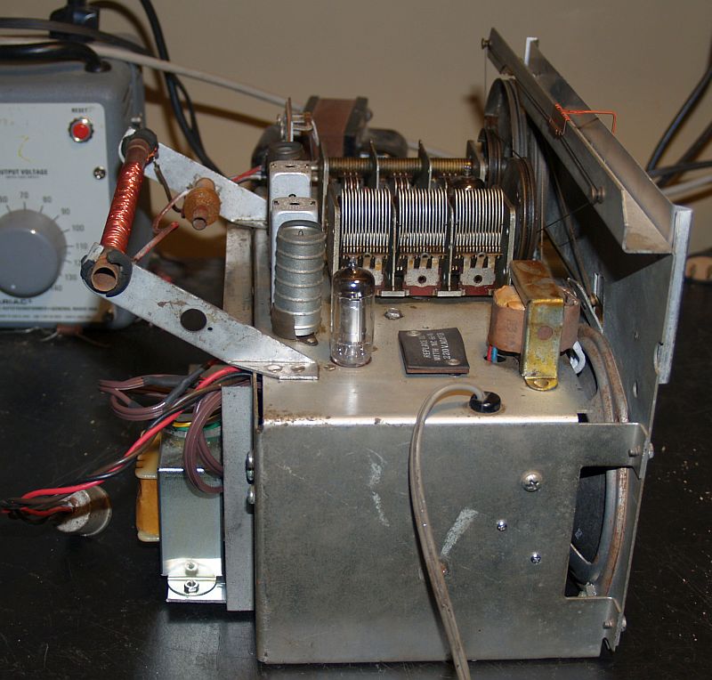
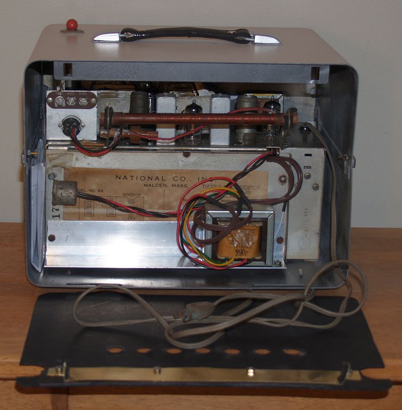
The pictures below show the chassis as received.
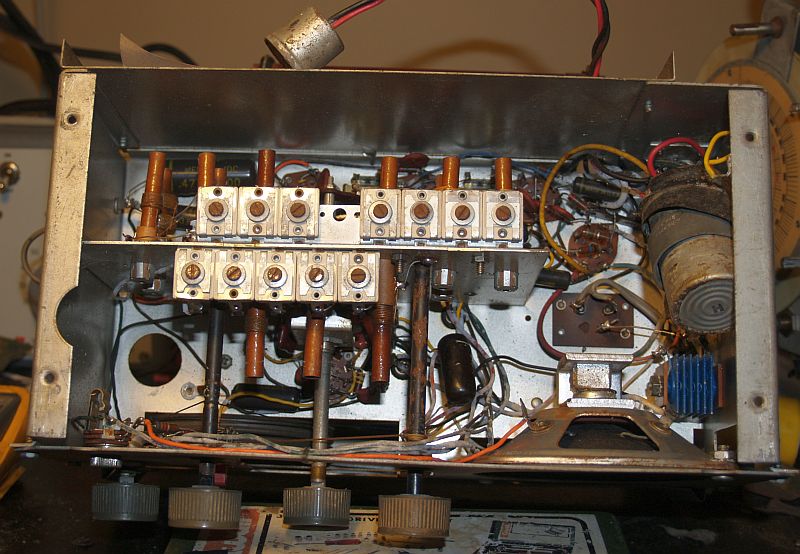
The radio did work (on 115 Vac) when I received it. Someone had removed the original selenium rectifier from the circuit and inserted a silicon diode in its place but did not account for the lower voltage drop of the silicon diode. In addition, R20 (82-ohms) was missing. I installed an 82-ohm 10W resistor in series for R20 to account for this lower voltage drop and measured about 82V on the B+.
When using ac voltage, the chassis itself is connected to one side of the ac power line, making it a "hot" chassis and is therefore unsafe. I installed an isolation transformer in series with the original power cord to prevent this unsafe condition. The isolation transformer I used is a Triad N-68X. I mounted the transformer on an aluminum right-angle bracket and mounted it on the back of the chassis using the original chassis back panel screws as shown below. The back panel is held on with 5 screws and must be removed for aligning the radio. I left wire leads to the isolation tansformer long enough to service the radio for alignment.
The multi-element power filter capacitor was originally held in place with tape as can be seen above in the photos of the as-received condition. This capacitor was good and is not original. I fabricaed an aluminum band and rigidly attached it to the chassis. This repair can be seen below along with the gold-colored 82-ohm power resistor partially hidden below.
I added a 30pf capacitor in series with the Band 2 oscillator coil to bring that band in calibration at 10 MHz.
The winding on AM Broadcast ferrite rod antenna on the rear of the chassis had several breaks in it along the length of the rod. The AM Broadcast band would still work, but its sensitivity was low. I thought about attempting to fix those breaks, but the wire is quite thin and the breaks were numerous. So, instead, I wound a new winding on top of the old as seen below.
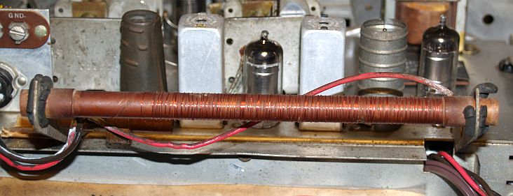
Even though the winding spacing is not uniform, the radio sensitivity on AM Boradcast is quite good now.
I cleaned the dirt and grime off the chassis as can be seen below.
I stripped the paint from the cabinet with paint remover and cleaned the rust with white vinegar. This process also took a lot of sanding with and wire brush and fine steel wool. The cleaned cabinet is shown below. You can see where the rust pitted the sides of the steel cabinet in some of the pictures below.
I filled the rust pittings with Bondo Stage 3 glazing and spot putty (it is a red color when applied). This process required several applications with sanding in between applications.
After the spot putty applications, I painted the cabinet with RUST-OLEUM self etching primer. This process required a few applications. Then I applied RUST-OLEUM filler and sandable primer. After masking the exterior of the cabinet, I painted the inside with RUST-OLEUM gray hammered paint - this produces a "hammrtone" finish. Then, I masked off the inside and masked off the upper half of the exterior and painted the lower half and bottom with the RUST-OLEUM gray hammered paint. When dry, I masked off the lower half and bottom of the exterior and painted the top with RUST-OLEUM smokey beige satin. The result is shown below on the two sides.
The leather handle on top was missing but the handle mounts were still there but quite rusty as seen above in the picture below.
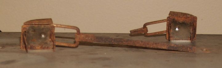
I cleaned these mounts using the same process as the cabinet. I primed them using the same process. I painted the mounts using RUST-OLEUM silver paint. I do not have the ability to chrome plate them.
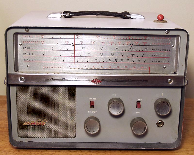
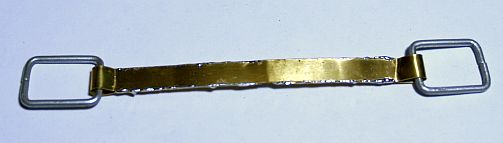
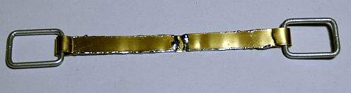
The original handle was made by placing leather over a steel strap. The steel strap is required becasue the radio is so heavy (approximately 16 lbs less batteries). I fashioned the metal strap using 0.15 in thich brass as shown below.
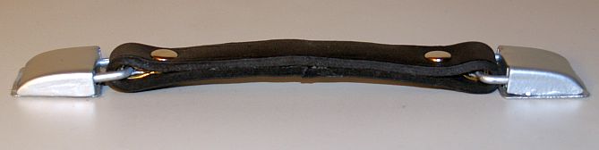
I wrapped a Tofl ľ-inch wide black leather strap over the metal strap and made the ends meet in the center of the underside. I placed a medium rapid rivet on each end through the two layers of the leather stap and through the brass metal strap. I glued the open edges of the leather with contact cement so that the brass strap could not be seen from an edgewise view.The completed handle mounted on the radio is shown below.
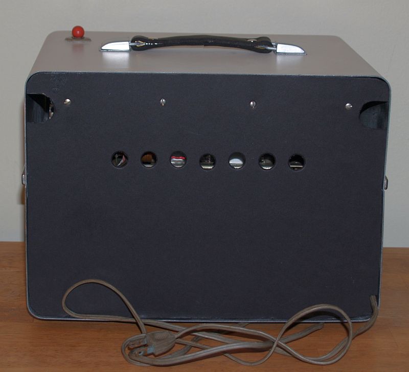
The original paperboard rear cover was missing, so I made a new one from black posterboard. Without having personal knowledge of the original rear cover, but from a picture of the rear of the radio with its original rear cover found online, I made the cutouts a close as possible (except I omitted two row of ciruclar holes). The radio with its new rear cover is shown below. Unlike the original, I included an opening in the rear cover for the power cord to exit the radio. I guess originally, when operating on mains ac power, one could not have the rear cover in place.
Using the description of the rear cover removal from the manual found online, I fabricated a brass "latch" that I believe functions similar to the original. The brass latch can be seen in the picure below.
The radio sold for $129.95 in 1957 as seen in an advertisement in Boys Life magazine in June 1957 as shown below.
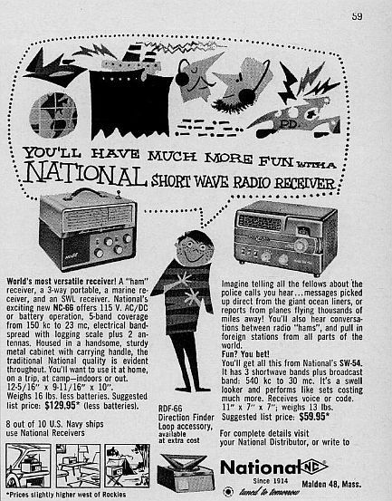
I do not have the National RDF-66 Direction Finder accessory mentioned in the advertisement. That accessory is a passive device that includes a rotatable rod antenna for the radio beacon and AM Broadcast bands and a signal strength meter. It plugs into the rear of the chassis. One unplugs the radio's AM Broadcast and radio beacon rod antennas and plugs in the direction finder in its place. The radio's AGC voltage is run through this plug to the direction finder meter. The direction finder will sit on top of the radio. The direction finder has a cutout on the bottom to accommodate the handle.
The radio plays well and is quite sensitive on the AM Broadcast and shortwave bands.
Click on the image below to hear the radio receiving and playing a tune on WSM in Nashville, TN as received in Huntsville, AL.