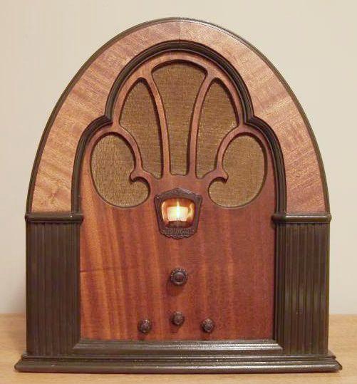
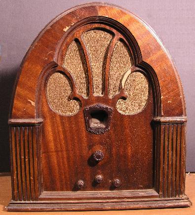
This radio is the "classic" cathedral style designed by Edward Combs and is highly sought after. The arch of the radio is made of mahogany. This radio has several Philco tubes that could be original to the set. Two of the tubes are the old style "globe" type - the other tubes are of the shoulder type. This radio plays clearly and loudly with no hum.
This radio is the earlier version of the Model 70. The volume control in this version is a 2-section ganged potentiometer. One section controls the bias to the cathodes of the number 24 RF amp and the number 24 IF amp. The other section is in series with the antenna and controls the RF signal amplitude applied to the radio. There is no automatic gain control (AGC) so the audio amplitude will vary with signal strength. In addition, static will sometimes overwhelm the radio signal. Switching the two-position tone control to cut the treble, will reduce the effects of static crashes. However, the radio is quite sensitive and with an outside antenna, it easily receives WSM in Nashville, 100 miles north of Huntsville.
The only problem I encountered with this radio when received was the 0.01 uF coupling capacitor to the grid of the audio output tube. The original capacitor was low in value therefore limiting the volume to a very low level. Just adding another capacitor in parallel solved this problem.
Below is a picture of the radio as I received it before I refinished the cabinet. You can see the missing veneer in the arch and on one of the strips over the speaker.
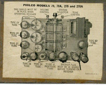
Below is a picture of a label on the tube shield that cannot be seen unless the shield or chassis is removed. It shows the tube lineup and the function of the front controls.
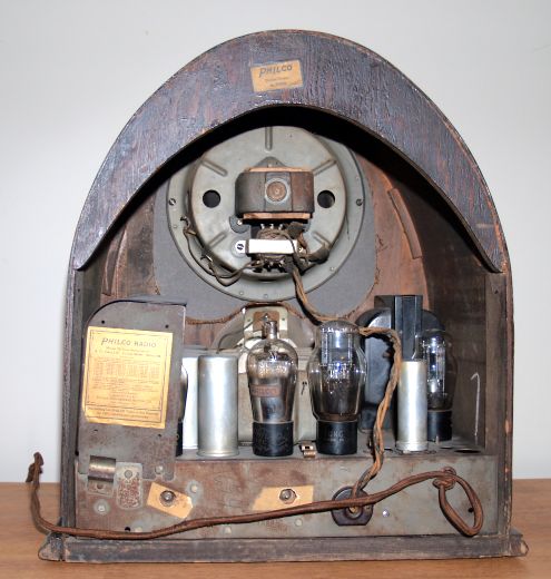
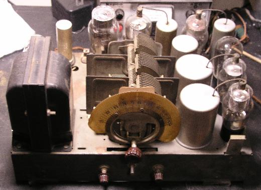
Below is a picture of the chassis (without the tube shield) after I cleaned the dust, grime, and dirt off. There was not a lot of grime, but over the years, there was a large build-up of brown-yellow grime on the tubes and IF cans. A damp rag was used to remove the grime.
Below is a front view of the chassis after cleaning. The dial scale is supposed to go through the rectangular slot in the chassis as the dial is turned. Unfortunately the dial rubs against the sides of the slot and had scratched the dial, but did not rub the numbers off. One reason for this was that the rubber grommets stabilizing the tuning capacitor were deteriorated. I stabilized it using a wedge of wood. I glued felt around the rectangular slot - the dial now slightly rubs on the felt and no scratching is experienced.
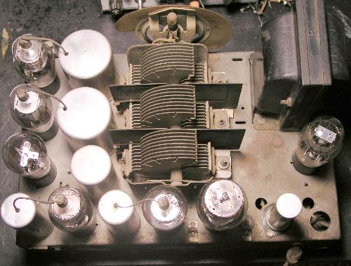
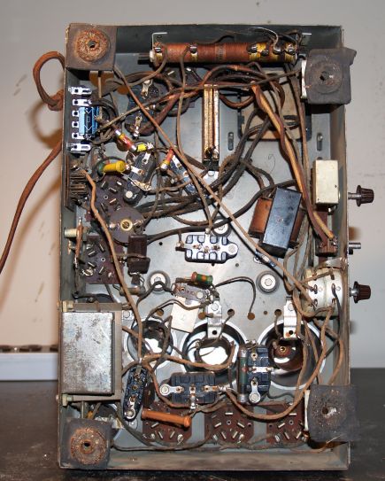
Below is a picture of the bottom of the chassis. As you can see, minimal repairs have been made to this radio. It is virtually vintage in most all parts. The output transformer mounted on the speaker is not original. Someone had replaced it long ago.
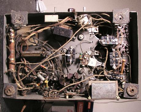
After refinishing, I reassembled the radio and was listening to it and after about 30 minutes, I heard a sizzling/frying sound. As it turned out, the electrolytic filter capacitor that someone had replaced long ago was shorting out and its wax electrolyte was melting and running out. I quickly turned it off and waited for the capacitor to cool. Then I replaced the capacitor with new ones. My repair is shown in the picture below. The new capacitors are the blue ones in the upper left. The radio works well now.
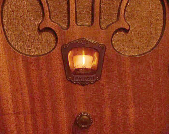
Below is a picture of the peephole dial with the radio on. I have it tuned to 650 kHz which is WSM in Nashville, TN.