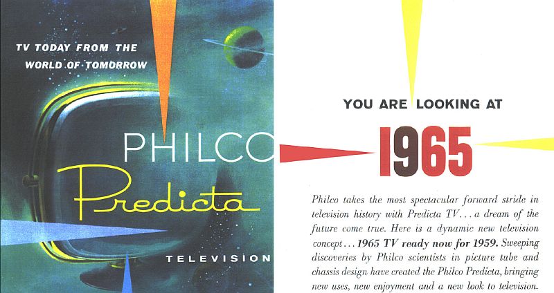
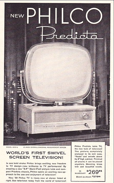
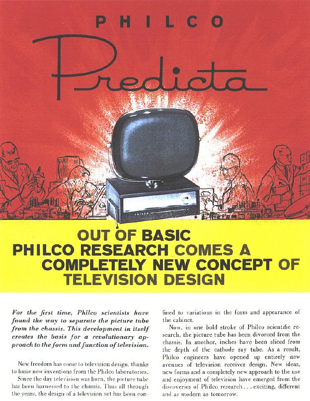
Philco's Predicta models are possibly the most distinctive televisions ever designed and caused quite a stir in the market place when they were first introduced. Philco promoted this iconic television as the "TV of Tomorrow" as stated in the 1959 advertisement below.

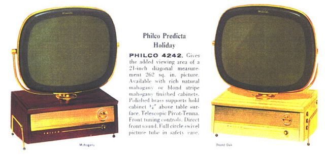
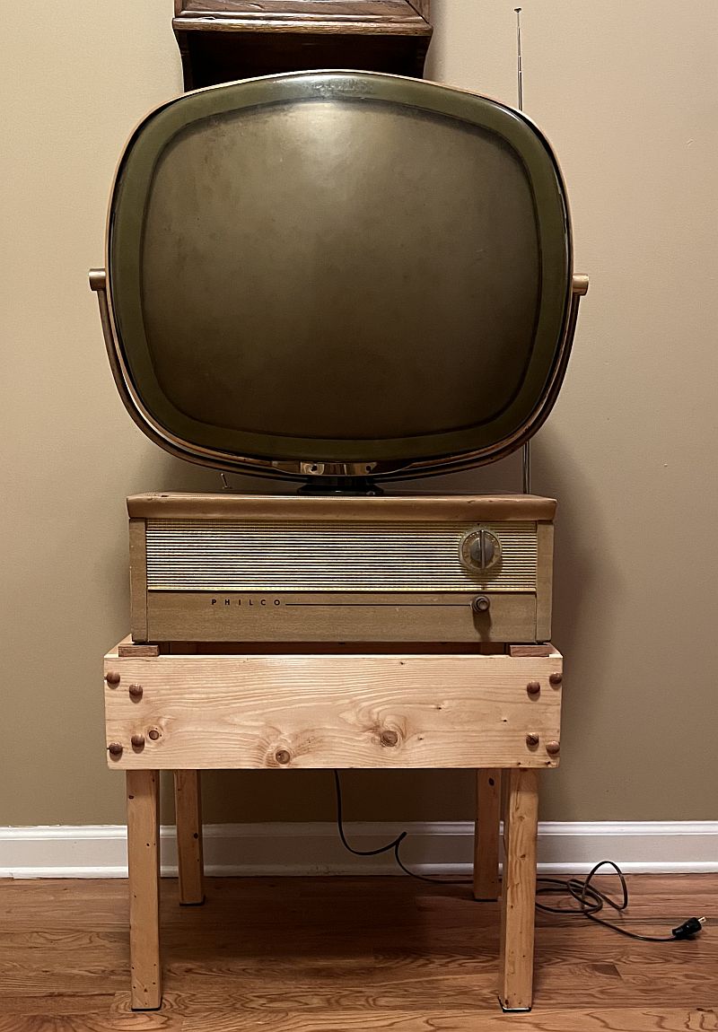
The picture tube is completely enclosed in its own case and "floats" and swivels above its eight-inch high cabinet. The Predicta was a forward-looking design that was way ahead of the competition at the time. A new plastic called "Tenite" protected the picture tube and created the tube's greenish hue, adding to the television's unusual appearance. Even today, the design is unique and quickly recognizble. Philco sold a lot of these type televisions under several different models and configurations and as such, they are not particualrly rare. The Holiday model came with a metal wire stand that I do not have. The stand raises the television off the surface to promote air flow through the television. There are screen vents on the top and bottom of the television for air flow.
The above "Holiday" model is Philco's Predicta line "entry model" but mine is somewhat rare in that it has a US UHF tuner for channels 14 through 83 in addition to the standard US VHF tuner for channels 2 through 13. The television electronic chassis is housed in a blonde wooden cabinet. The television comprises 17 vacuum tubes. All vacuum tube filaments, including the CRT filament, are in series. If the filament of one tube opens (burns out), then none of the filaments of the other vaccum tubes will illuminate. The CRT uses electromagnetic deflection with a yoke. The television is rated at 185 Watts (stamped on the rear cover but SAMS Photofact indicates 160 Watts) at 117 VAC. The video IF is 45.75 MHz and the sound is 41.25 MHz. The sound uses "intercarrier" IF processing.
The dimensions of the television are:
19 7/8 inches wide at the bottom
26 inches high from the bottom to the top of the CRT
8 inches is the height of the cabinet below the CRT
14 inches deep
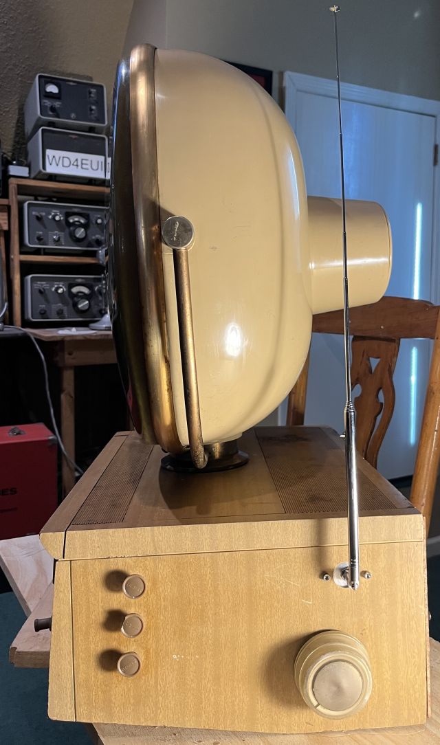
The television is unique in that the CRT is external to the cabinet. It sits on top of the cabinet on a pedestal such that it can be horizontaly rotated for best viewing.
Below is a picture of the television when I received it.
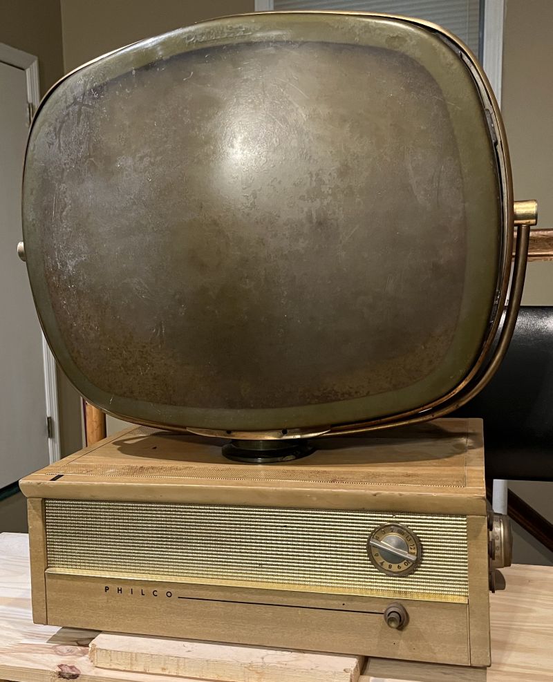
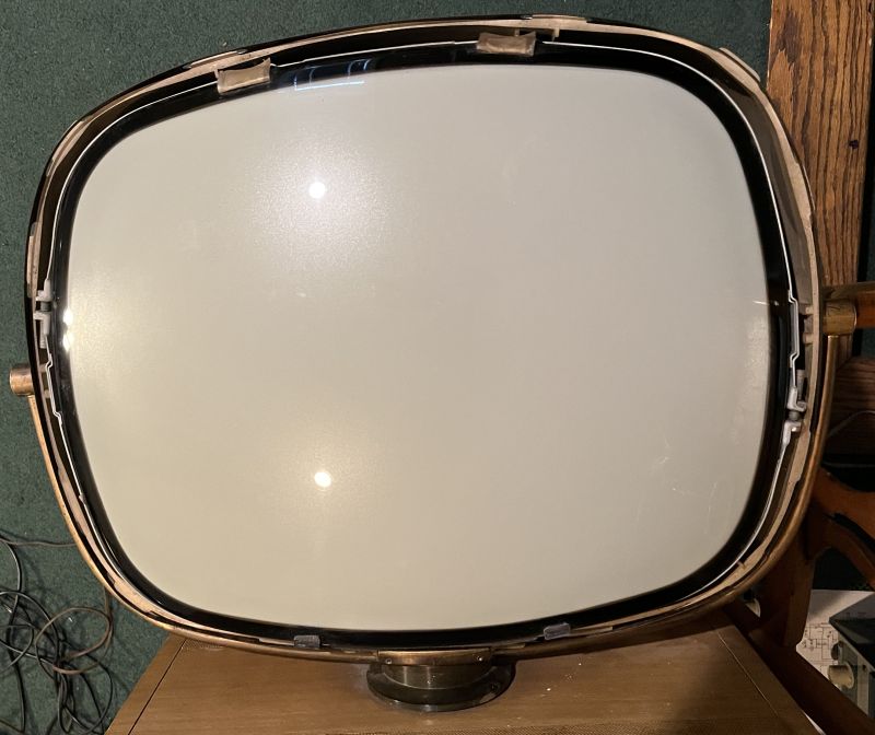
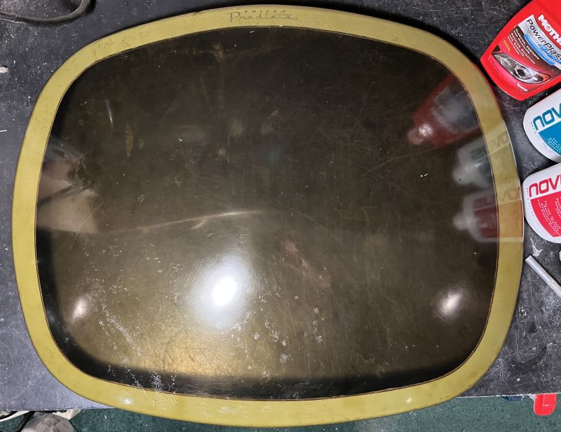
The television is in relatively good shape. The wooden cabinet has some discoloration and the metal screen vent on top has some discoloration and rust due to heat. However the most noticable defect is the cover over the CRT picure tube that has turned somewhat opaque and pitted. The CRT covers on the 21-inch Predicta televisions are prone to material degradation. This example developed a waxy, chalky buildup on both sides and has a bad smell (buteric acid). The cover is made from "Tenite," a brand of cellulosic thermoplastic materials produced by the Eastman Chemical Company. The green tint is normal, but the pitting and buildup of opaque material is a result of the material degrading over time.
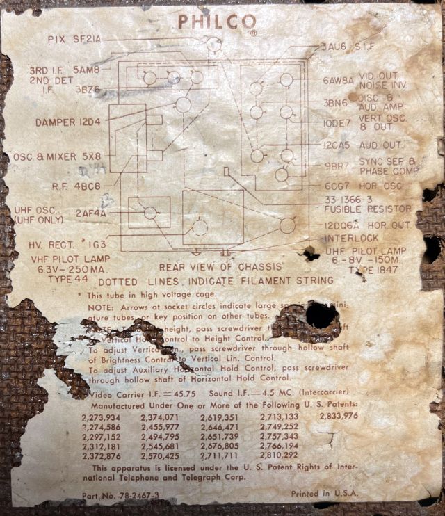
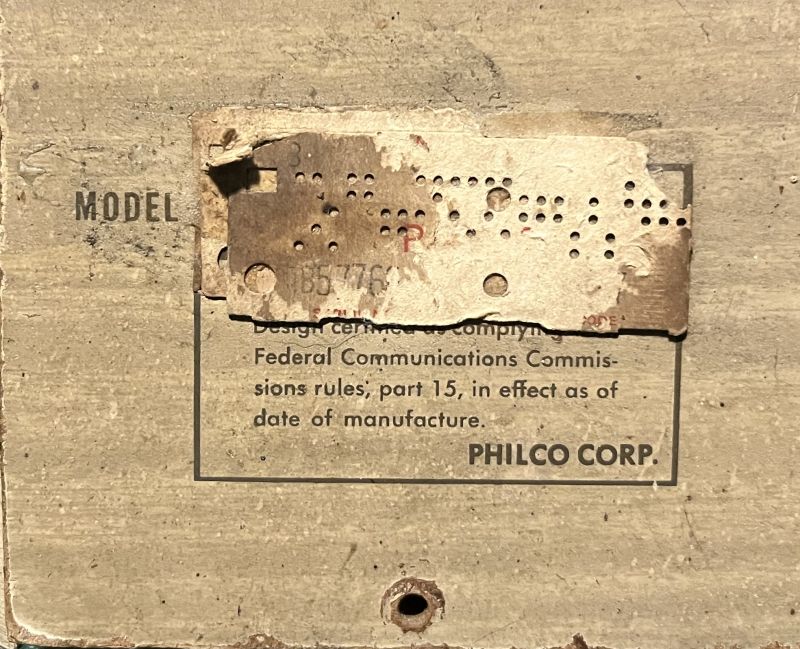
Below is a picture of the model and tube layout tag inside the back cover.
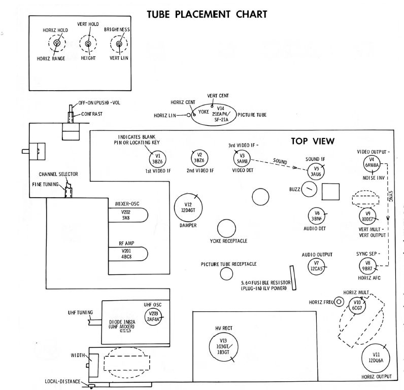
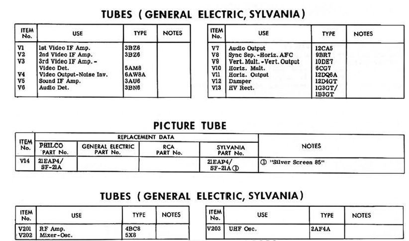
Below is the television tube placement chart from SAMS Photofact.
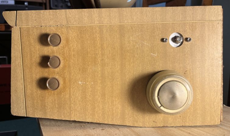
The controls on the front panel include:
| Volume Control & On-Off Switch |
| Contrast Control |
The controls on the right-hand side (facing the TV) include:
| Brightness (top) |
| Vertical Hold (center) | Horizontal Hold (botom) | UHF Tuning |
These controls are shown below:
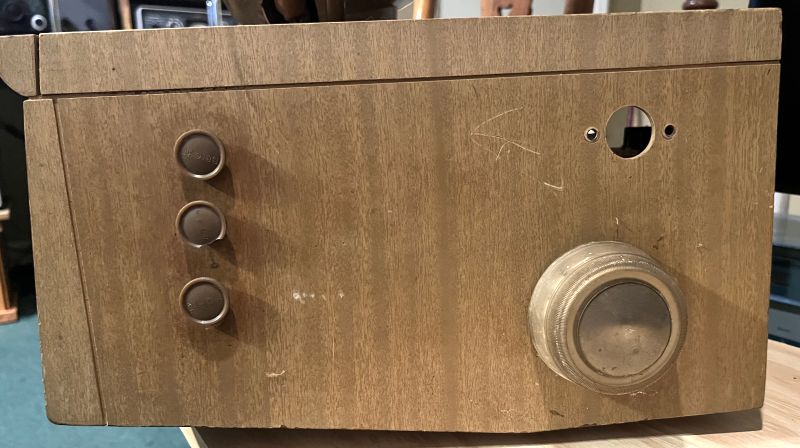
The large hole and two adjacent small holes are for the telescoping antenna that is often broken as is the case in this example. When the knobs for Brightness, Vertical Hold, and Horizontal Hold are removed, recessed controls for vertical linearity, vertical height, and horizontal range can be access using a screwdriver.
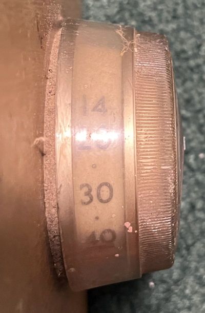
The UHF dial, shown below is continuous tuning from Channel 14 to Chnnel 83 as compared to the VHF click-stop tuning dial.
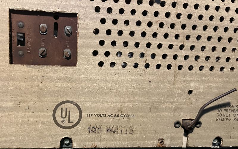
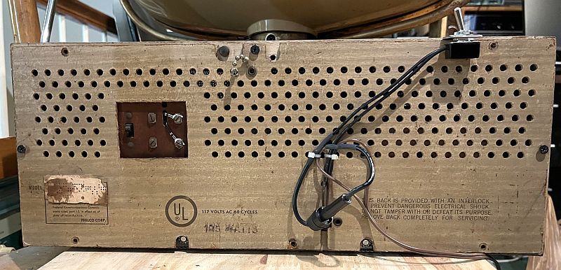
Below is a picture of the antenna and power connections on the rear of the cabinet. There are two separate 300-ohm antenna connections - one for VHF and one for UHF. There is also a local and distance receiver sensitivity switch. The power cord has been cut. I was told by the owner that his grandfather cut the cord when he retired the televison to prevent possible injuries from an television that would be unused.
Below is a picture of the model number tag on the rear cabinet cover. The actual model number is not discernable on the tag.
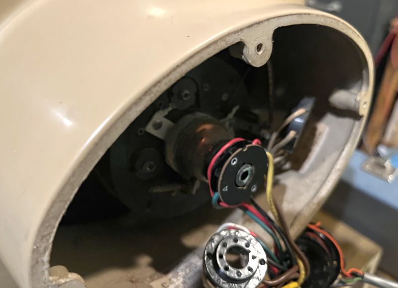
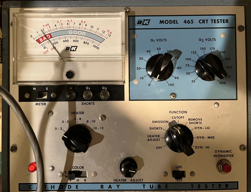
The 21-inch picture tube (CRT) is known to be a high-failure item. As such, I did not proceed with the restoration until I checked out its health. Below is a picture of the picture tube filament on being powered with my CRT tester.
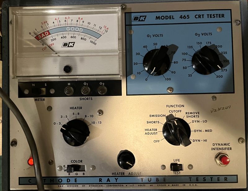
When I powered on the CRT, its emissions measured low and the CRT registered bad as shown below. This indication suggests it would not be worth proceeding with the the restoration.
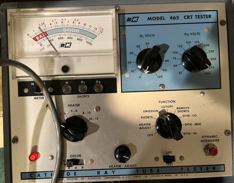
However, after leaving the CRT powered for several hours, the emissions improved as shown below:
After leaving the CRT powered for several more hours, the emissions futher improved as shown below:
The CRT emissions did not improve significantly after that above. However, I decided to proceed with the restoration and see what a actual image would look like. I did not try to rejuvinate the CRT for fear of damaging it. I was told by the owner the television worked when it was retired. As such, I thought the CRT might still be good despite the low emission reading.
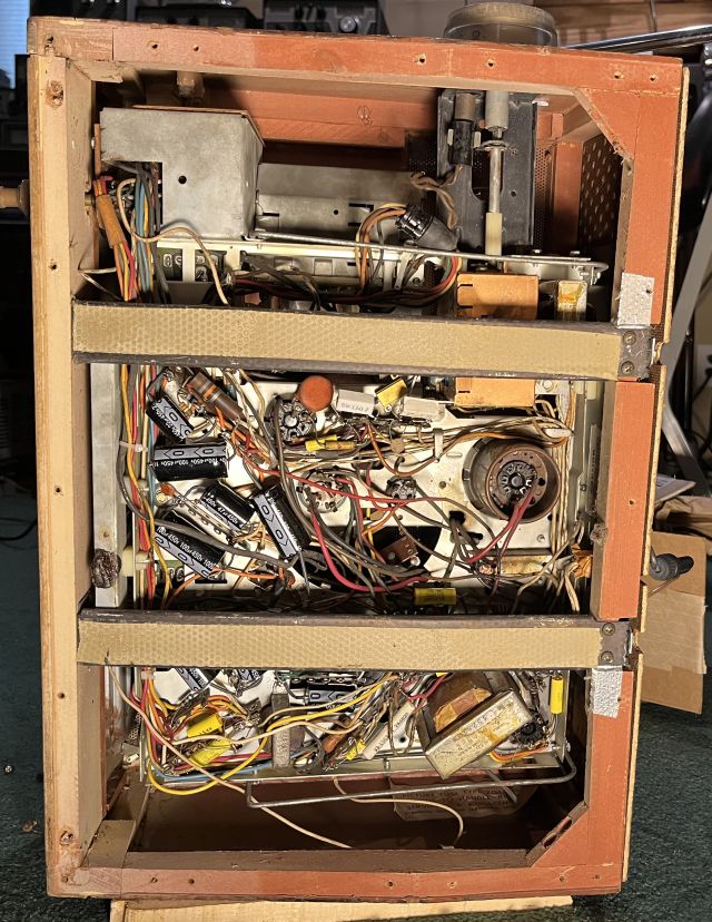
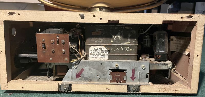
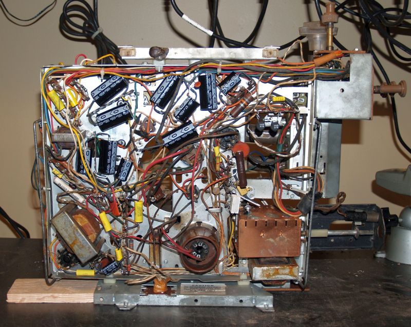
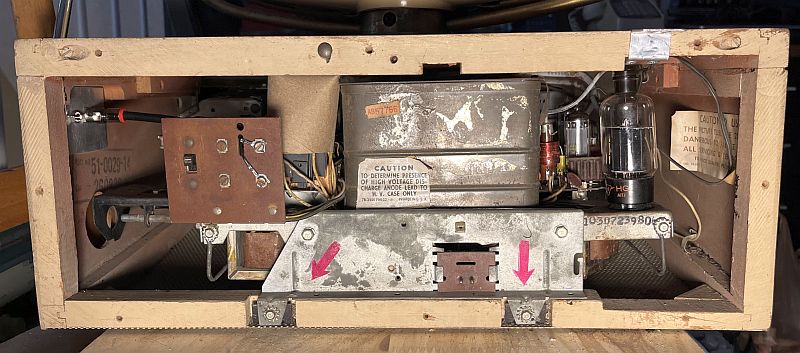
Below is a picture of the chassis inside the cabinet with the cabinet rear cover removed. Only two screws indicated by two red arrows (original OEM) hold the chassis in place.
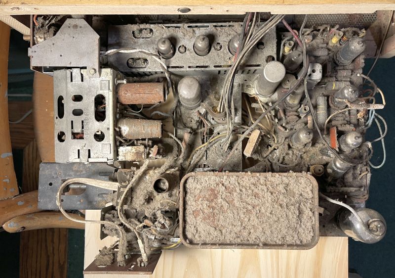
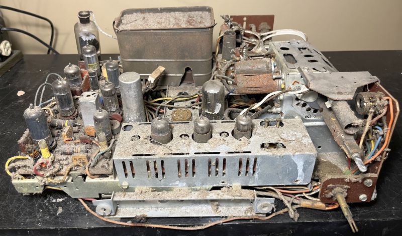
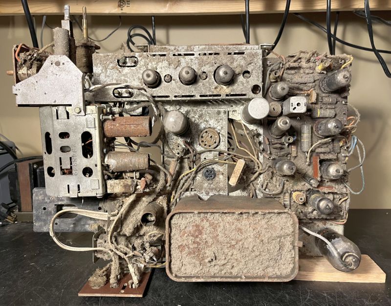
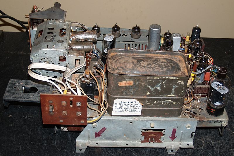
Below is a picture of the chassis after pulling it out of the cabinet. Note how dusty it was.
To completely remove the chassis, Two multi-pin plugs in the center of the chassis that connect the chassis to the CRT must be unplugged, two wires connecting to the speaker must be disconnected from the circuit board, one wire carying the video from the circuit board to the CRT must be disconnected, and the high voltage lead carrying the 15-kV CRT anode voltage must be unplugged inside the high voltage cage.
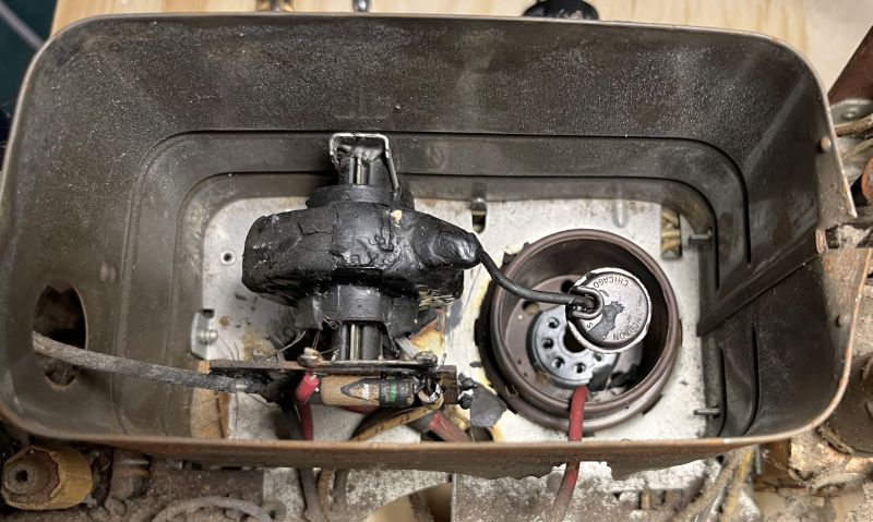
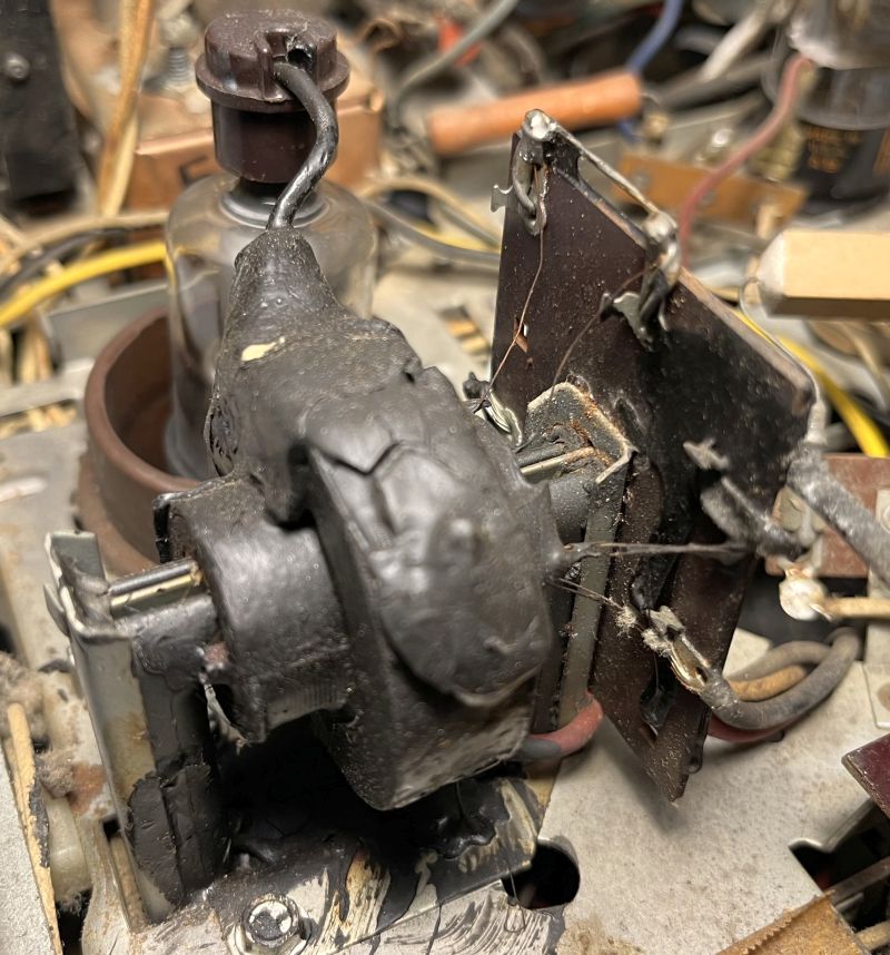
To disconnect the high-voltage lead, the high-voltage rectifier tube must be removed. The picture below shows the inside of the high-voltage cage. The red wire is the high-voltage lead.
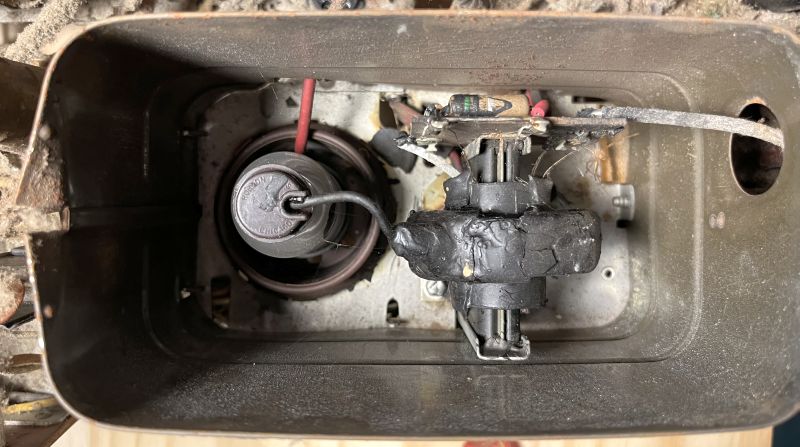
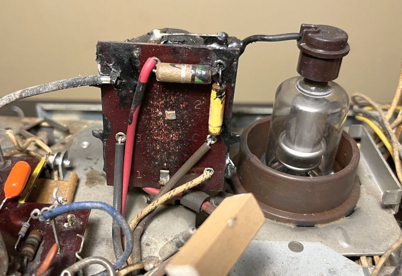
The picture below shows the high-voltage cage with the rectifier tube removed. You can see the red high-voltage lead plugs into a socket next to the tube socket.
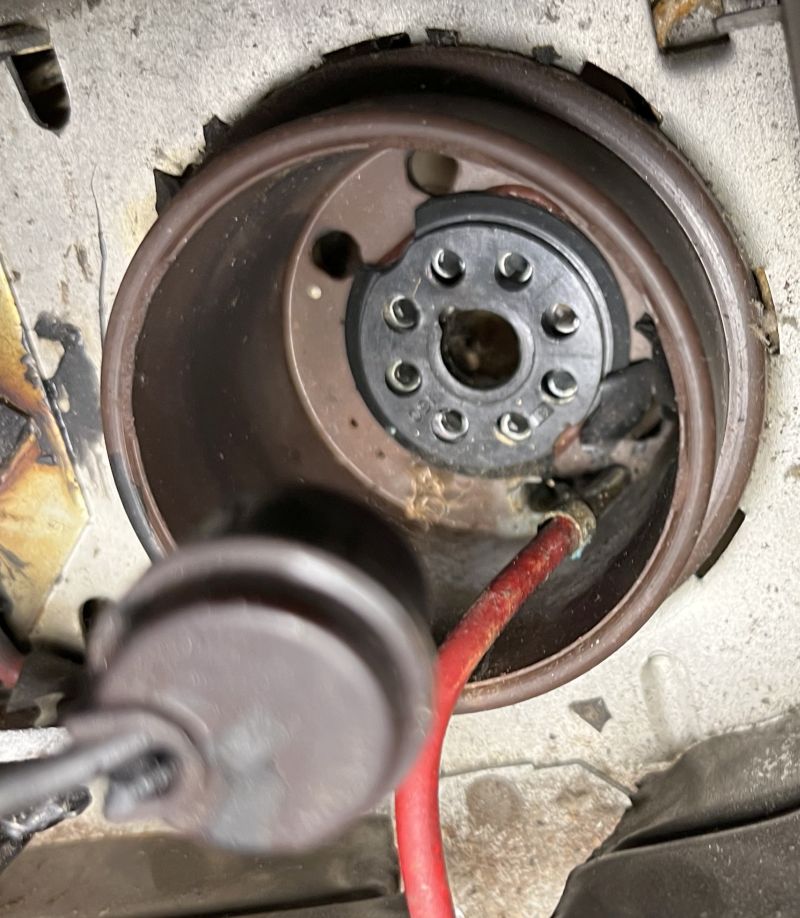
To disconnect the high-voltage lead, long needle-nose pliers are required to reach down to grab the lead end. It requires some pulling as the connection is quite tight. Below is a picture of the lead disconnected. You can see the lead end and its socket.
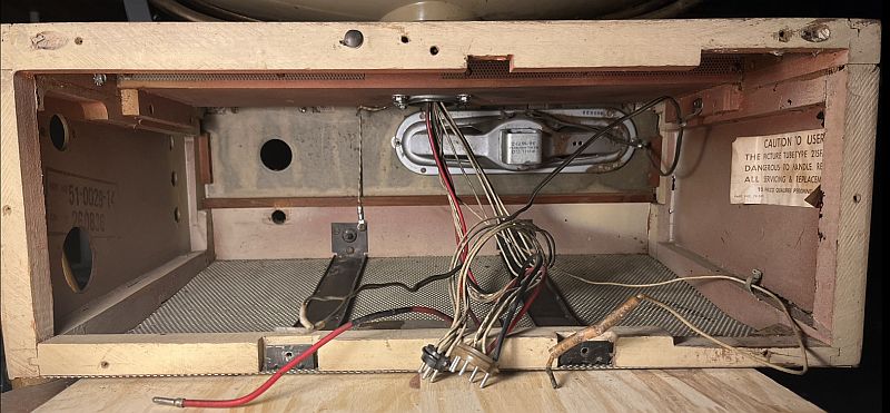
The picture below shows the inside of the cabinet after cleaning with the chassis removed. You can see the long narrow speaker mounted to the front of the cabinet.
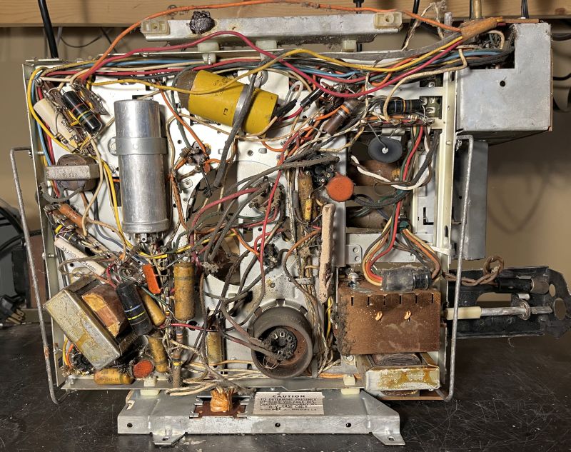
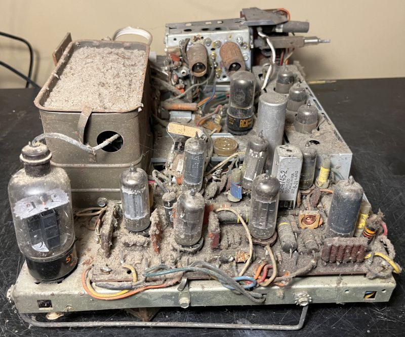
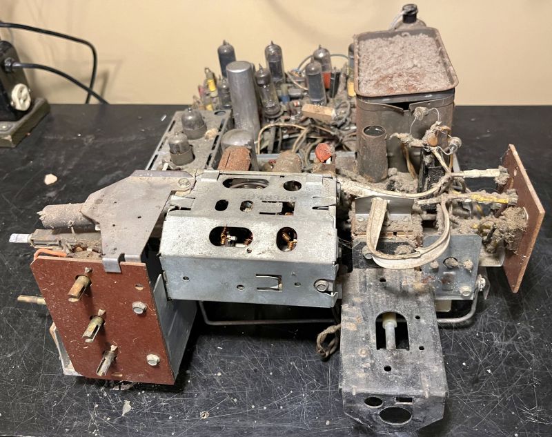
Below are pictures of the chassis before restoration when removed from the cabinet. Note how dusty the chassis is.
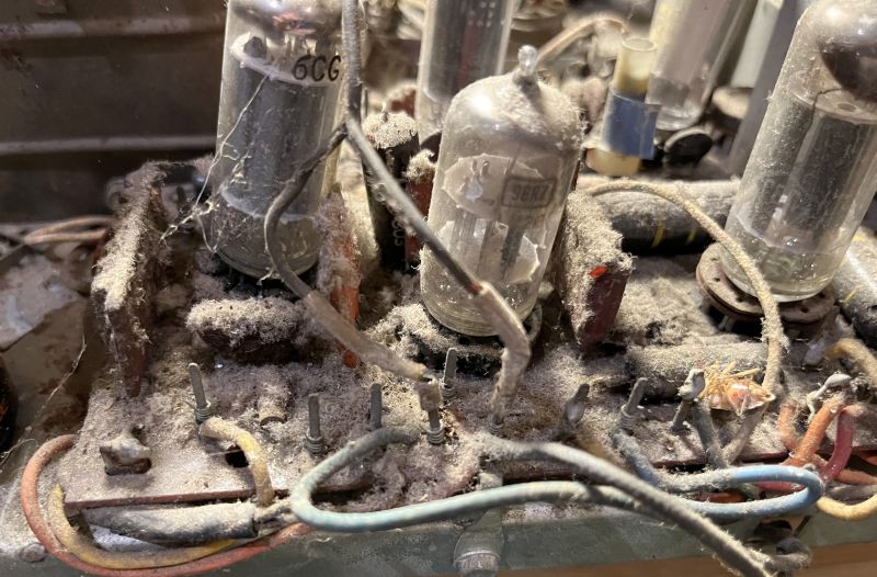
Below is a picture of the IF strip before cleaning with its cover removed.
The chassis contains no power transformer. The chassis is a "hot chassis" as the chassis frame itself is connected directly to the ac power line and can be an electrical shock hazard. The flange portion of the chassis that attaches to the cabinet is electrically isolated from the "hot chassis." There is another isolated flange on the front of the chassis. To safely test the television and to connect test equipment, an isolation transformer must be used. The television has no electrical fuse. A plug-in 5.6 ohm resistor in series with the B+ line acts as a fuse.
Cleaning the chassis was not too difficult. However, the dust was caked onto many components - especially the circuit board. It was difficult to remove all of the caked-on dust and grime from the circuit board.
I replaced most all of the capacitors on the circuit board, except for the small value capacitors in the picofarad range. I discovered numerous resistors had increased in value. As such, I replaced all of the resistors that were more than about 10% out of tolerance. All of the resistors I replaced had significantly increased in value.
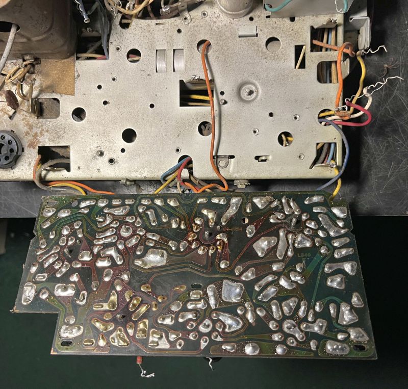
To replace the components on the circuit board, at least half of the 36 connections external to the circuit board via wirewrapped connections had to be removed. In addition, the multiple ground connections had to be unsoldered. To ensure the connections were properly reconnected, I made the connection diagram shown below.
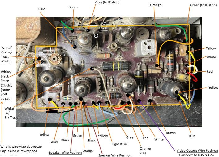
I did not disconnect all of the 36 wirewrapped connections. I disconnected those on the interior of the chassis and along both sides and folded the circuit board over as shown below to gain access to the foil side of the board.
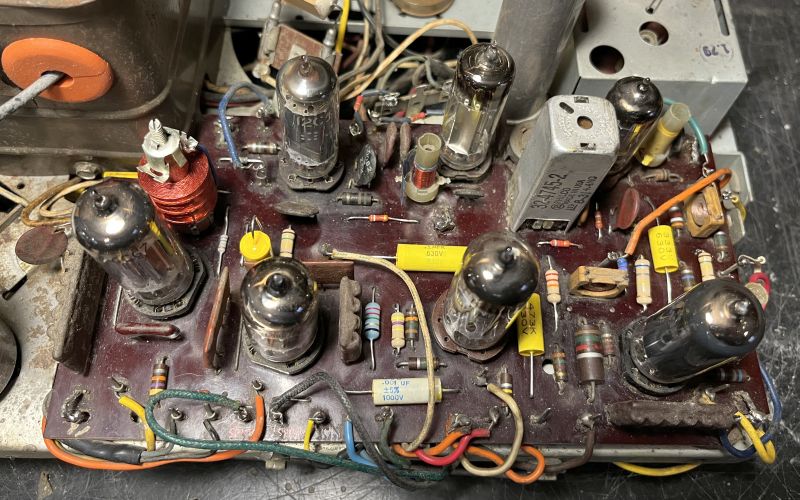
The horizontal oscillator coil was an open circuit. I could not find an exact replacement coil. JW Miller made an exact replacement, but I could not locate one, However, the JW Miller part number 6332 has essentially the same inductance but in a different form factor. The 0.0039 uF capacitor originally designed to resonate the tank circuit at 15,750 kHz can still be used. I had to drill one hole in the circuit board to accommodate the additional pin of the coil form.The picture below shows the restored circuit board with the new horizontal oscillator coil. The large red coil in the upper left-hand side is the replaced coil.
I did not replace any of the couplets (multi-component modules). The few resistance checks I made indicated they were probably good. The vacuum tube sockets are known to crack over time becasue of the heat and often need replacement. I found only one socket had cracked - it holds the audio output vacuum tube. However, only the top layer of the socket cracked but the portion holding the tube pin sockets was still good and the sockets made good contact with the tube pins. As such, I did not replace it. I did not re-wirewrap the circuit board external connections - I carefully soldered them to the wirewrap posts. I also had to repair a couple of the connections that I did not remove because folding the circuit board over broke the solid wires.
I replaced all of the wax paper capacitors and electrolytic capacitors on the chassis. I also replaced several resistors that were out of tolerance. The wire-wound multi-section resistor was open and I replaced it with three individual high-wattage resistors. The restored bottom-side of the chassis is shown below.
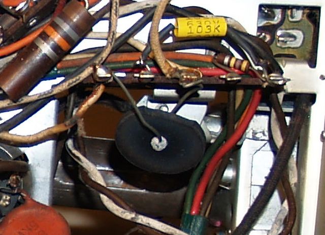
The circuitry includes a thermistor in series with the filament string to limit the inrush current to the vacuum tube filaments when the television is first turned on. This feature prolonged the life of the vacuum tubes. The original thermistor is shown below.
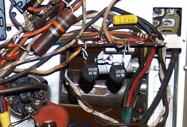
The original thermistor was open circuit. The SAMs Photofact schematic indicates the original thermistor should measure 400 ohms when cold and 11 ohms when hot. To replace this defective component I wired two Amertherm SL12 22101 thermistors wired in series. The specifications for the Amertherm SL12 22101 indicate the resistance is 220 ohms when cold and 4.2 ohms when hot and passing 1 Amp. The picture below shows the two replacement thermistors.
The flyback transformer, sealed in tar, was good although the tar is cracked and some of the tar dripped down because the transformer gets hot during operation. Below are pictures of the flyback transformer with its protective cage removed. In the second picture below you can see that a resistor is shorted by a jumper. This jumper was installed in the factory.
Below is a picture of top of the restored chassis. The rectifier diode block had been replaced during a repair long ago. The diodes are standing up in free space and can be seen to the upper right of the antenna connection panel. This repair could be a safety hazard if something touched the diode leads. I placed a cardboard tube (not shown in the picture) over the diodes to minimize the hazard.
I tested all of the vacuum tubes. Two tubes tested weak and I replaced them. Those tubes were a 3BZ6, the second IF amplifier, and the 3AU6, the sound IF amplifier. The audio output tube is supposed to be a 12CA5; however, a 12C5 was installed instead during a previous repair long ago. It tested good and works well. I also replaced both dial lamps - one in the VHF tuner and one in the UHF tuner.
After the above restoration, I reconnected the chassis to the CRT again and slowly powered it up with a variable transformer while measuring the B+ voltage. The first raster is shown below.
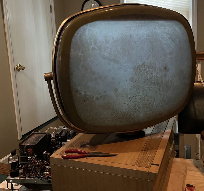
In the picture above, the CRT cover material degradation is clearly evident. Below is a picture of the first crosshatch image.

The above images were produced by injecting a signal into the antenna terminals on Channel 3 using my B&K Precision 1248 Digital IC Color Generator. Further tests using my B&K Model 1077 Television Analyst showed the television would not receive any channels above Channel 8. Spectrum analyzer measuremens of the television local oscillator showed no oscillator signal present for channels higher than Channel 8.
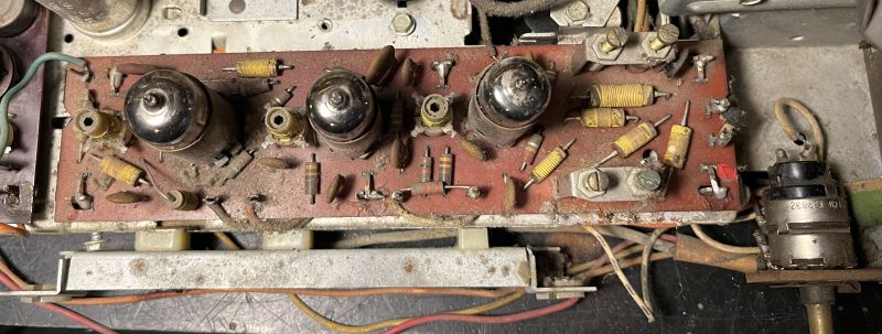
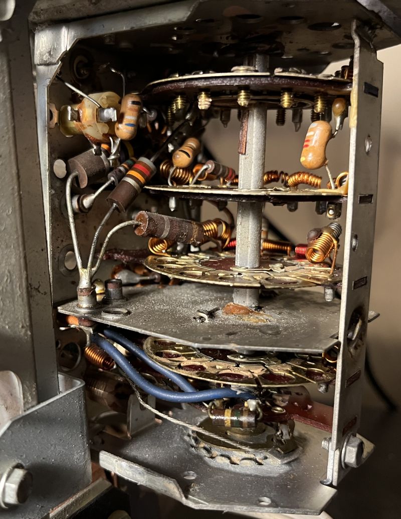
The VHF oscillator tube tested good. Proper oscillator operation can be finicky if the oscillator tube is not properly biased. As such, I measured resistors inside the VHF tuner. The picture below shows the VHF tuner with its cover removed in its original condition.
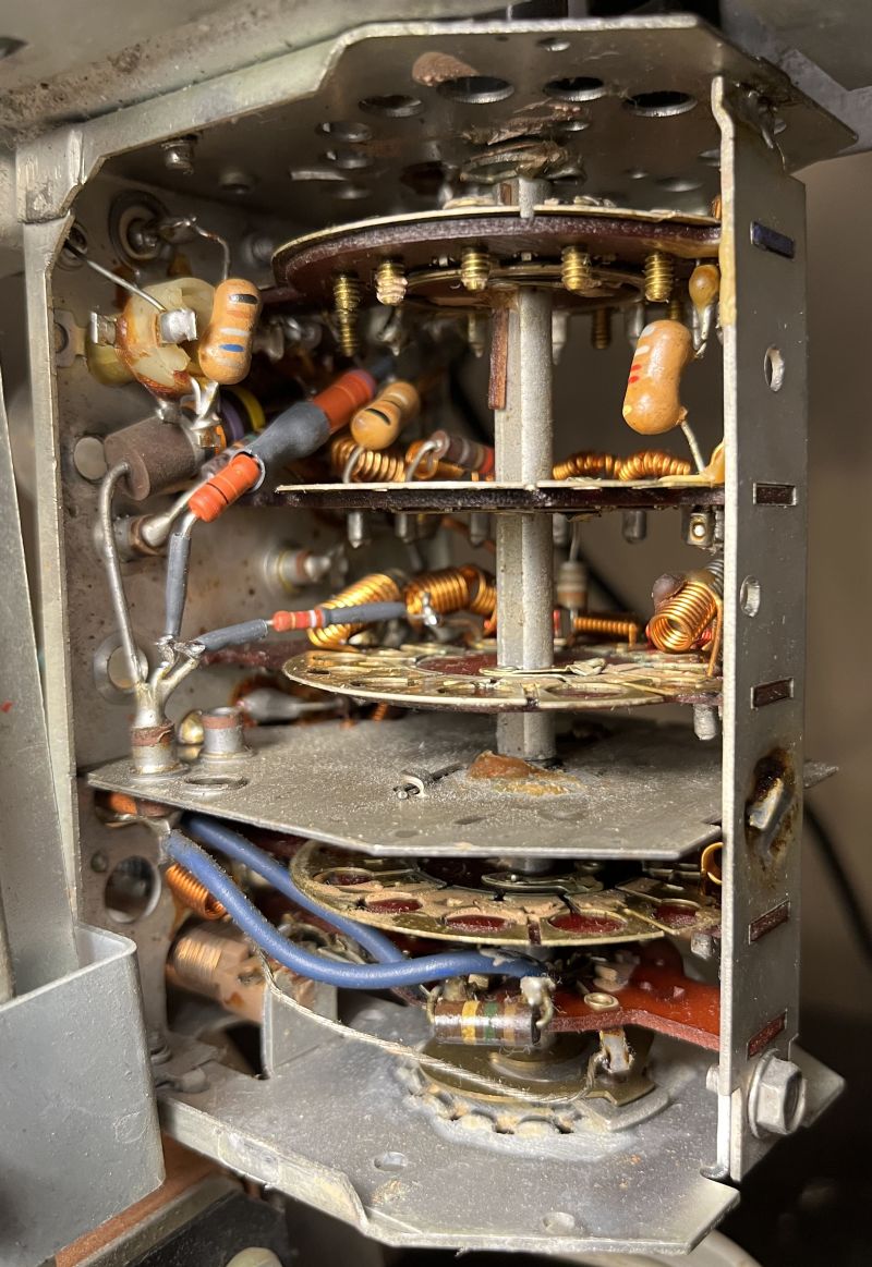
An 82k ohm resitor in the B+ supply of the oscillator tube produced odd resistance readings - it would read low and high resistance during several attempts to measure its resistance. Heating the resistor did not immediately change the resistance readings, but the resistance dropped as its temperature returned to room temperature but then increased again to slightly above 82k. In addition, a resistor in the B+ of the VHF RF amplifier tube measured consistently high. I changed both resistors. I did not have a 1 Watt 82k ohm resistor handy so I placed two resistors in series to produce 82k. The replaced resistors are shown in the picture below.
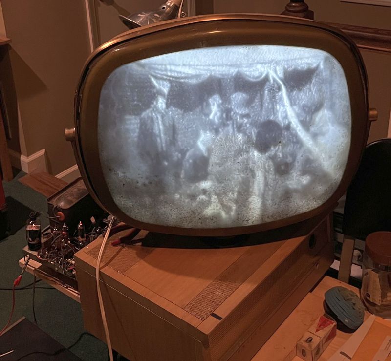
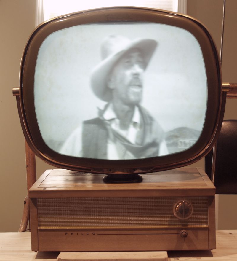
After the above, the television receives on the higher channels. Below is a picture of the television receiving a television program. The CRT cover material degradation is clearly evident in the image.
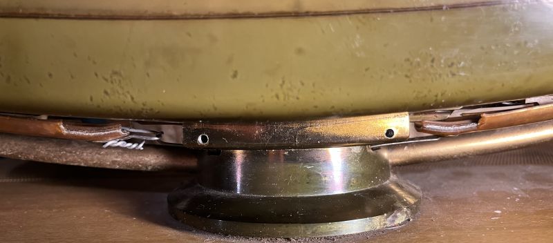
To address the material degradation of the CRT cover, the gold-colored plastic trim strip surrounding the CRT must be removed. It is held in place by an extremely stiff spring at the base of the CRT in the swivel mount. Removing a decorative brass plate on the front of the CRT mount reveals the spring. Needle-nose pliers and some muscle is required to disconnect one end of the trim strip. A metal strip with multiple holes in it underneath the trim strip holds both the CRT cover and the rear CRT beige plastic cover in place. It is held in place by a screw at the base of the CRT. I did not have to completely remove it to remove the front cover. The picture below shows the CRT with its cover removed. You can see some of the CRT cover material on the CRT face.

Windex easily cleaned up the CRT as shown below.
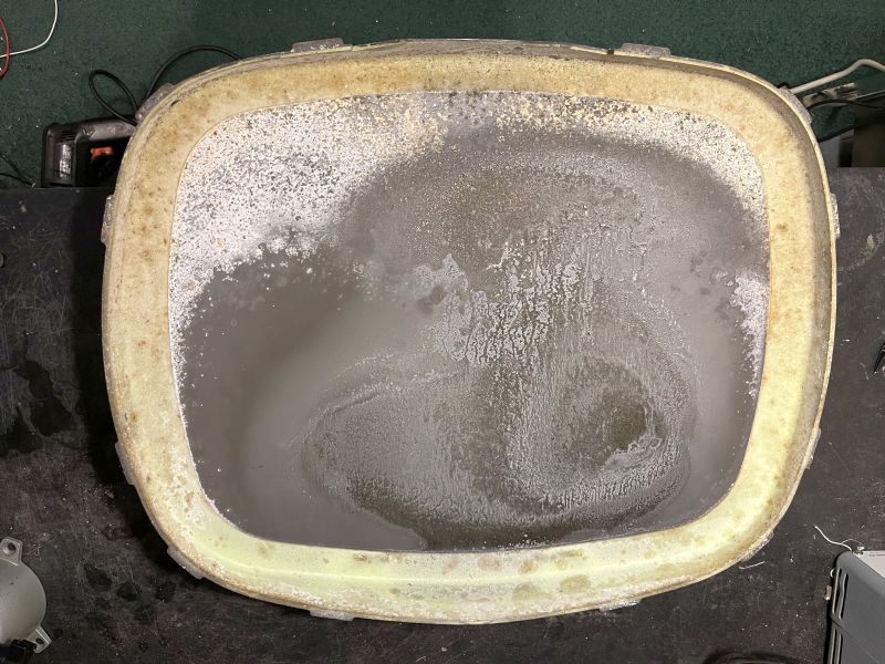
Below is a picture of the inside of the CRT cover. The waxy, chalky buildup is clearly evident. This material degradation is why the video image looks so bad.
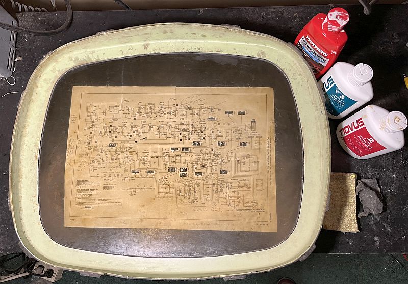
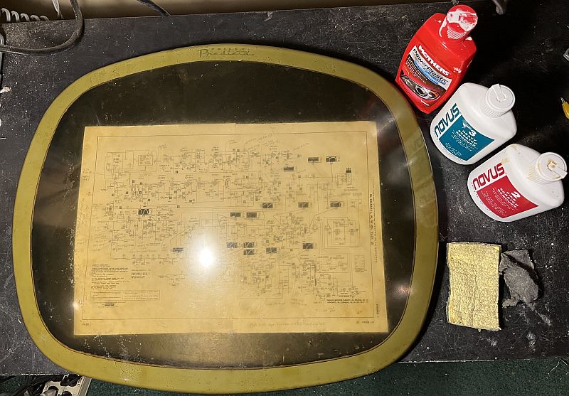
Cleaning the cover took patience and time. I cleaned both the inside and outside of the cover using Mothers NuLens headlight renewal polish and Novus Number 3 and Number 2 plastic polish. I also used a Scotchbright pad and 0000 steel wool to remove all of the material degradation. The pad and steel wool did not seriously scratch the cover. The results of the cleaning are shown below. The cover is now transparent but with the iconic greenish tint.
I could not do much about the pitting. The pitting is evident with the television off, but does not seriously affect the television video image. The picture below shows the television off with the restored cover. The picture makes it look worse that it actually appears.

Re-mounting the cover and the metal strip that holds both the CRT cover and the CRT rear cover is fairly straight-forward. However, re-mounting the gold-colored plastic trim strip is nearly impossible because of the extremely stiff spring at the base of the CRT in the swivel mount. In addition, the CRT rear cover appears to be warped compared to the CRT front cover (or vice versa). I tried several times but could not pull the stiff spring out a distance sufficient to hook it into the hole in the trim strip. To mount the trim strip, I made a loop from aluminum wire to extend the trim strip approximately 1 inch. With this addition, I could fairly easily pull out the stiff spring and insert it into the loop. The spring tensions the trim strip sufficiently such that the trim strip will not slip off. This modification is shown below.
A metal trim piece in front of the swivel pedestal covers up this modification and as such, it cannot be seen.
As stated above, the original telescoping whip antenna was missing, presumably because it was accidentally broken as is often the case. Only the 3 holes in the cabinet for mounting that antenna remain. I fabricaed an aluminum plate to mount a female F-connector feedthrough to the cabinet. That can be seen in the picture below.
I acquired a 300-ohm-to-75-ohm transformer and fabricated a short piece of RG-6 cable to connect the internal part of the F-connector feedthrough to the transformer and then connected the 300-ohm transformer leads to the 300-ohm antenna inputs on the back of the chassis. That can be seen in the picture below to the upper left of the antenna connector panel. (The cardboard tube I placed over the rectifier diodes can also be seen in the picture).
I purchased a long telescoping whip antenna with a male F-connector for the antenna. That can be seen in the picture below. It does not look exactly like the original antenna but its location and functionality are the same as the original. It works quite well.
The television on/off switch is integrated into the volume control. The television is turned on and off by pushing in the volume control. However, in this example, the ratchet that maintains the on/off condition malfunctions. The switch contacts are good, but the television will not stay on when the button is pushed. During a previous repair long ago, the on/off switch was bypassed, leaving the television permanently on.
Considering the power cord has been cut, I integrated a toggle switch into my repair of the power cord. I also integrated an external fuse holder into the power cord. I made a bracket for the toggle switch and mounted it to the top rear of the cabinet as shown in the picture below. To turn the television on and off, one has to reach behind the CRT and flip the switch. The original safety plug was frayed a bit at the strain relief, so I applied epoxy around the strain relief to prevent further fraying and to prevent a possible short circuit. I used a tie wrap to secure the new power cord to the back and act as a new strain relief.
Below are video images taken after restoration.
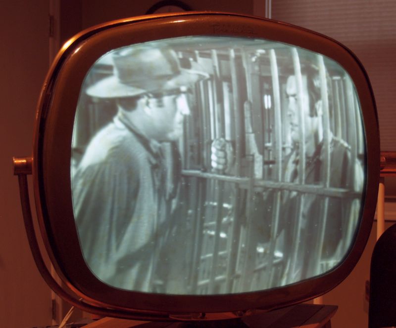
Below is a short video showing the television receiving a television program.
Below is an advertisement for the Philco Predicta Holiday television receiver. Note that my television in the blonde cabinet sold for $279.95 in 1958/1959.
Below are other advertisements for this Philco Predicta television.
Tube Compliment
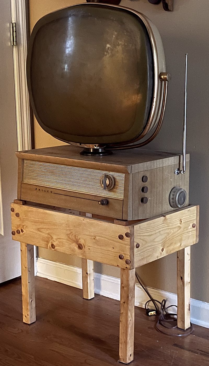
I constructed a stand for the television to make it "self supporting" similar to a console television. The television on the stand is shown below. The stand is an open frame such that air can flow through the cabinet. The bottom of the cabinet is a perforated metal screen to facilitate air flow through the television cabinet.
The screen removed from the television is shown below. The picture shows the inside of screen.
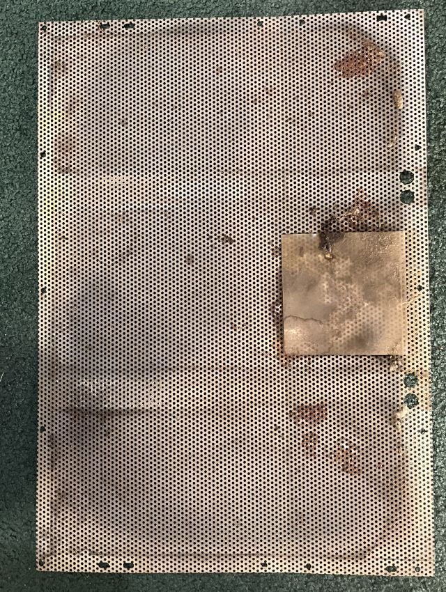
The bottom of the restored television with the screen removed is shown below.