Pilot Radio Model TV-37 "Candid" Television Receiver
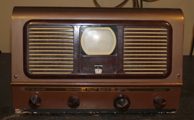
This page describes a Pilot Radio Model TV-37 Television Receiver monochrome (black and white) VHF televison reciever, manufactured in 1948. This television is housed in
a perforated sloped cabinet with a wood base. The television has no power transformer and is light weight. The chassis is connected to one side of the ac power line when on.
As such, an isolation transformer must be used when servicing this television.
This television is unique in that it incorporates a tiny 3-inch diameter 3KP4 picture tube (CRT). This television was marketed to college students and those that live in large-city,
small apartments because it is small and light weight. The television sold for $99.
The televison receives all 12 analog VHF channels separated into two bands - it does not receive the analog UHF televison channels. The low band continuously tunes TV channels
2 through 6. The high band continuously tunes TV channels 7 through 13. The television does not have the typical "click stop" tuning.
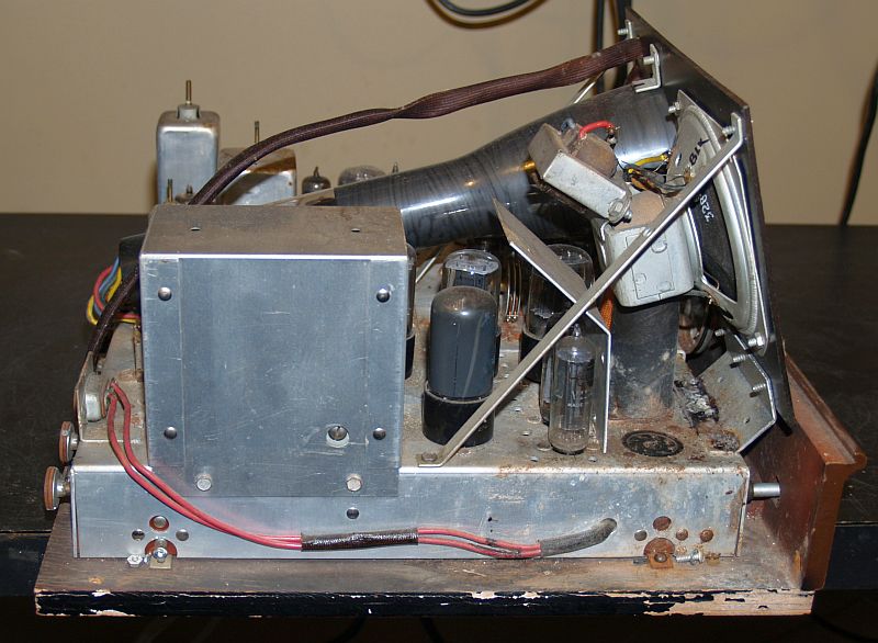
The pictures below show the sides, rear, and bottom of the television.
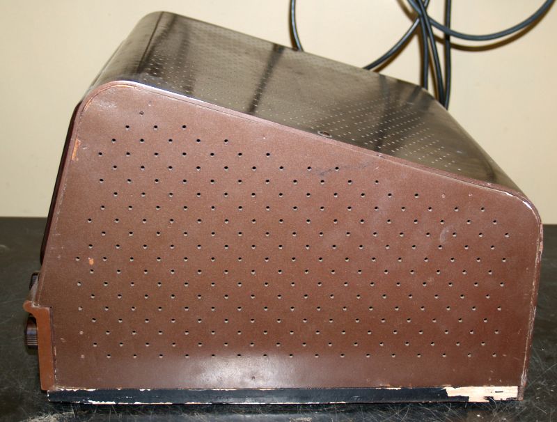
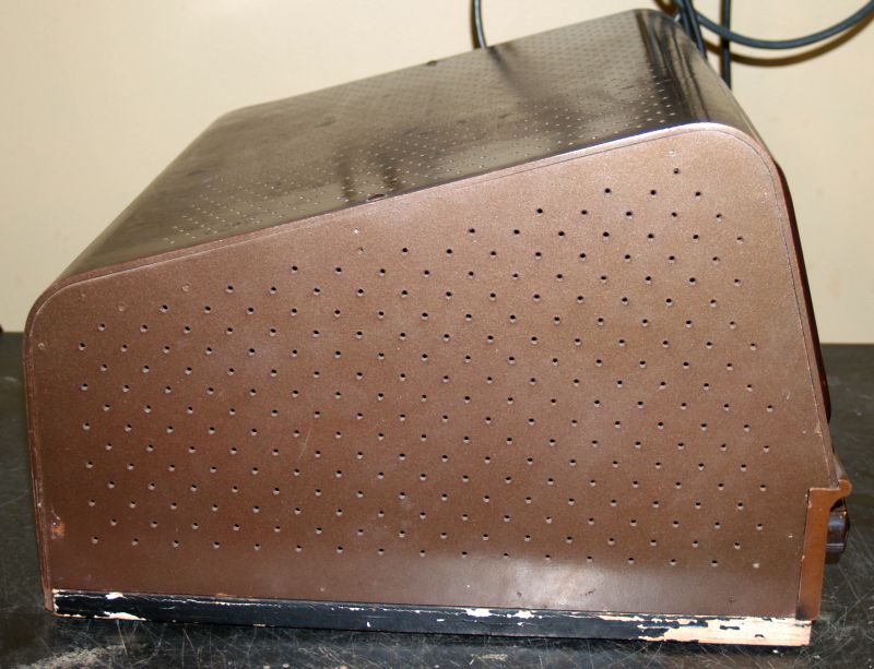
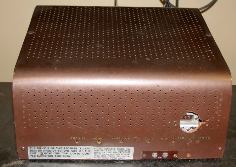
As seen above, someone previously removed the safety ac power cord interlock and cut a large hole in the cabinet to attach a "cheater cord."
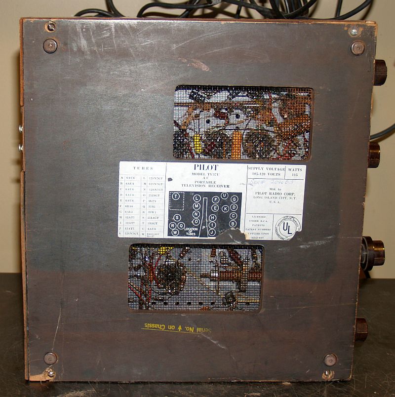
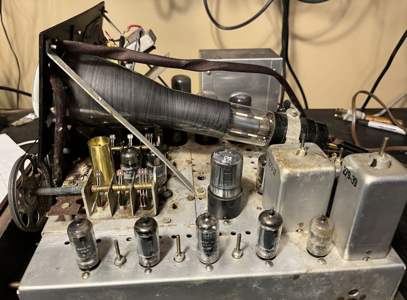
Below are pictures of the chassis as received when removed from the cabinet.
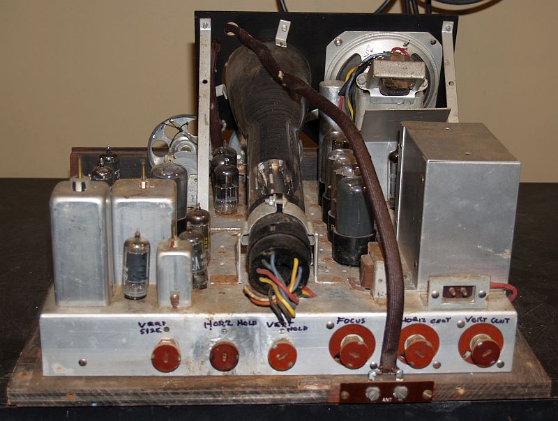
As seen above, someone labeled the control functions on the rear of the chassis. These controls are unusual in that they have an insulated cap on the
control shaft and the right-hand three controls in the picture above are insulated from the chassis. There are hazardous voltages on all of the controls. One
must take care to not touch the metal parts on these controls when servicing this television.
The picture immediately above shows a tube socket without anything plugged into it. There should be a ballast tube there to drop the line
voltage.
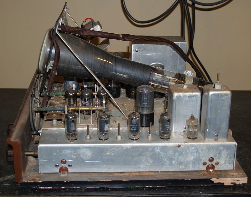
The chassis is mounted to a wooden board to which the lower wooded portion of the television front is attached. The picture below
shows the underneath of the chassis after detachment from the wood bottom.
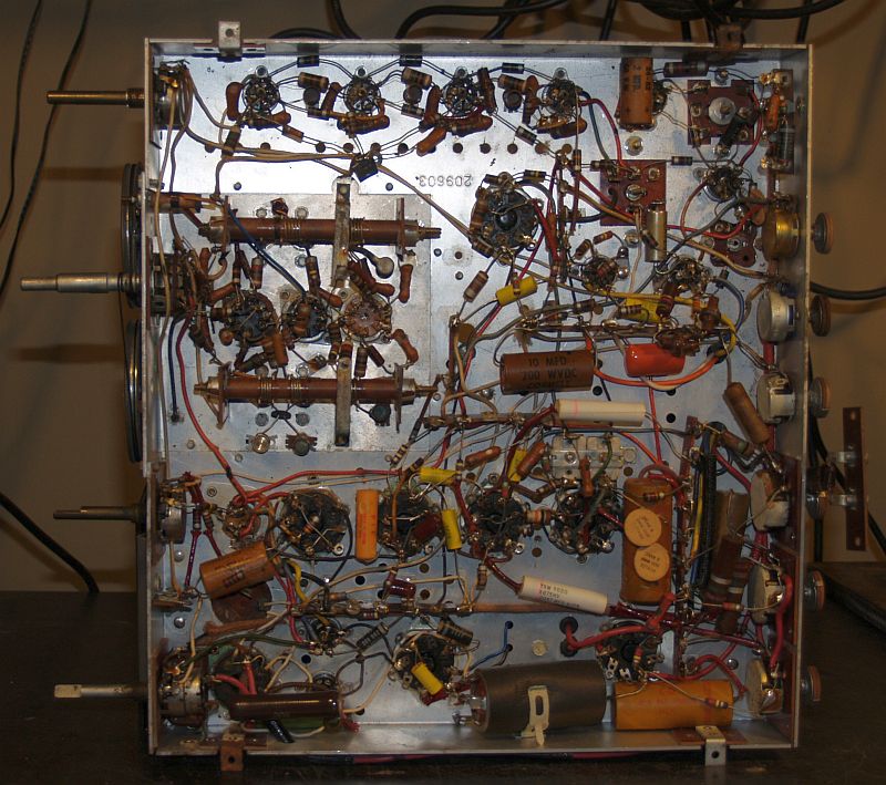
As evident in the picture above, this television had been mostly restored sometime in the past. In particular, there are numerous yellow-colored
capacitors throughout, indicating these are new capacitors that replaced the older wax paper capacitors. In addition, there is a brown wire-wound
power resistor underneath the ballast tube socket that can be seen in the lower left in the picture above. The resistance measured 484 ohms. This
resistor is a replacement for the ballast tube. However, four high-voltage (2 each 1kV and 2 each 3kV) capacitors had not been replaced.
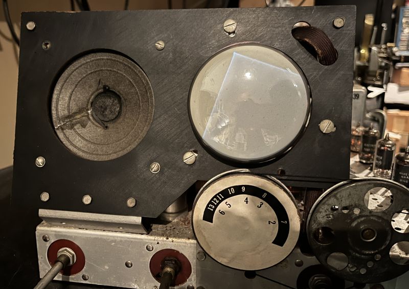
I brought the television up slowly with a variable ac transformer. Initial tests indicated no sound, but the picture tube did produce a dim raster off center and tilted.
The picture below shows the first raster that I observed. This test indicated the picture tube is good. These televisions are often found with a defective picture tube and
sometimes the picture tube is replaced with a more readily-available tube typically used in oscilloscopes that produces a green image.
Initial tests also indicated poor or no reception from my B&K TV Analyst. I decided to investigate the lack of sound first.
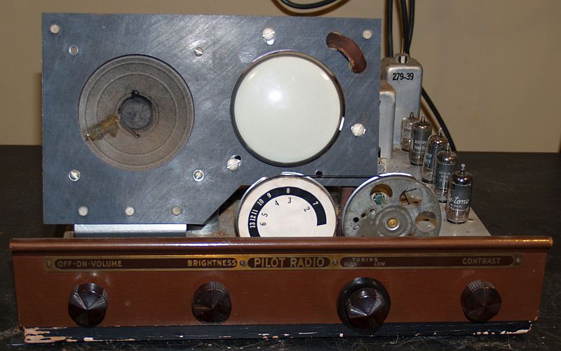
The picture above shows the speaker (after I determined the problem and quickly rewired it for testing). Wiring around the speaker is a mess with wire connections that are not insulated.
The speaker appears to be a replacement, possibly taken from another Pilot television.
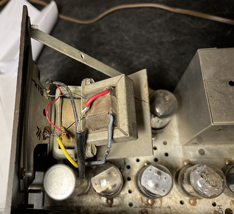
The speaker is an electrodynamic speaker with the speaker field coil in the power supply filter circuit. Resistance measurements indicated the filed coil and the voice coil were good.
Diagnosis indicated one end of the voice coil was not connected. This speaker is a bit unusual in that one side of the voice is wired to ground, consistent with the schematic. This situation
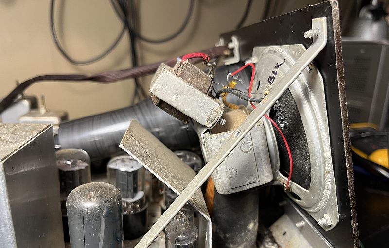
may have confused the previous restorer. To correct the problem, I had to disconnect one of the connections and wire it the non-connected voice coil connections. My connection is the long red wire
seen in the picture below. The audio section now works and produces undistorted audio after rewiring.
The television did not produce an image from my TV Analysit, when injecting the signal into the IF strip. Circuit tracing and analysis indicated an open 390 uH inductor in the plate circuit
of video amplifier. I replaced it with a 390 uH inductor. After replacing the inductor, the video IF section works.
The television will produce an image when an IF signal is injected at plate of RF mixer vacuum tube. The IF seems to be properly centered in frequency. The image was not particularly bright
and the image resolution was not particularly good.
Each of the two TV frequency bands incorporates a three-section "ganged" variable capacitor. The low band and high band ganged variable capacitors turn with a single dial cord. The two capacitors
were not aligned and the tuning dial would not rotate through its full range. I loosened the dial string spring and aligned the low and high band ganged variable capacitors. The dial now rotates
through its full range.
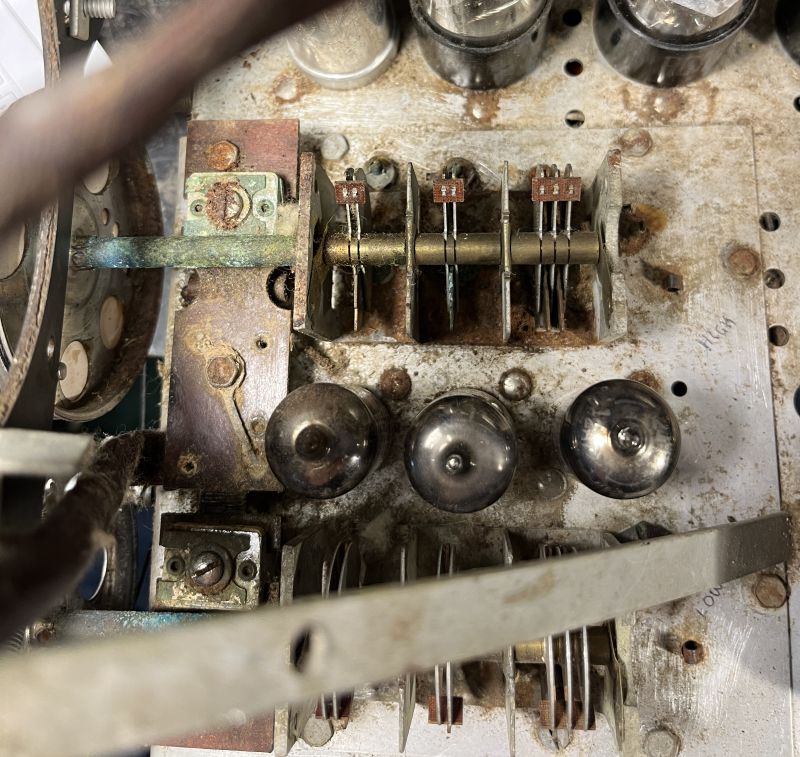
The local oscillator does work in both low and high bands. Frequency checks at the high and low ends of the dial indicate the local oscillator frequency is approximately correct. However, initial tests
indicate no conversion by the low and high band mixers. The 12AT7 mixer vacuum tube tested good. As shown in the picture below, the RF deck is severely corroded and rusted such that some of the
internal service tuning capacitors are frozen and cannot be turned.
The tube socket receptacles of many tubes in the television are severely corroded. I sprayed DeoxIT in the sockets, cleaned the tube pins, and srayed DeoxIT on the tube pins and reinserted the
tubes into their sockets several times. The mixer now downconverts, but the receiver sensitivity is low. The RF amplifier tube, 12AT7, tested good.
The television did not produce a clear and bright image when injecting RF at the antenna input. Tests indicate there may be minimal gain in the high band RF amplifier.
I sprayed DeoxIT in the RF amplifier socket again and srayed DeoxIT on the RF amplifier tube pins and reinserted the tube into its socket several times. The low band now seems to have reasonable
sensitivity and it will receive a television program on Channel 3 when I injected an RF signal from my over-the-air (OTA) HDTV to analog TV converer box. However, I could not receive good sound
with a clear picture.
While receiving the OTA signal, I adjusted the IF tuning coils and the sound IF coils and eventually was able to receive reasonably good video along with clear sound on the low band. Eventually,
I conducted a full alignment of the video IF and sound IF to confirm alignment. The high band, Channels 7 through 13, will not receive a clear image from my TV Analyst. The images received on the
high band appear negative, indicating possible saturation of the receiver. The images and sound recevied on the low band are acceptable; however, there is a horizontal interference bar that
creeps up from top to bottom making the image not viewable. If the bandswitch is switched from low to high and back to low, the low band image appears good for approximately 3-4 seconds
before the horizontal interference bar reappears. This situation suggests there may be oscillations, perhaps in the RF front end, that start shortly after power is applied to the low band front end.
Varying the contrast control, that acts like a gain control, or varying the line voltage, have no effect on the presence of the horizontal interference bar.
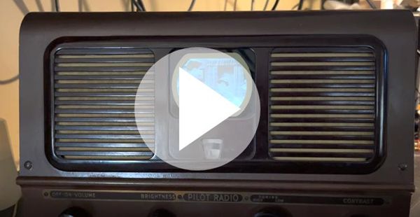
After significant trial and error, I detuned the tuned circit at the mixer input and the oscillations stopped and I can received a good picture when injecting an RF signal from my over-the-air (OTA) HDTV to
analog TV converer box on Channel 3. Click on the image below to see a video of the television receiving a program.
The television still seems susceptible to oscillations on occasion. Wiggling or reseating the RF amplifier tube and the first tube in the IF strip often solve the problem. I made a tube shield from brass
sheet stock and placed it over the RF amplifier to perhaps minimize the possibility of oscillations. This tube shield is shown below.
Although the television works with a high-level signal injected into the antenna terminals when operating on the low band, the television has minimal, if any, image rejection.
I believe this situation may be caused by the severely rusted RF deck. The RF amplifier appears to provide minimal gain and minimal rejection of signals outside of the tuned TV channel. No clear signals
can be received on the high band. One can touch the RF input to the mixer and FM radio stations can be heard. The television will receive a signal on Channel 5 when broadcasting
from an in-house analog television transmitter.
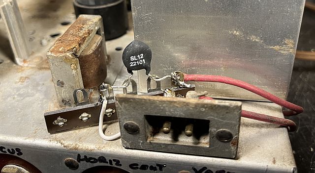
Because a replacement for the 3KP4 CRT is not readily available, I added an Amertherm SL12 22101 NTC inrush current limiter in series with the ac power line to provide a soft startup. The installation is
shown below. I mounted the current limiter to a terminal strip. I rerouted one wire from the power connector to the terminal strip and one connection of the current limiter. The other
connection of the current limiter was connected to the ac power connector where the wire was previously connected.
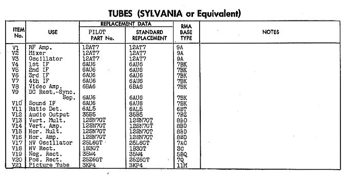
Below is the television tube compliment.
Below is a video of the assembled television receiving an OTA program ("Leave It to Beaver").