RCA Model 8-PT-7030 "Personal" Television Receiver
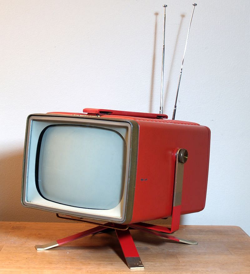
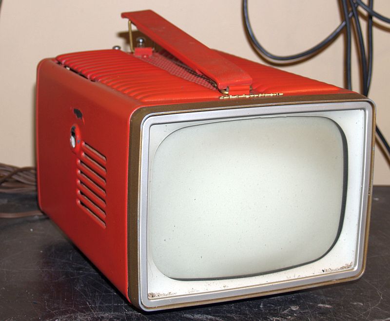
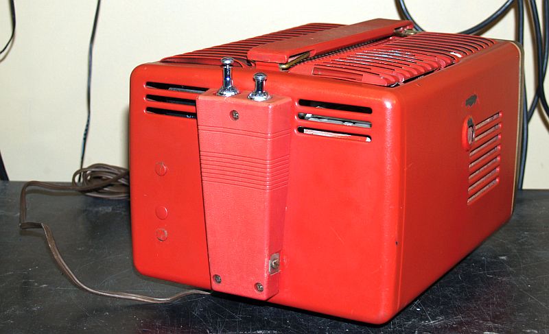
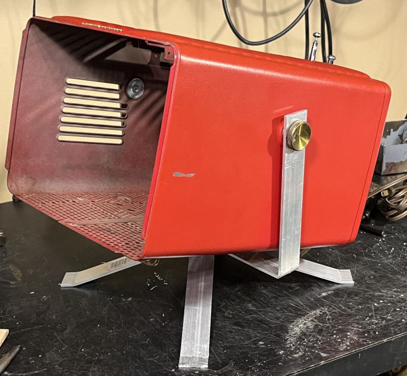
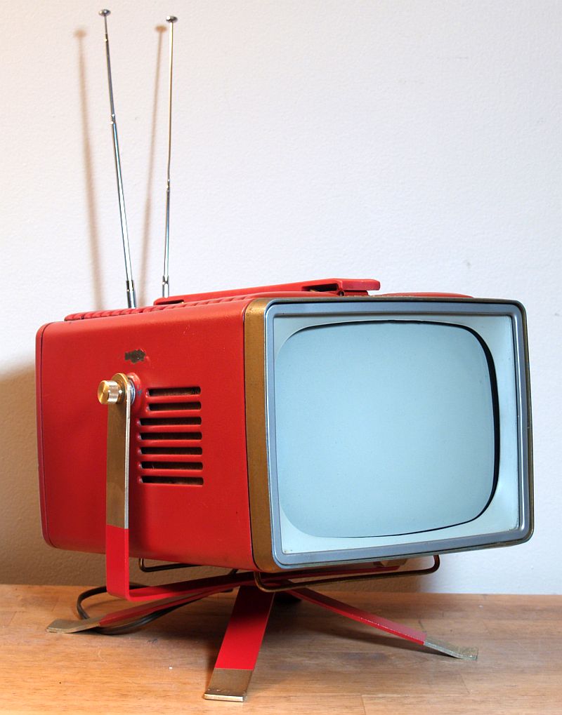
This page describes an RCA Model 8-PT-7030 "Personal" monochrome (black and white) televison reciever, manufactured in 1956. The Model 8-PT-7030 pictured above
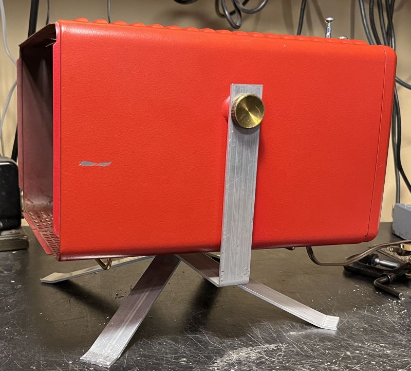
is painted red and includes an adjustable stand for viewing at the optimum angle. The stand can be removed for portability. The original stand for this
particular example was missing when I received the television. The stand shown in the above picture is a stand that I replicated from pictures I found on line.
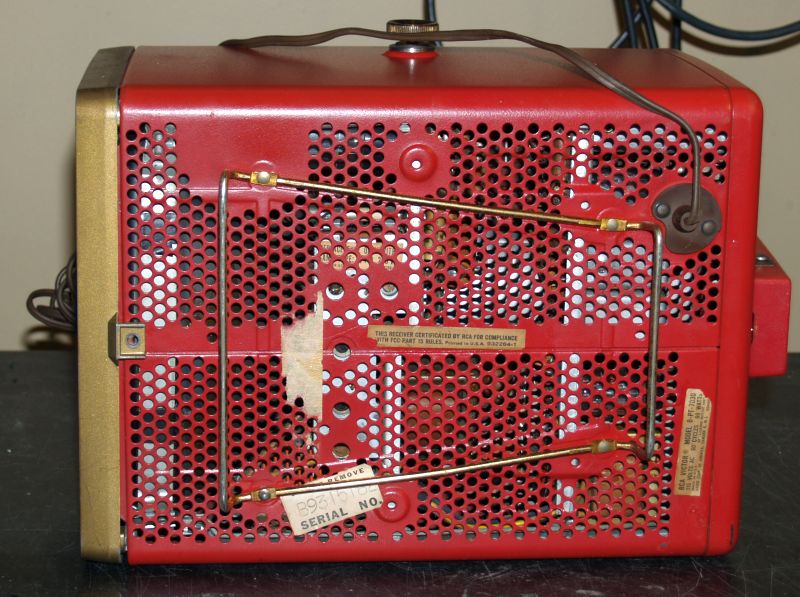
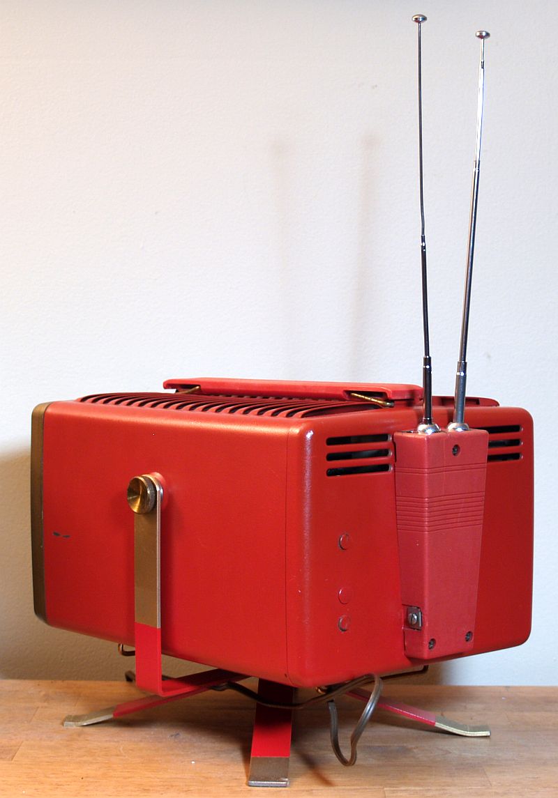
The televison receives all 12 analog VHF channels - it does not receive the analog UHF televison channels. The television includes two adjustable rod-type antennas mounted on
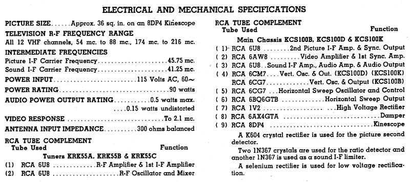
the rear of the cabinet. The television includes an 8-inch 8DP4 monochrome cathode ray tube (CRT) that provides an approximate 36-square inch viewing area.
The television is small, measuring 13 inches deep, 8 5/8 inches wide, and 8 3/4 inches high, including the permanently-mounted wire stand mounted on the bottom. The television
is portable but is somewhat heavy because the power supply includes an internal transformer and its cabinet is made of steel. A handle on top facilitates transportation.
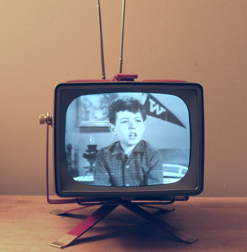
Below is a picture of the restored television receiving an on-air analog program ("Leave It To Beaver") from my in-house analog television transmitter.
Below are the specifications and tube compliment for this television.
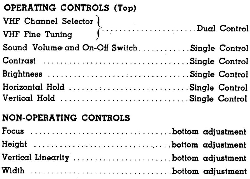
Below is a description of the external and internal controls for this television.
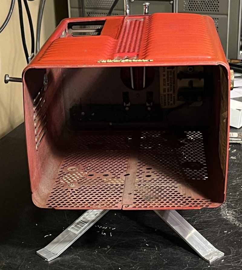
Below are pictures of this televison when I received it.

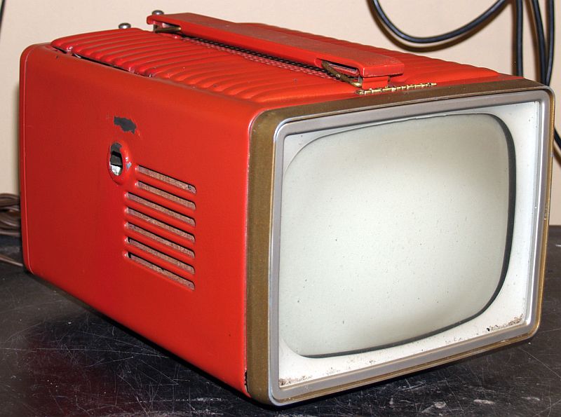
One receptacle for the thumbscrew that holds the removable stand is missing as seen by the empty hole in the side of the cabinet shown above.
The televison has a small wire stand permanently mounted to the bottom as shown above. The screw near the front of the bottom is missing.
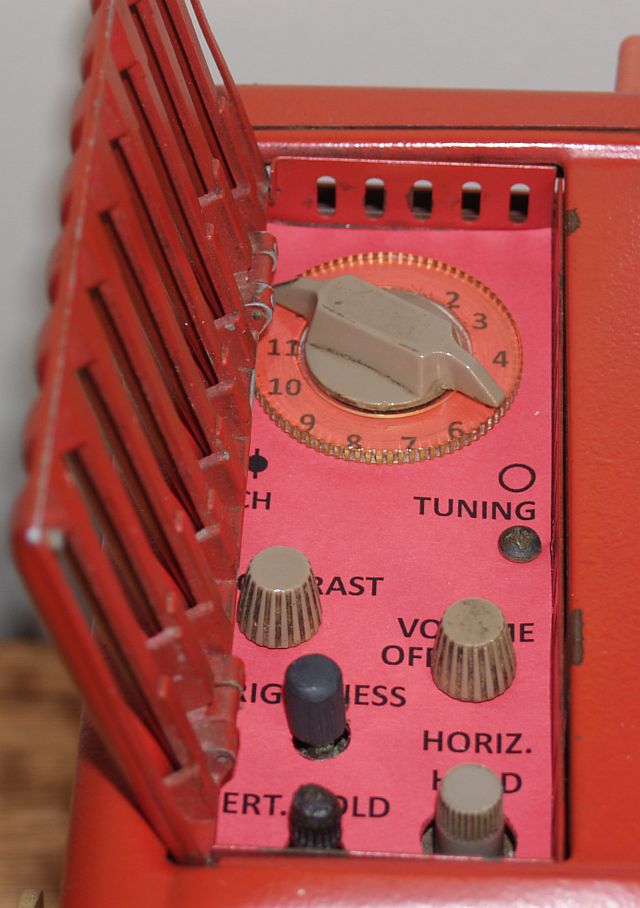
The external controls are located underneath a hinged cover on top of the television as shown below.
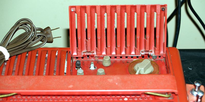
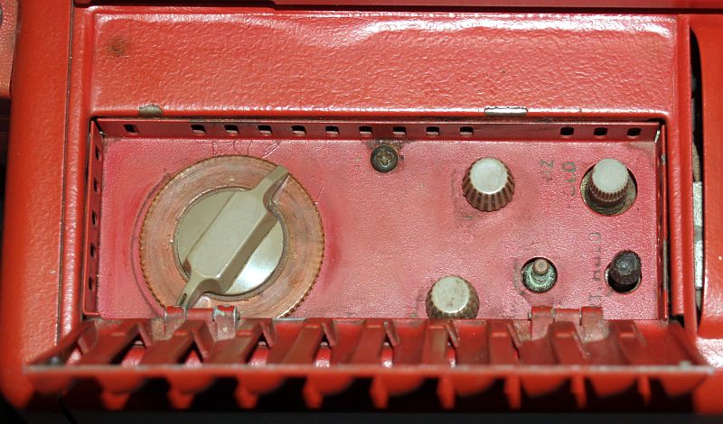
The control legends have mostly disentegrated as seen in the picture above. In addition, one of the black knobs is partially missing.
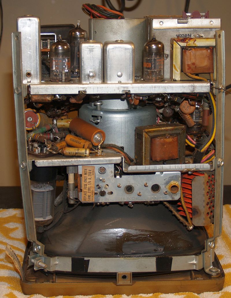
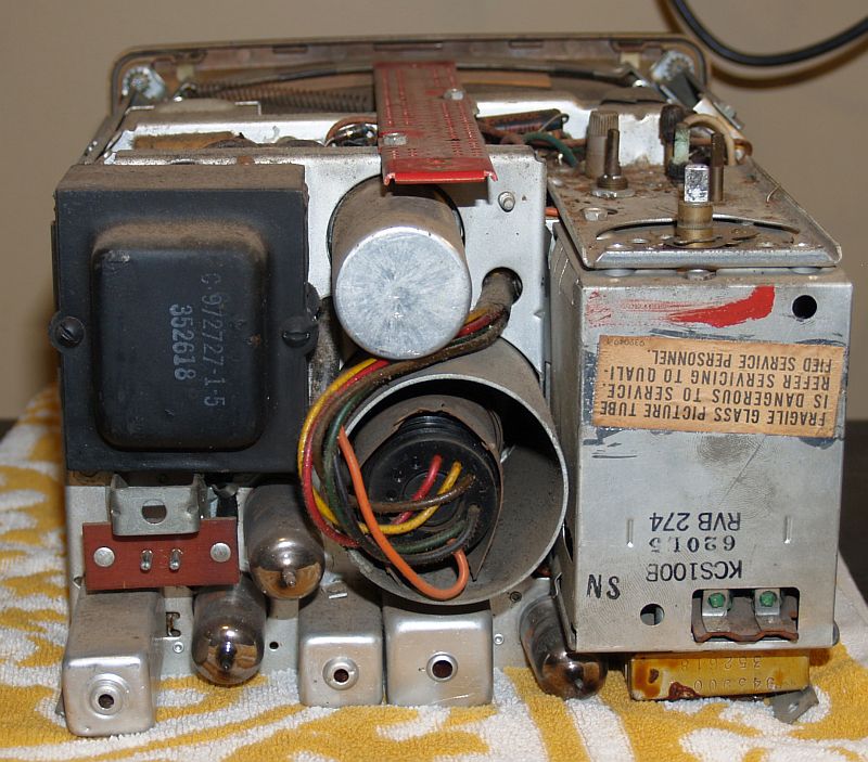
Below are pictures of the chassis when removed from the cabinet.
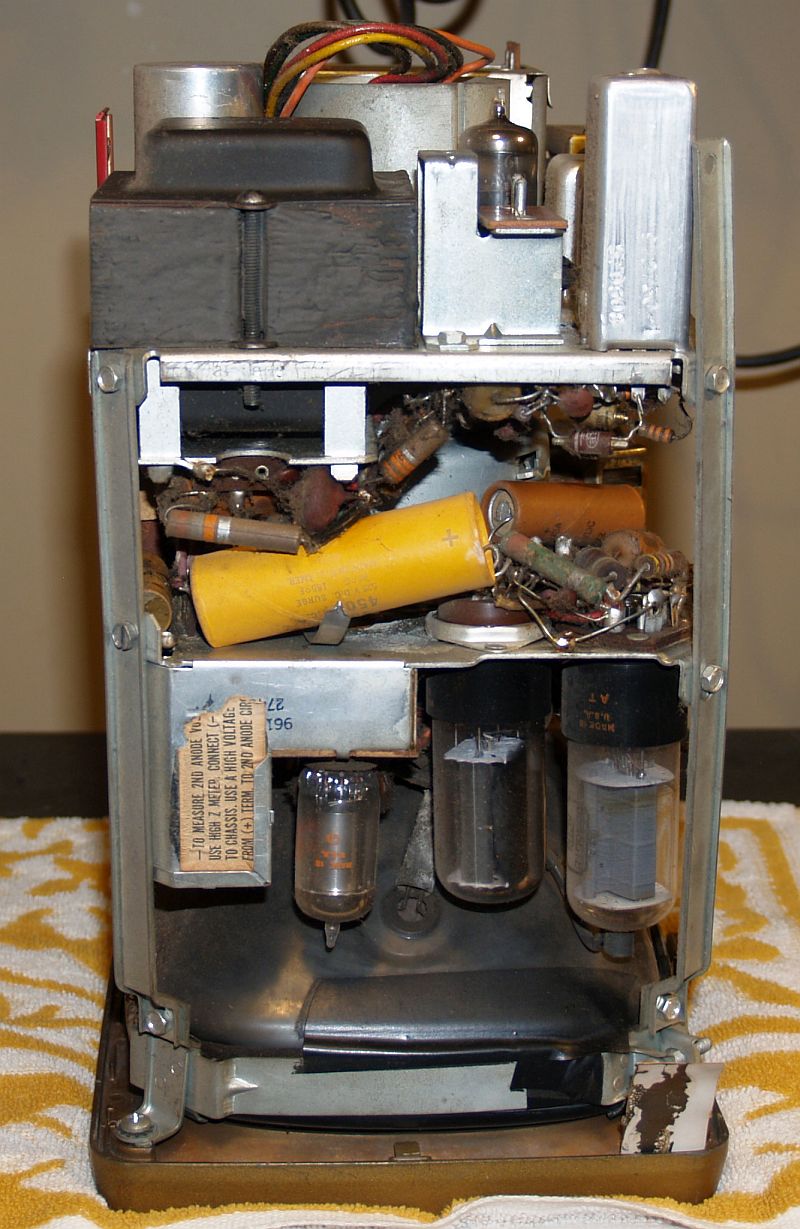
The television has a selenium rectifier in the power supply. It can be seen as the orange-colored rectangular device with several fins (plates)
in the lower right of the picture above. I did not replace the device, nor did I replace the power supply filter capacitor as the television works
well with those devices.
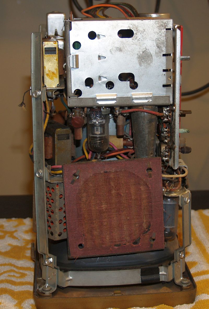
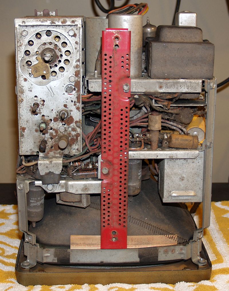
There should be four or five perforated cardboard dust covers on the sides of the chassis. These dust covers are missing on this television.
The television comprises two chassis held together by three longitudinal metal bars and a tab on the tuner. The two chassis can be separated by removing six
screws and the red metal piece on top to which the handle attaches. There is suffient length to the CRT socket wires so that the two chassis can be separated to
gain access to most all components without disconnecting the CRT socket from the CRT.
This television did produce a raster when I received it. As such, at least the CRT was known to be good. However, the television would not synchronize to the
signal produced by my B&K Televison Analyst. Investigation into this situation yielded that the horizontal oscillator was operating at a frequency much lower than
15,750 Hz.
I wrapped a loop around the horizontal oscillator tube to observe its waveform and measure its frequency as shown below.
The horizontal oscillator measured 14.218 kHz, that is much too low for the television to synchronize to a television signal. The picture below shows the
unsynchronized raster, the oscillator waveform, and the frequency as measured by a frequency counter.
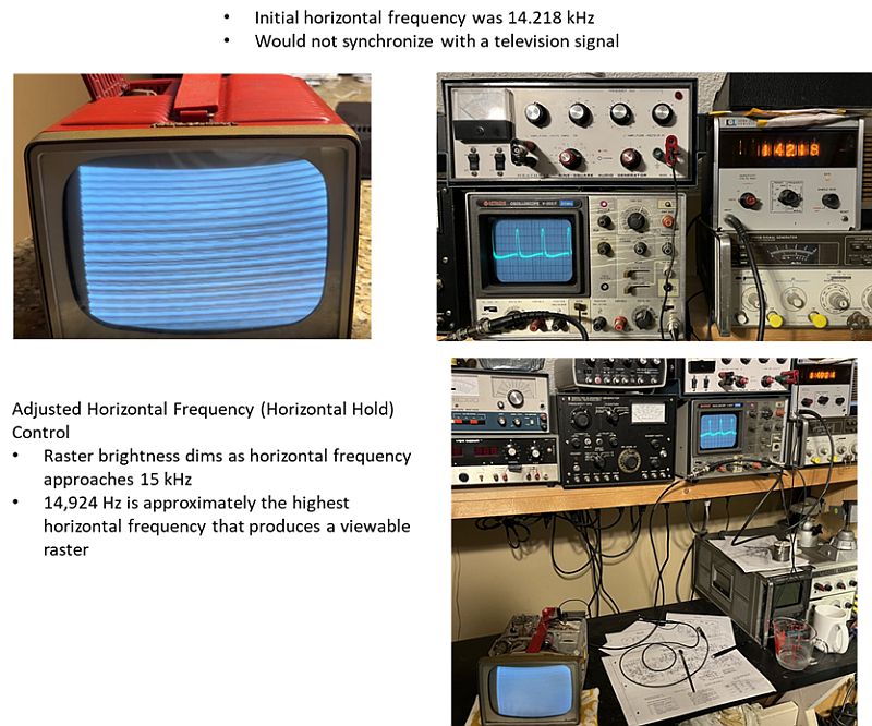
The external horizontal hold control adjusts a ferrite slug in a coil. As such, it has a wide range of adjustment, but when the television is operating properly, it
is not required to adjust it often. I turned the horizontal hold control to increase the frequency. The raster brightness dimmed as horizontal frequency approached 15 kHz.
A frequency of 14,924 Hz is approximately the highest horizontal frequency that produced a viewable raster. This situation indicates the capacitors that determines the
oscillation frequency are significantly out of tolerance.
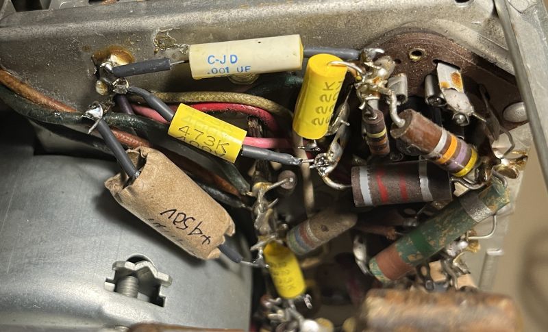
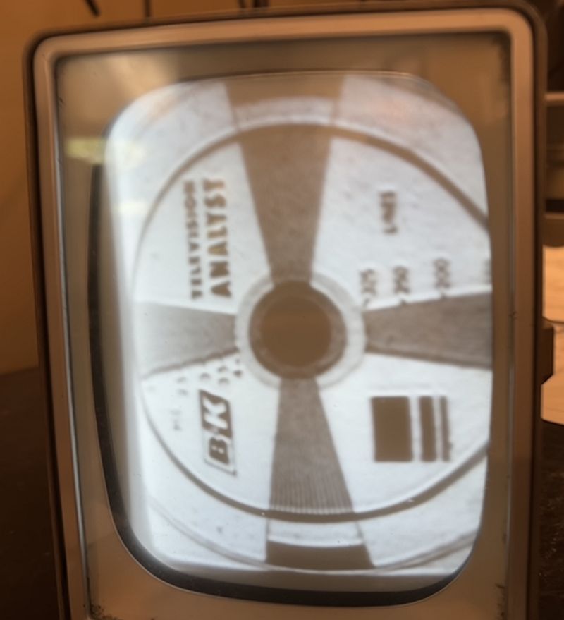
Replacing three wax paper capacitors in the horizontal oscillator circuit increased the retuned horizontal frequency to over 16 kHz. Retuning the horizontal frequency to 15.75 kHz
allowed the television to synchronize to my B&K Television Analyst RF signal. The horizontal size, vertical size, and focus still had issues, though, as shown below.

When replacing the wax paper capacitors in the horizontal oscillator circuit, I also replaced an electrolytic capacitor in the power supply circuit. It had been replaced
during a previous repair long ago. The capacitor is originally designed to be 60 uF, but was replaced with a 40 uF. I used a 47 uF capacitor. I also replaced a wax paper
capacitor in the focus circuit. The picture below shows the re-capped horizontal cirucit.
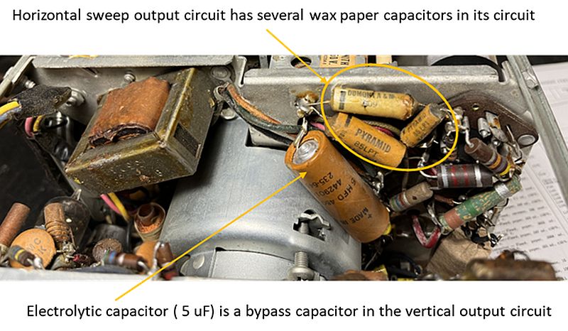
The horizontal sweep output circuit has several wax paper capacitors in its circuit as shown below. The electrolytic capacitor (5 uF) in the picture is a bypass
capacitor in the vertical output circuit.
After this re-capping effort, the horizontal frequency was quite high, near 17 kHz. I re-adjusted the horizontal sync control to lower the horizontal frequency to 15,750 Hz
and the television synchronized to the B&K TV Analyst signal. As shown below, the horizontal size appeared to be improved (with no manual adjustment). The focus appears to be improved
(with no manual adjustment). However, the picture pulls to the right at the top and the vertical size is not correct. Clearly, more restoration needs to be done.

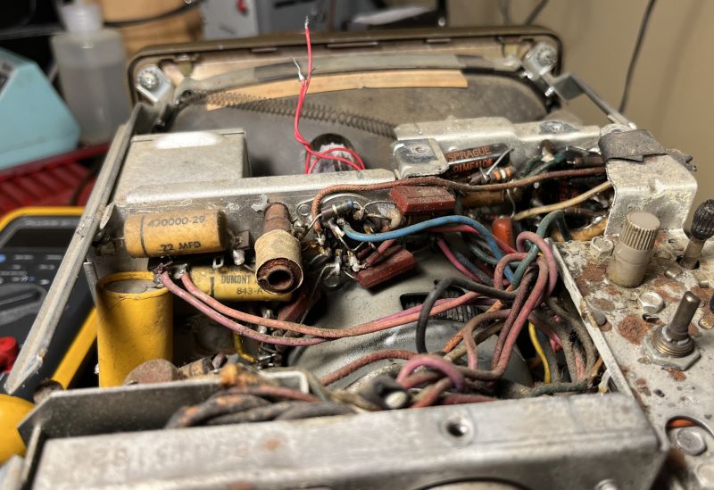
Next, I restored the vertical circuits. There are three wax paper capacitors and two "black beauty" oil-filled capacitors in the vertical output circuit as shown below. The
two "black beauty" oil-filled capacitors are apparently replacements from a previous repair.
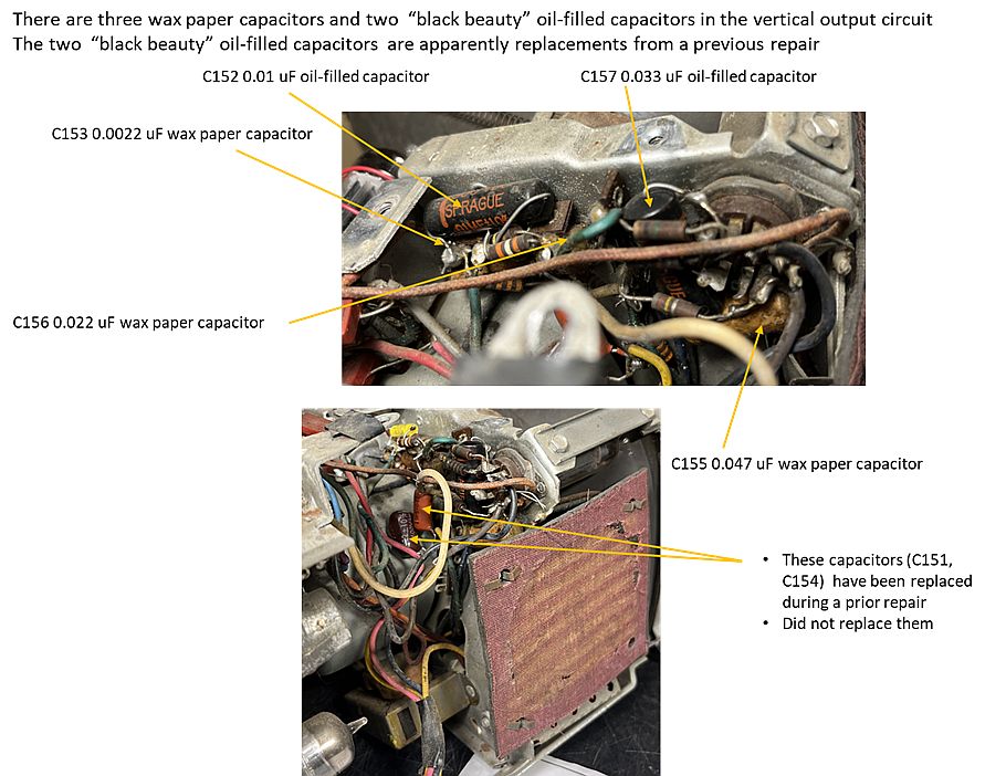
As shown below, I replaced three capacitors and one 33k-ohm resistor. The resistor broke when trying to remove C156, a 0.022 uF wax paper capacitor.
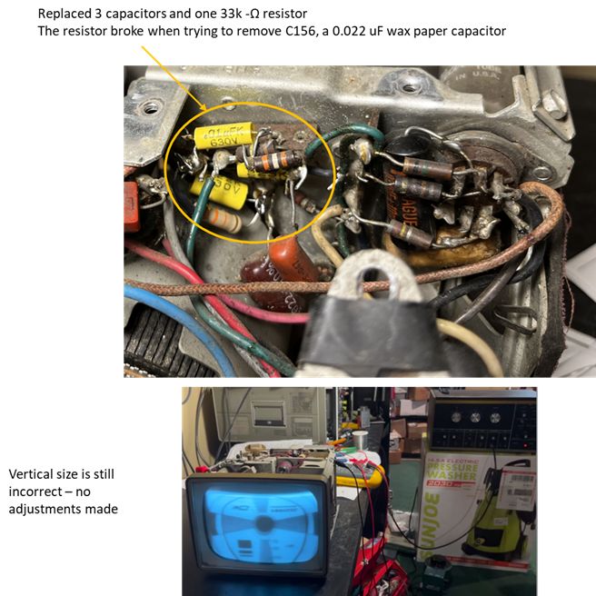
The vertical size is still incorrect with no adjustments made.
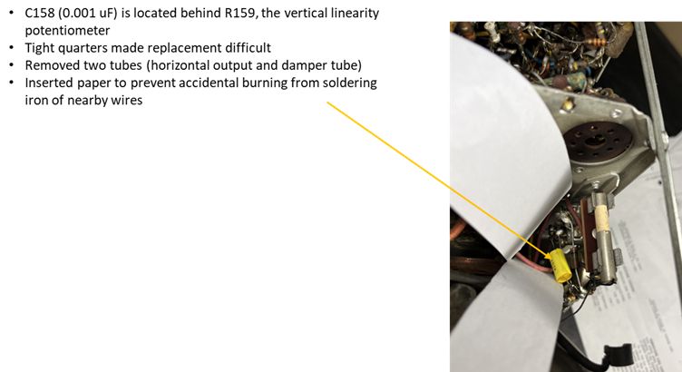
Replacing C158 was challenging becasue tight quarters made replacement difficult. Capacitor C158 (0.001 uF) is located behind R159, the vertical linearity potentiometer.
I removed two tubes (horizontal output and damper tube)and inserted paper to prevent accidental burning of nearby wires from the soldering iron as shown below.
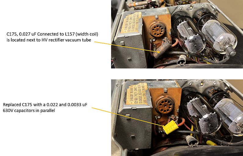
Capacitor C175, 0.027 uF, is connected to L157 (width coil) that is located next to HV rectifier vacuum tube a shown below. Not having a 0.25 uF capacitor on hand, I
replaced C175 with a 0.022 and a 0.0033 uF 630V capacitor in parallel.
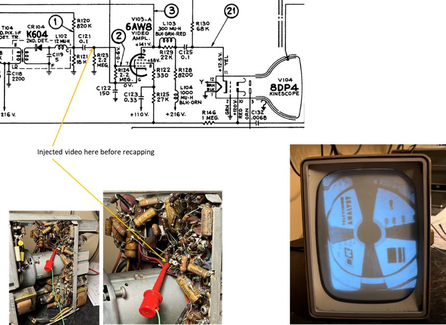
After this effort, the image is still not in focus and becomes distorted with adjustments to vertical height and linearity.
To further analyze the situation I injected video at the input to the 6AW8 video amplifier vacuum tube. Doing this produced an image in focus.
The vertical linearity and height still need some adjustment. As such, the out-of-focus image may be caused by the RF and/or IF stage out of alignment.
The picture shows the image using video injection.
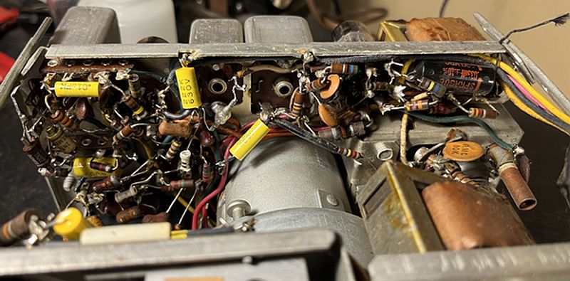
I continued to re-cap the video amplifier and sound circuits. The picture below shows the original video amplifier and sound FM ratio detector circuit.
The image below shows the re-capped video amplifier and FM sound ratio detector.
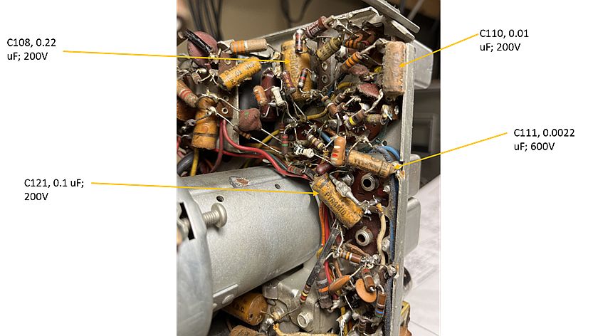
Next, I proceeded to replace capacitors in the first sync and sync output circuits as well as one capacitor in the screen supply of the video amplifier.
These capacitors are shown in the picture below.
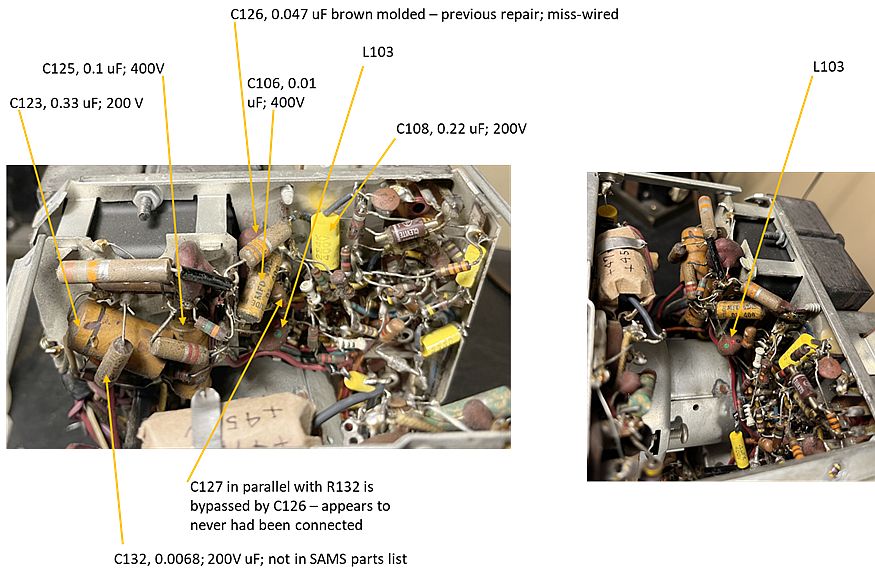
Capacitor C127 is in parallel with R132 but has been bypassed by C126; the C127/R132 combination appears to have never been connected. I believe that
C126, a 0.047 uF brown molded capacitor, was installed during a previous repair but miss-wired to bypass the C127/R132 combination. I did not change out
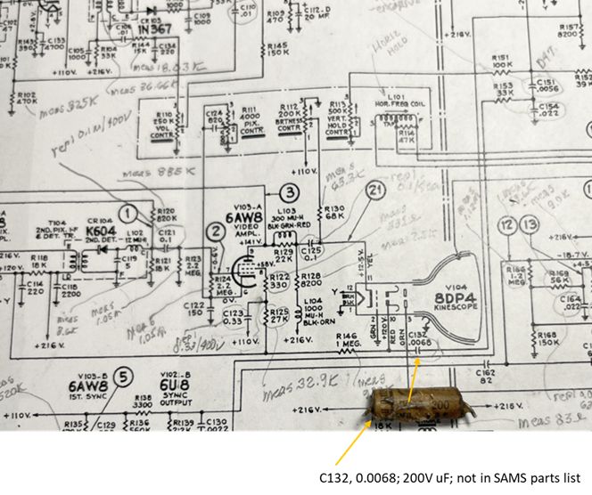
C126, nor did I wire it back in correctly per the schematic because the television does sync to a signal. The mis-wiring of C126 is shown in the schematic below.

Capacitor C132, a 0.0068; 200V uF capacitor is installed originally and is shown in the schematic but it is not listed in the SAMS Photofact parts list.
Capacitor C132 is shown below.
With the above replaced components, the focus is much improved; however, the focus appears sharper on the left side compared to the right side of the image. The
contrast is improved and the horizontal and vertical sizes are improved. There appears to be some horizontal pulling at the top of the image a shown below.
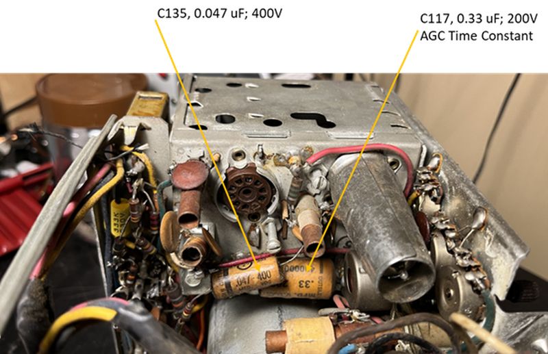
Next, I replaced C135 and C117, both located on the tuner. Capacitor C117 is the AGC time constant capacitor. These capacitors are shown below.
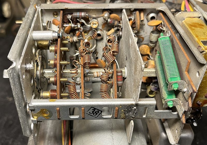
I opened up the tuner to see if the wafer switch contacts were corroded. There are no capacitors to change inside the tuner. The tuner was dusty inside and I blew out the dust
with my small air compressor and small brush. I de-oxed the channel selector wafer switch. Below is a picture of the inside of the tuner.
I also burnished the contacts to the antenna. Connections to the external rod-type antennas are made using wire springs that connect to the tuner contacts using the spring pressure.
I also burnished the two wire springs because they were quite corroded and thus added resistance to the antenna connections.
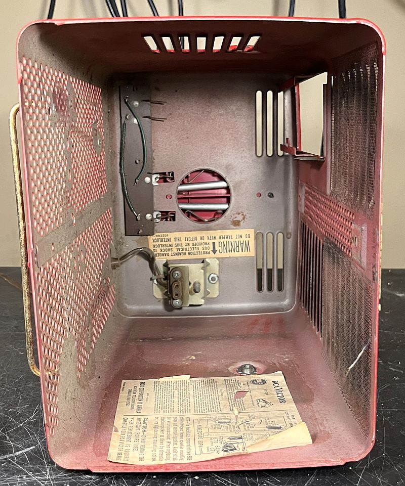
The picture below shows the interior of the cabinet. The two antenna connection wire springs are attached to a "circuit board" mounted to the rear of the cabinet. The wire springs for the tuner are
hard-wired on the "circuit board" to a pair of "receptacles" that connect to wire springs in the rod-type antenna assembly mounted to the rear of the cabinet. I burnished all of the wire
springs and their "receptacles" to ensure good electrical connections.
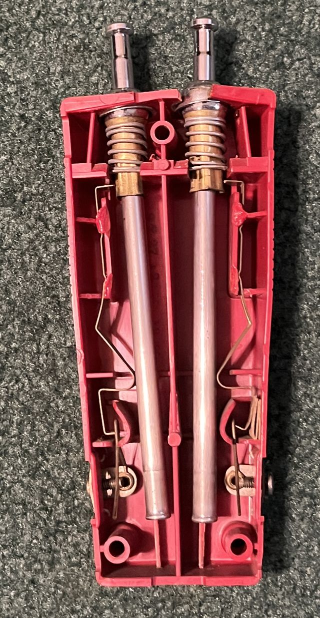
The picture below shows the rod-type assembly mounted to the rear of the cabinet. It is held in place by three screws.
I removed the rod-type assembly from the cabinet because one of the rod-type antennas showed no resistance from the rod to one of the springs. The inside of the
rod-type assembly is shown below. Both antenna rods are connected to their respective spring contact with a long spring wedged in a channel molded into the plastic housing.
One of those springs was not making contact with its wire spring. I placed cardboard in the channel between the long spring and the assembly sidewall to force the long spring to
make contact with the wire spring. The cardboard can be seen in the lower left in the picture below that shows the internals of the antenna assembly. The antenna assembly also
has screw terminals on both sides for connecting an outdoor antenna using 300-ohm twin lead.
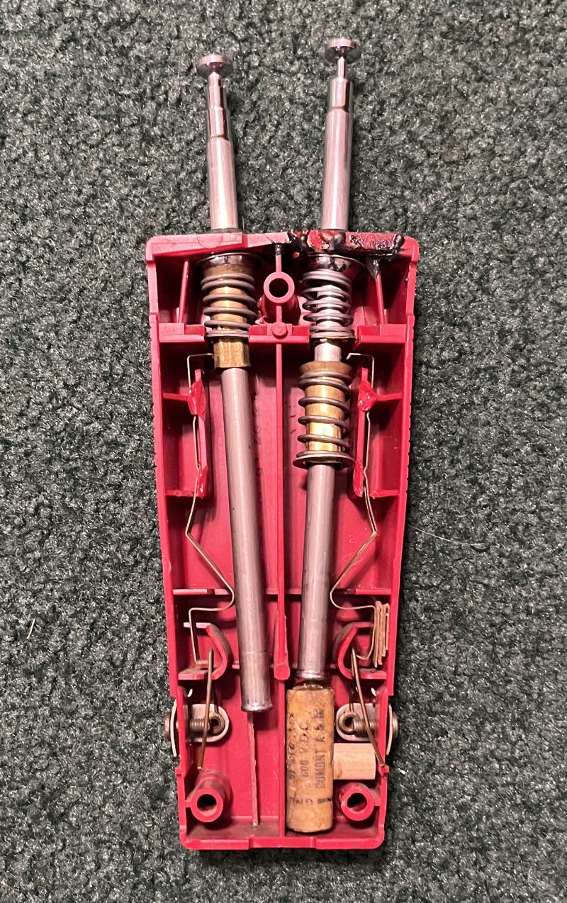
The plastic housing of the antenna assembly was cracked and a piece was missing when I received the television. The crack is associaed with the high-resistance rod antenna.
Later on when I extended the antenna, the plastic housing broke again. I epoxyed the broken piece back in place. I cut a small piece of woood to replace the missing section of plastic
and epoxyed it in place. There is a stiff compression spring around a brass tube that applies pressure to the ball sleeve that allows the rod antenna to rotate when fully extended.
This spring places a lot of pressure to the top of the plastic housing, and after many years, the plastic dries out and becomes somewhat brittle, leading to cracking.
I replaced the stiff compression spring with a compression spring that is not quite as stiff. I fabricated a brass washer to hold the spring in place. I inserted one of the wax paper capacitors
in the bottom of the assembly to prevent the antenna from being fully retracted into the assembly because it is difficult to pull out the one antenna when the rod antenna is full retracted.
And attempting to pull the rod antenna out from the retracted position places additional strain on the plastic housing. To preserve the original spring assembly, I placed it in the assembly and
placed the rod antenna through it. The new spring will not hold the rod antenna in place when fully extended, but it will allow the rod antenna to be functional when not fully extended and it
will preserve the original appearance. Below is a picture of the repaired antenna assembly.
In looking at the tuner, the metal shield that covers the RF amplifier vacuum tube is missing from this television. I did not replace this shield.
After all of the above restoration activities, the receiver sensitivity seemed weak. The picture image was not as sharp as it should be and the focus control did not signifcantly affect the image.
The sound was also weak and distorted. The above observations suggest either the tuner is not on frequency or the IF strip is out of adjustment. I decided to check the frequency of the
tuner local oscillator. Because the channel coils of the local oscillator are incrementally placed in series as the channel is decreased from Channel 13 to Channel 2, Channel 13 should be
checked first.
I used an HP 141T Spectrum Analyzer with a VHF plug-in. I used an HP 8640B Signal Generator to calibrate the spectrum analyzer. I removed the shield from the local oscillator vacuum tube and wrapped two loops of
wire around the local oscillator vacuum tube. I connected the loop to the spectrum analyzer. I clipped the output of signal generator to the insulated lead to the spectrum analyzer to inject the
frequency calibration signal. This approach allows both the LO and signal generator signals to be viewed simultaneously on the spectrum analyzer.
The frequency of the LO on Channel 13 measured several MHz higher than 257 MHz, that according to the SAMS Photofact is the local ocillator frequency for Channel 13. I adjusted the frequency
of the LO to overlay the frequency of the signal generator as seen on the spectrum analyzer, thus making the LO frequency equal to the signal generator set at 257 MHz.
I then changed the television to Channel 12. The LO frequency was correct at 251 MHz as seen on the spectrum analyzer when compared to the signal generator retuned to 251 MHz. I removed the loop
and replaced the shield on the LO vacuum tube. I inserted the loop slightly into the tuner through a hole in its side to recheck the frequency; the LO frequency did not change.
I then checked on-air reception on Channel 12 using my in-house analog television transmitter. I had to slightly adjust the fine tuning but the picture was sharp and the contrast was good.
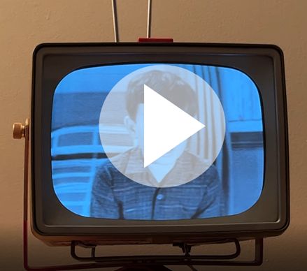
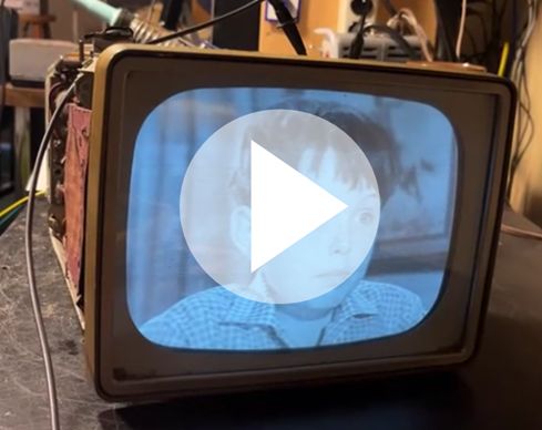
The sound is clearer, but adjustment of the 41.25 MHz sound boost coil on the tuner greatly improved the sound. Click on the image below to see a short video of the television receiving
an on-air analog program ("Leave It To Beaver") from my in-house analog television transmitter.
I did attempt to adjust the horizontal sinewave coil to acheive the horizontal waveform specified in the SAMS Photofact. The television will not maintain sync with the two peaks of equal amplitude.
However,sync can be maintained if the signal is synced before adjusting the sinewave coil for equal peaks, but sync will eventually be lost. To make the horizontal sync reliable, the first peak must
be lower as shown below (turn coil slug clockwise) as shown below.
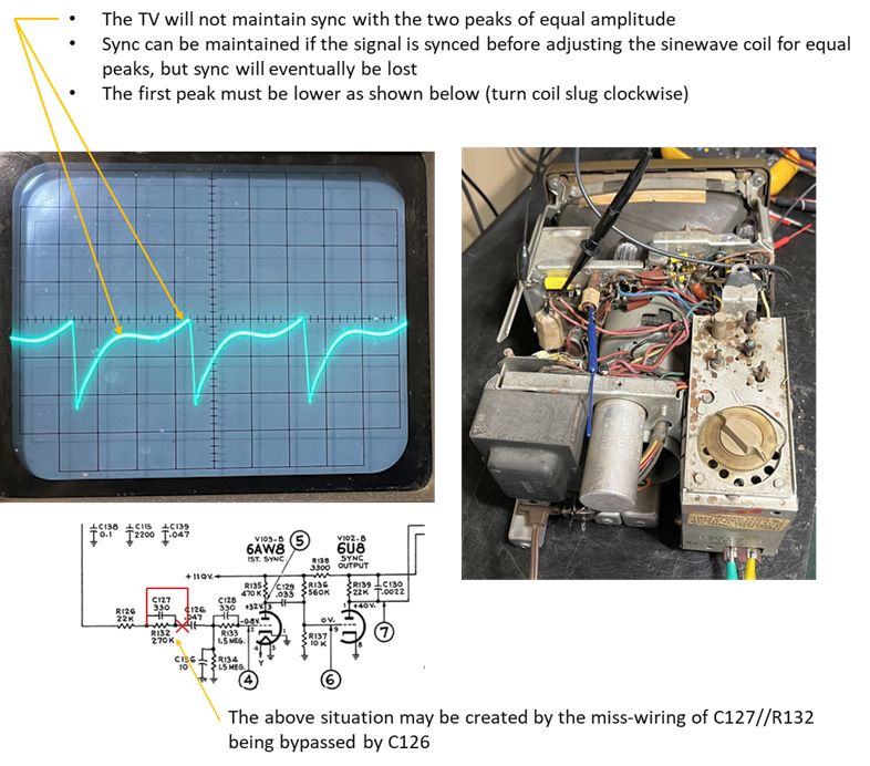
This situation may be caused by the mis-wiring of Capacitor C126 discussed above.
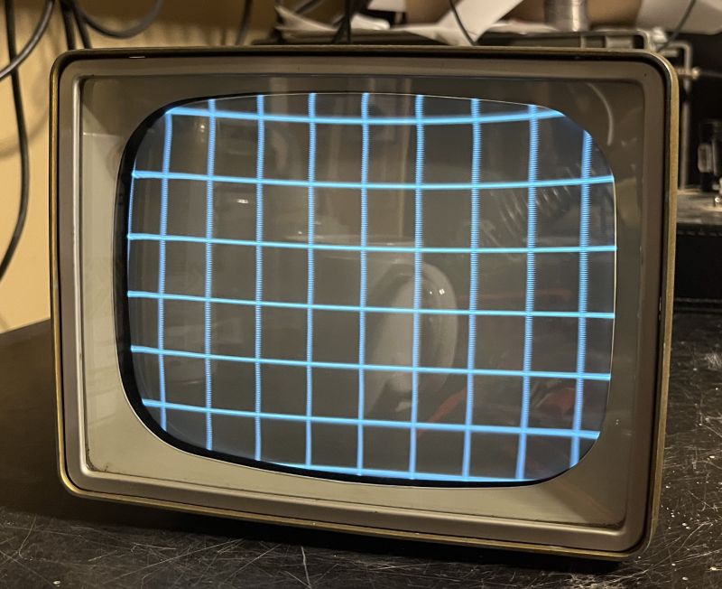
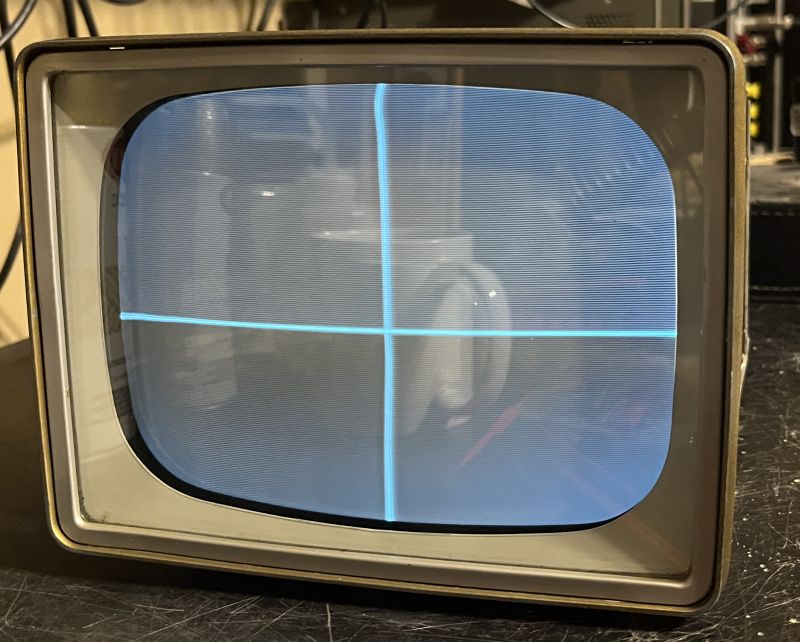
Further tests using different patterns produced by my B&K Model 1248 Digital Color Generator showed the linearity, centering, and width are acceptable. These results of these tests are shown below.
Fabricating a replacement stand required some design effort. The first task was to obtain or fabricate a thumbscrew receptacle compatable with an available brass knurled thrubscrew.
After extensive on-line search, I eventually decided to use a #1/4 20 "T-nut," available at the hardware store. The T-nut I used is shown below.
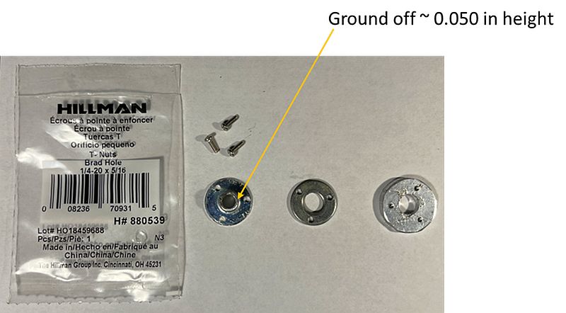
I fabricated a circular nut plate from 1/8-inch thick aluminum bar stock and drilled and tapped three 2-56 holes to align with the three small holes in the T-nut. The pcitures below show the
T-nut mounted to the exterior of the cabinet and the nut plate inside the cabinet.


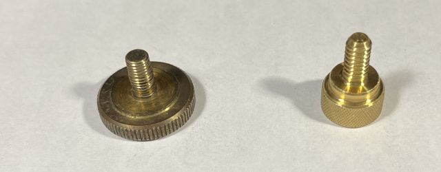
The orignal thumbscrew, of which have only one, has a #1/4 28 thread. The #1/4 20 T-nut is close in size to the original and I found a #1/4 20 x 1/2 inch knurled brass thumbscrew to use.
I could not find a brass knurled thumbscrew with a large head similar to the original. In the picture below, the original thumbscrew is shown on the left and the new thumbscrew
is shown on the right.
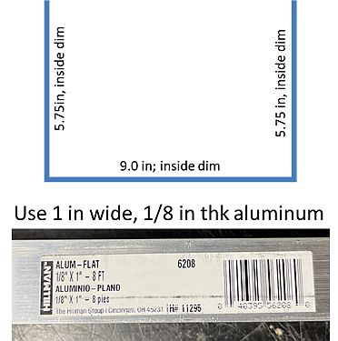
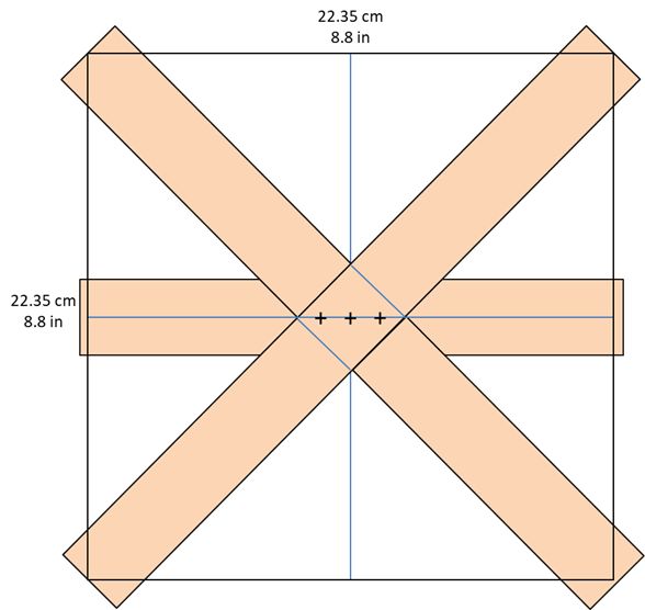
I fabricated the stand from scratch. Fortunately, there are pictures on the internet of the television on its stand. I scaled the pictures as best I could and designed the stand comprising
three pieces of bent aluminum bar stock. I used 1-inch wide, 1/8-inch thick aluminum bar stock to fabricate the stand. I did not replicate the tapered portions of the stand.
The picture below shows my dimensions for the "U bracket / yoke" for the stand.
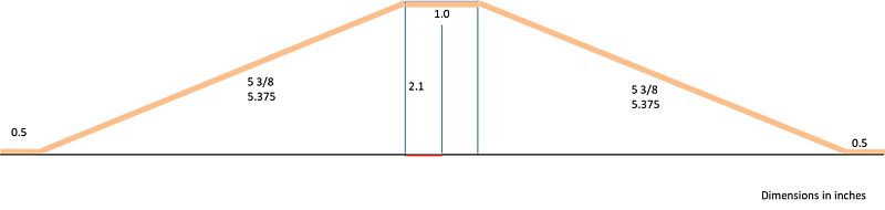
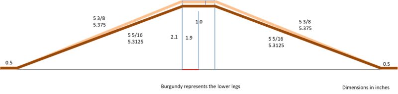
The pictures below show the dimensions for the two pairs of legs for the stand. Because one leg pair is mounted above the other, one leg pair is bent slightly different from the other.
Below is a picture of how the three pieces are assembled. The "+" symbols represent holes for three #4-40 screws to hold the assembly together.
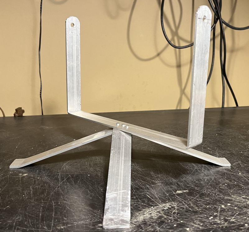
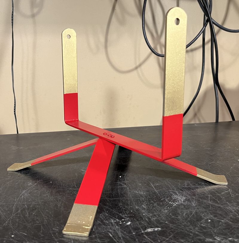
Below are pictures of the assembled stand before painting.
Below is a picture of the painted stand. The gold leaf and red color portions were estimated from pictures found on line.
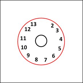
To replace the disentegrated control legends, I designed a new legend similar to the original and printed it on red printer paper. The circular legend for the twelve channels
was the most challenging to place the channel numbers in the exact locations. While the chassis was outside the cabinet, I marked the channel locations on white paper while
rotating the channel switch with its pointer knob through its twelve positions. After a couple of attempts, I was able to properly align the channel number with their positions.
The picture below shows the channel switch legend.
The channel number legend is intended to be viewed through the fine tuning knob that resides under the channel switch knob. Over the years, the fine tuning knob had yellowed
and had scratches underneath making it nearly opaque. I used Mothers Headlight Renewal Plastic Polish and Novus #2 Fine Scratch Remover to restore the fine tuning knob to
make it mostly transparent but with some yellowing present.
To properly place the channel legends and the knob legends, I scanned the bottom of the control assembly and flipped over the image and placed the legends next to the associated
holes in the scanned image. The picture below shows the legends placed next to their respective holes in the control assembly.
The picture below shows the control legends that are to be printed.
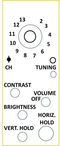
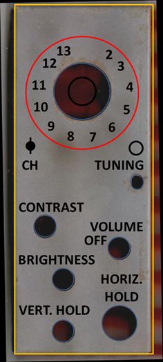
Below is a picture of the new control legends installed in the television. I printed the legends on red printer paper. The color does not exactly match the red cabinet.
I fabricated a new knob for the Brightness control from a piece of wood and painted it flat black.
Below are other pictures of the restored televsion.
Click on the image below to see a video of the restored television receiving an on-air analog program ("Leave It To Beaver") from my in-house analog television transmitter.