RCA BTE-15A FM Exciter
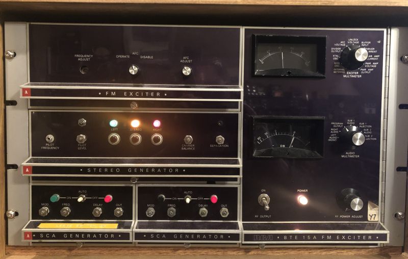
This page describes the RCA Model BTE-15A FM solid-state, direct-FM exciter manufactured by Mosley for RCA in the 1970s. The exciter shown above includes
the mainframe (including power supply and switching), the FM exciter, the BTS-1B stereo generator, and two BTX-1B SCA generators. The exciter components are contained
within a mainframe designed for mounting in a standard 19-inch rack. The entire unit is all solid state utilizing transistors and integrated circuits. The
FM exciter, stereo generator, and SCA generators are modulator and slide into the mainframe. The exciter provides an adjustable RF output up to 15 watts,
maximum, at any carrier frequency between 88 MHz and 108 MHz. Frequency control is accomplished by a quartz crystal contained within an oven for frequency stability.
The input impedance for the main channel and SCA audio is 600 ohms, balanced.
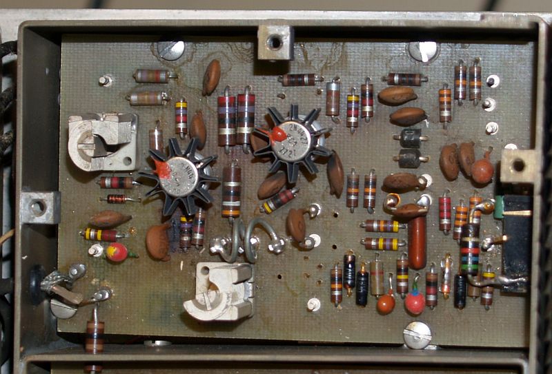
The modulated oscillator is a transistorized oscillator operating at the carrier frequency. Direct frequency modulation of the oscillator is accomplished by
varying the oscillator resonant circuit capacitance by applying audio modulation to variable-capacitance diodes (varicaps) in the resonant circuit. A sample of the
modulated oscillator output is divided down to approximately 6 kHz and is compared in a phase-locked loop to the crystal oscillator frequency (operating at
approximately 100 kHz) that is divided down to approximately 6 kHz. The picture below shows the modulated oscillator in the exciter with its cover removed.
At the time, this exciter exhibited excellent stereo performance and sounded good on the air. However, the exciter has been reported to break phase lock and
the carrier frequency "wander" off frequency.
The exciter is a single-channel unit. To change the carrier frequency, the quartz crystal contained within its oven must be changed, and the modulated oscillator
and the RF power amplifier must be retuned. Depending on the extent of the carrier frequency change, the resistors that establish the modulation level may need
to be changed. The exciter phase locked loop (PLL) reference quartz crystal and its oven (i.e. the channel element) is shown below.
It is a self-contained unit with an octal plug that plugs into a socket in the FM exciter module.
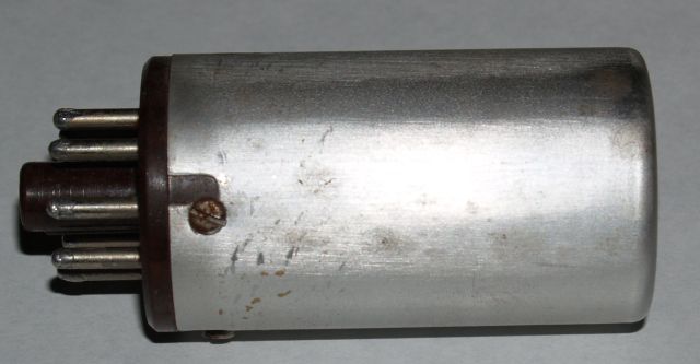
Depending on the carrier frequency, the crystal operates on a frequency between approximately 86 kHz and 105 kHz. As such, the quartz crystal is physically large. The
crystal frequency is computed as shown below.
Crystal frequency = (carrier frequency) / (1024)
Custom quartz crystals for specific frequencies are difficult to obtain. As such, to generate different carrier frequencies, another method for
frequency control is required. I designed a synthesized frequency source around the Etherkit Si5351A circuit card. The Si5351A integrated circuit is a programmable
CMOS clock generator and voltage-controlled crystal oscillator (VCXO) and is designed to replace crystal oscillators. The output of the Si5351A integrated circuit
is a square wave. The output of the Si5351A integrated circuit is amplified and input to the CA3028 integrated circuit that originally formed the crystal oscillator.
With this approach, the CA3028 functions as an amplifier rather than an oscillator. An Arduino circuit card is programmed to set the desired frequency of the Si5351A
integrated circuit upon startup. The carrier frequency can be changed by reprogramming the Arduino circuit card and retuning the modulated oscillator
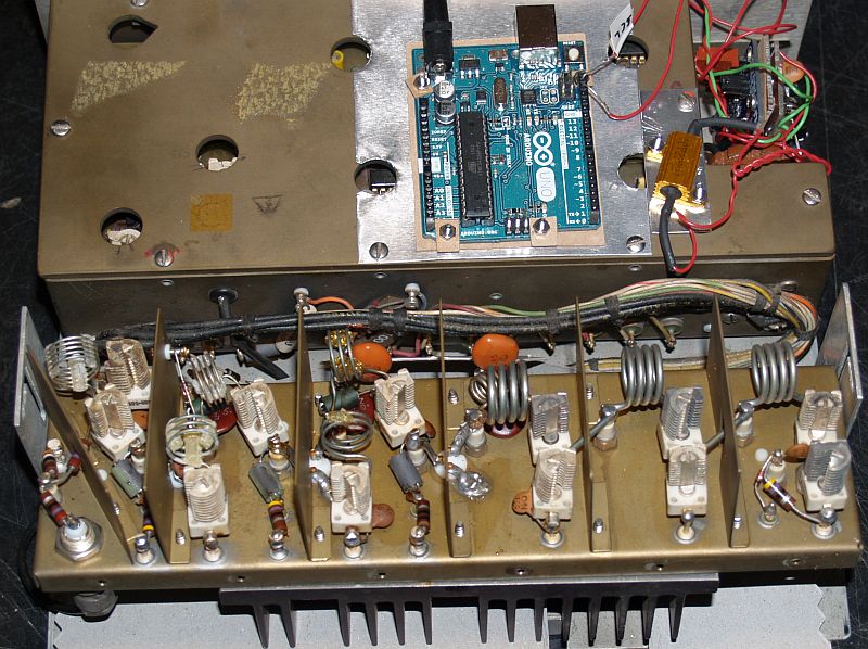
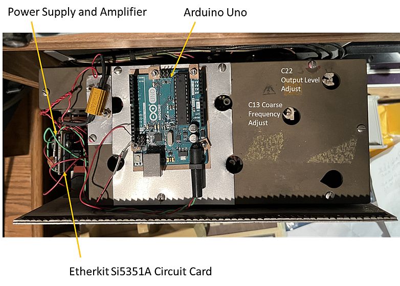
and the RF power amplifier. Below are pictures of the Etherkit Si5351A circuit card, the Arduino circuit card, the amplifier, and power supply installed in the exciter.
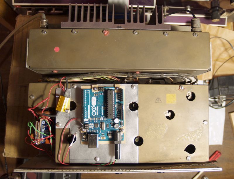
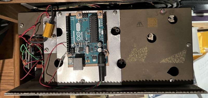
The Etherkit Si5351A circuit card, amplifier, and power supply are mounted on an octal plug such that it can be plugged into the exciter in place of the channel element.
Everything is powered from the exciter's +40-Volt supply available from the octal socket. Details are shown below.
The picture below shows the modified FM exciter, including the RF power amplifier with its cover removed.