I purchased the radio at a radio amateur convention (hamfest). The seller said the radio "hums", so that suggested to me the speaker was good but as a minimum, the power supply filter capacitors would require replacement as is typical. However, after a few hours of investigating, the most significant problems were an open 10k ohm resistor in the screen gridd power supply and a broken tube (6B7). The broken tube was not evident when I purchased it because it was in a tube shield and the tube was cleanly broken around the grid cap and stil held in place by the internal wires connected to the grid cap. In addition, to these problems, the grid coupling capacitor to the output tube would short upon application of power and therefore the outpu tube would slowly bring down the B+ power.
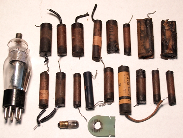
I replaced the resistor with a 10 Watt wirewound resistor and then I replaced all of the capacitors in the radio, including the power supply filter capacitors. Most of the capacitors were the wax paper type with tar-filled ends. Below is a picture of the replaced parts. You can see the broken tube on the left. Note all of the paper capacitors. I also replaced one of the #40 dial lamps and one of the green light reflectors that had a hole burned into it from the heat of the lamp. I made a replacement from a thin sheet of teflon.
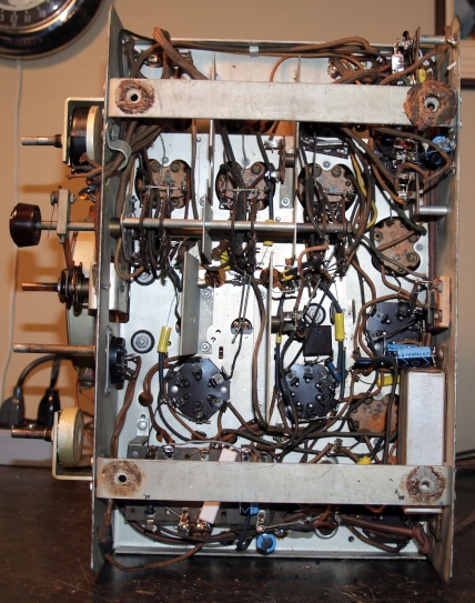
Below is a picture of underneath the chassis with the above components replaced.
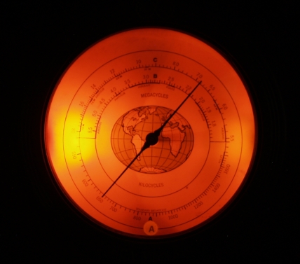
The radio did not need realignment after I made the repairs. The dial calibration is quite accurate on the Standard Broadcast band and not too far off on shortwave, so I did not attempt to calibrate the dial any further. The radio plays strong, is sensitive with a long wire antenna, and has loud volume with good tone.
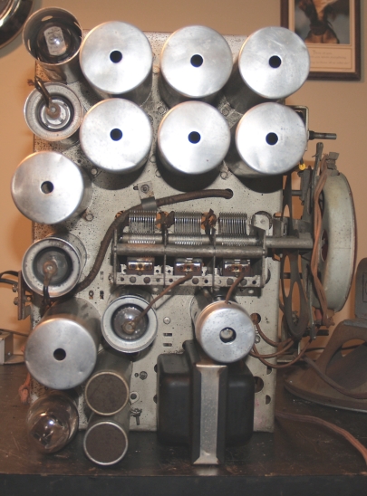
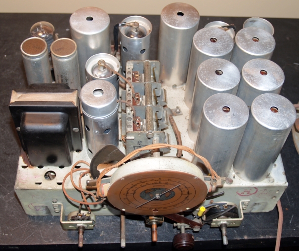
Below are pictures of the top of the chassis and the front of the chassis.
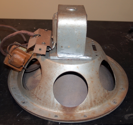
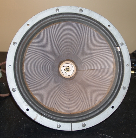
Below is a picture of the speaker. The speaker is hard-wired to the chassis. It does not have a plug or connector to separate the speaker from the chassis when removing them for repair. The output transformer attached to the speaker, the speaker field coil, and the speaker cone were all good and required no repair.
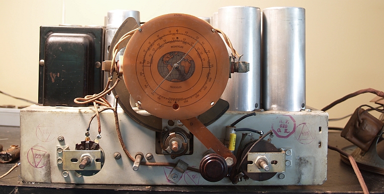
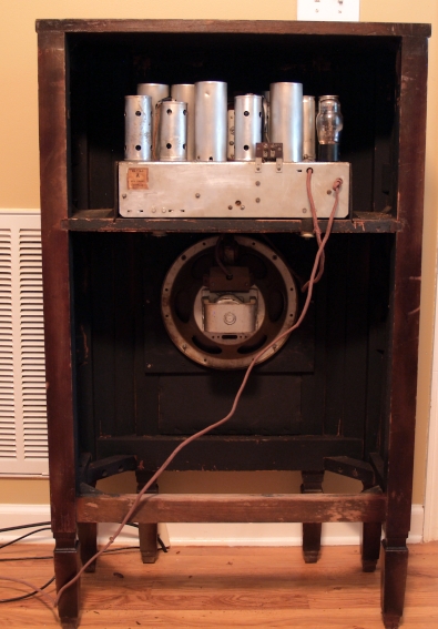
Below is a picture of the rear of the radio with the chassis and speaker installed.
The Riders electrical schematic for my radio is on page 6-35. The schematic for an apparent older version of the radio appears on page 5-65. The main difference I noted is the page 6-35 schematic shows a switch in the grid circuit of the #41 tube that shorts out a capacitor when operating on the two shortwave bands. My radio has that switch connection.