The circuit is a single conversion superheterodyne with an intermedate frequency of 175 kHz.
On the rear of the radio, there is a terminal strip where you can inject the audio from a magentic pick-up (phonograph). Thus you can use the audio section (the #27 detector tube and the two #45s) to amplify the phonograph audio.
The radio looked in good physical shape when I received it. However, this radio had a lot of electrical problems. I first checked all of the vacuum tubes and only 3 of the 8 tubes were good, and those were the two # 35 tubes and the #80 rectifier tube. The other five tubes were either very weak or had open filaments. The #80 rectifier tube would initially work, but it soon could not produce enough emission to power the radio. That confused me for a while because the B+ could not be maintained and I thought I had a short, but it was the tube giving up. It took me a while to figure that out because the tube tested good initially.
After a while, the volume control pot opened and the front end was dead. The front end RF amplifier and the local oscillator are connected to the volume control. The local oscillator did work initially but when the volume control pot opened, the local oscillator quit working. I opened up the pot and used silver paint (paint with silver in it) to short out the open. The picture below shows the repaired pot.
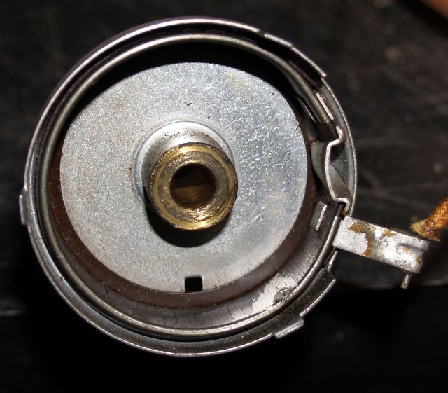
Below is the repaired pot with the wiper in place.
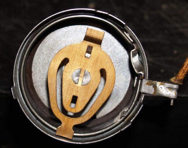
The pot seems to be OK now and the front end and local oscillator work properly.
After I fixed the pot, a coil winding in the RF stage opened (the front end went dead) and I had to install a substitute winding close to the large coil assembly underneath so it would couple into the next stage. The picture below shows the newly-mounted substitute coil winding. The substitute winding is an AM radio RF coil that I purchased.
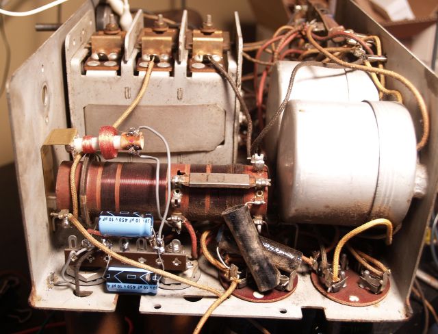
I rewired the power supply because one of the old filter capacitors was still in the circuit from a fix long ago and the set had a lot of hum. And the fix that someone did long ago did not wire the power circuit per the schematic. I have it wired correctly now and there is no hum. You can see the two blue electroylitic capacitors I added to the power supply in the picture above.
A long time ago, someone replaced one of the audio transformers - that fix is still good.
The on-off switch seems to have more resistance that it should but after I sprayed some degreaser into it, it seems to be OK.
The last problem was with intermittant connections with the tube socket of the #27 detector tube. I burnished the tube pins and the socket contacts. I also slightly bent the socket contacts.
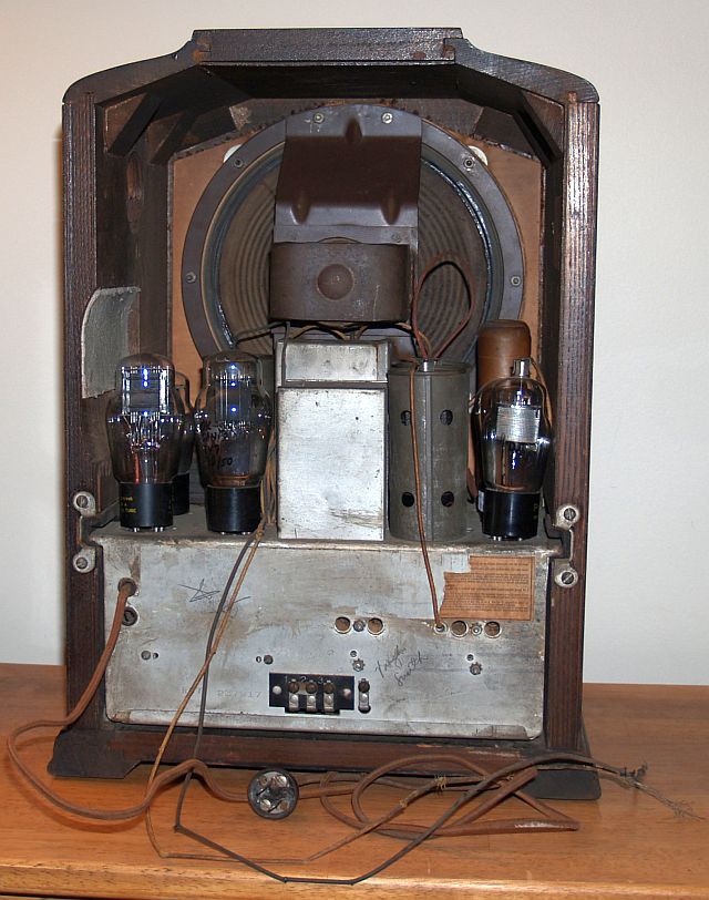
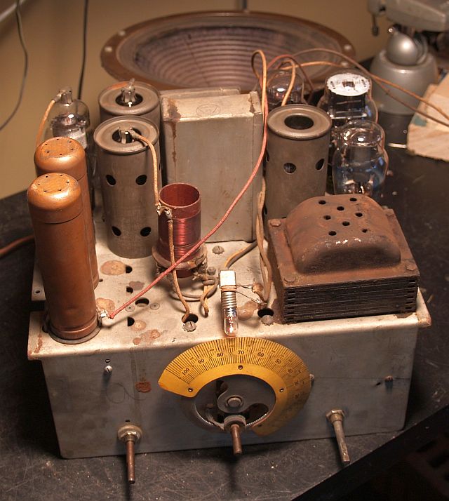
Below is picture of the top of the radio chassis.
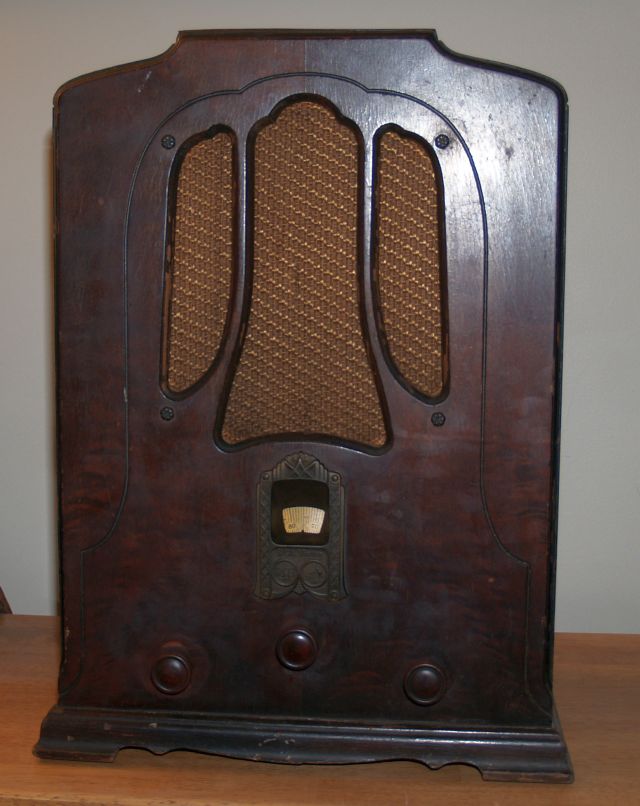
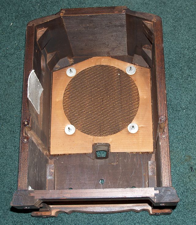
Below is a picure of the wood case without the radio chassis installed.
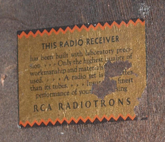
Inside the case there is a tag that instructs one to use only RCA Radiotrons for best performance. This tag is shown in the picture below. There was no model number anywhere on the chassis or case.
Below is a picture of the rear of the radio.