 >
>The picture above is of a late 1950's/early 1960's 3-inch oscilloscope, RCA Model WO-33A, intended to be used to trouble-shoot and signal trace all sections of both analog black-and-white and color-TV receivers. The voltage-calibrating facilities, wide band-pass, and high-impedance input characteristics made possible observations and measurements of color-burst signals and other critical high-frequency waveshapes in circuits that were sensitive to loading effects.
The oscilloscope is a vacuum tube device designed for "on-location" and service-shop use in servicing color and black-and-white television receivers, Hi-Fi equipment, PA and sound reenforcing systems, broadcast station and remote equipment,communications and industrial electronic equipment.
An unusual feature of the WO-33A is the Vertical Input Attenuator that automatically switches the amplifier from Wide Band to Narrow Band when in the three highest gain positions.
The vertical amplifier has enough sensitivity to provide a useful display of signals from low-level microphones, phonopickups and other weak signals found in radio/TV receivers, audio amplifiers, etc.
A voltage-calibrated, frequency-compensated vertical-input attenuator, an internal calibrating-voltage source, and a graph screen scaled directly in volts make it possible to use the WO-33A as a visual voltmeter.
The method of calibrating the graph screen provides for scaling voltages directly from the screen. A calibrating voltage is automatically applied to the vertical amplifier when the bandwidth control is set to the calibration position. This switch also disconnects internally the input and attenuator circuits, making it unnecessary to remove leads and probes from the external circuit under test. The calibration voltage is the internal 6.3 Vac 60-Hz filament voltage for the vacuum tubes in the scope.
The horizontal sweep-frequency control is continuously adjustable from 15 cps to 75 Kc.
The oscilloscope was available already assembled or available in kit form [model WO-33A(K)].
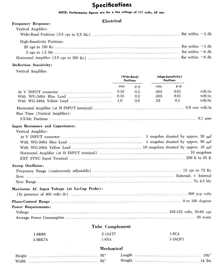
Below are the specifications of the oscilloscope.
Although my example of the oscilloscope shows its age, it does work. The front panel is significantly scratched and most of the plastic covers for the controls are missing.
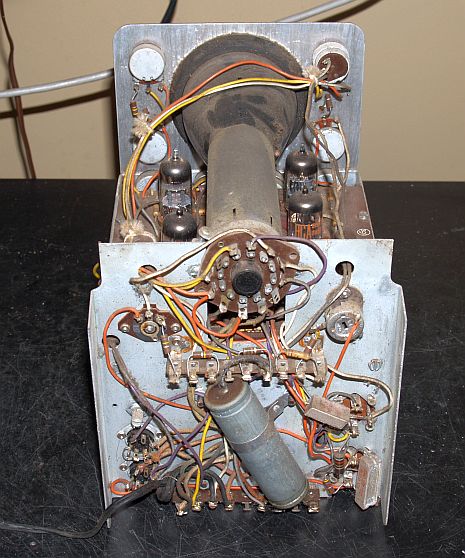
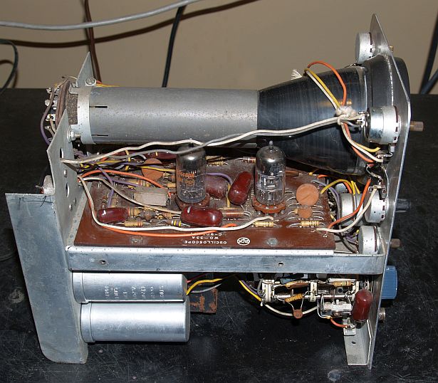
Below are pictures internal to the oscilloscope when I received it showing that it was extremely dusty.


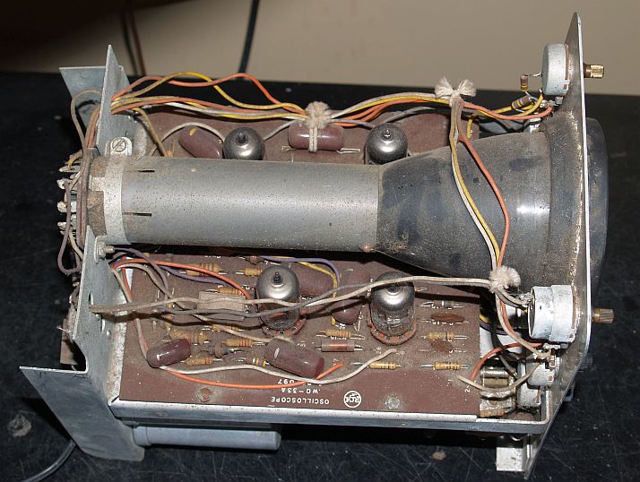
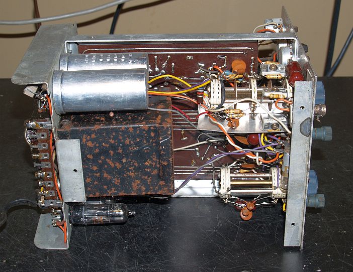
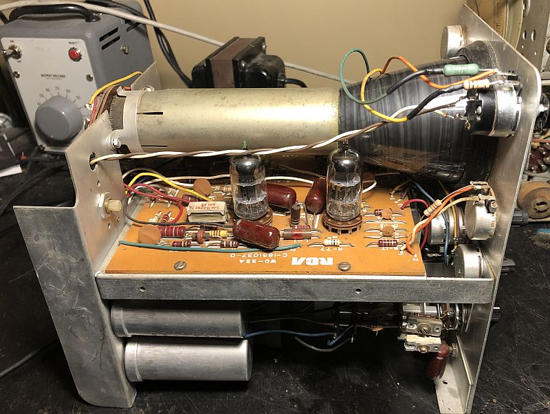
Below is an internal picture after I cleaned the circuit boards.
Below is a picture showing the internal calibration signal on the screen.
Below is a picture of the front of the oscilloscope.

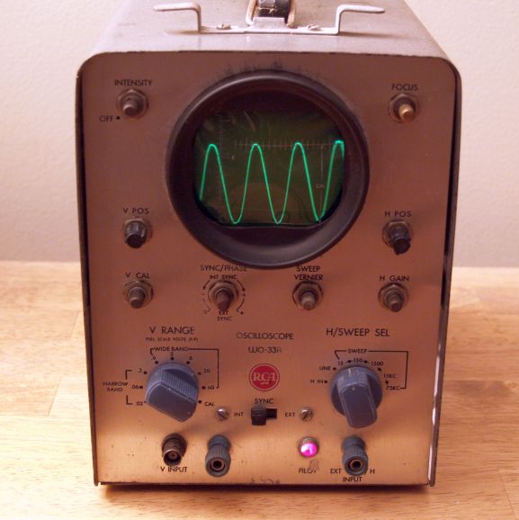
Later, I acquired a second copy of this oscilloscpoe shown below. This example has the plastic covers on all of the knobs. This example is a later version as it has the newer RCA letter-only logo as compared to my other example that has the older round emblem.
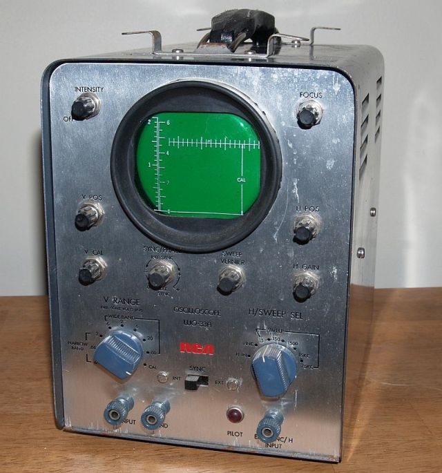

And later, I acquired a third copy of this oscilloscpoe shown below. This example is enclosed in a sky blue cabinet and has the plastic covers on all of the knobs except the Intensity/ON-OFF Switch, that was missing when I acquired the scpoe. Because of the cabinet color, I believe this may be the newest version of this scope. For the vertical signal input, this version scope uses a miniature microphone connector made by Electrocraft that is difficult or impossible to obtain.

The intensity control is a 75 k-ohm potentiometer with an integral single pole single throw switch. I could not find a one with that resistance value, but I did find one that was 47 k-ohm. I installed it and also installed two resistors in series on either side to make the total resistance equal 75 k-ohm. The new control can be seen in the upper right of the picture.
This approach works, but the adjustment range is limited, but not so much that the scpoe is not usable. The trace can be turned mostly off (it is very faint) and turned up to produce a bright trace on the screen. After I replaced the control and cleaned it up, the scope works well. Below is a picture of the scope with its calibration signal on. I took this picture with my iPhone and the phone could not completely capture the slow scan of the scope and thus part of the trace appears missing.

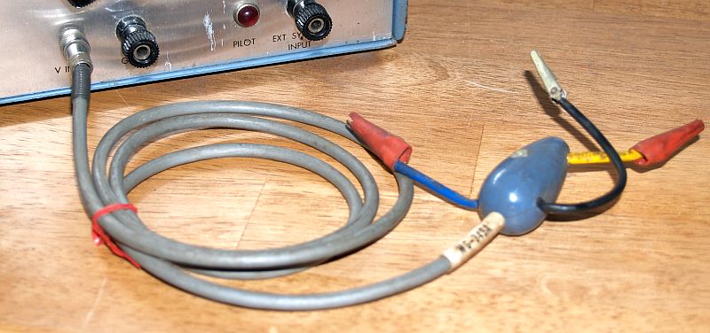
I also have the WG-349A Direct/Low-Capacitance Probe for the blue oscilloscpoe. This single-unit probe is equipped with two clips from the probe housing which permits using the probe for direct measurements or for connecting a built-in high-impedance network in series with the test point and the probe cable. When the yellow lead is used, the input capacitance of the cable and scope is reduced to 10 pF and the input resistance is raised to 10 megohms. These high-impedance characteristics permit use of the WO-33A in high-impedance circuits, such as those found in TV sync-separator and video-amplifier stages, which would not operate properly if loaded down by a conventional scope probe and cable. The probe is shown below.

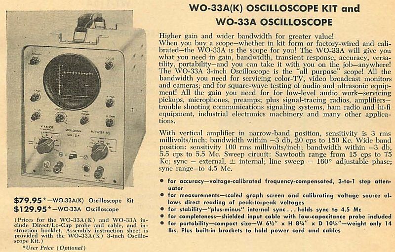
Below is an advertisement for the oscilloscope from circa 1960.
Below is a portion from an RCA test equipment catalog showing the oscilloscope.

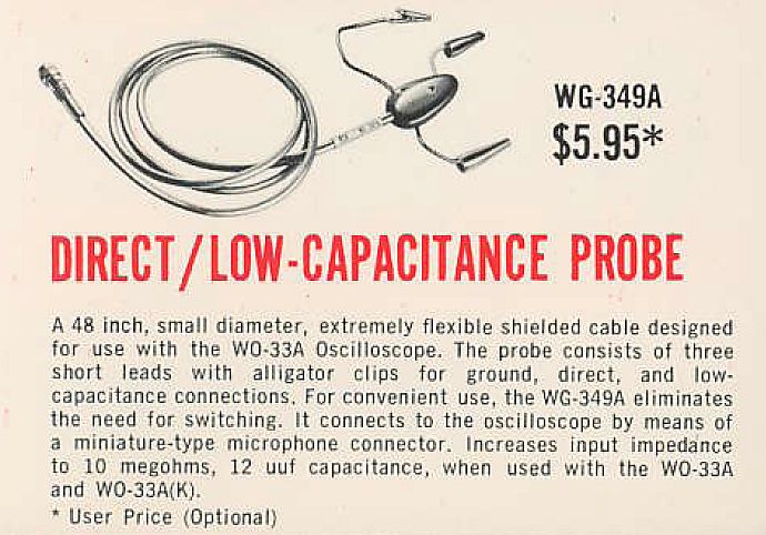
Below is a portion from an RCA test equipment catalog showing the WG-349A probe.
All three oscilloscopes are shown below in with the the oldest version on the left with the old RCA emblem and what I believe is the newest version on right.
