Below is a closeup of the face of the instrument.
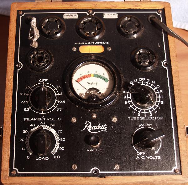
The instrument is turned on with the pointer knob on the lower right. Turning the knob clockwise turns the instrument on and you are to rotate the knob until the shadow line on the shadow meter aligns with the line marked on the meter face. The shadow meter can be seen in the photo above as the illuminated oval in the top center of the panel. In the photo, the instrument has been turned on and the shadow line is just to the left of the mark. According to the theory of operation that came with the meter, aligning the marks, ensures the metering circuit is supplied with exactly 30 Vac. The voltage is critical to ensure accurate tube emission measurements.
Other controls include:
Set the filament voltage(center left)(adjustable for 1.5, 2, 2.5, 3.3, 5, 6.3, 7.5, 12.6,a nd 25 V),
Selects the proper configuration of the tube and tests for shorts,
Selects the proper load for the tube for emission tests.
When measureing emission, you press the button in the lower center, called "Value", and observe the meter. The meter will indicate good (green), bad (red), or unknown (the narrow yellow band).
Below is a picture of the inside of the instrument.
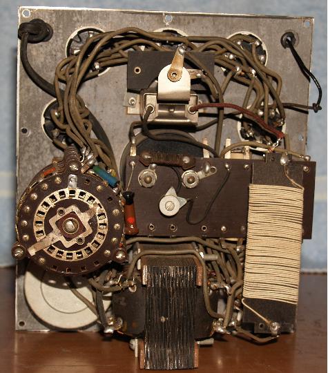
The circuit is simple as you can see. Many of the resistors have to be precision so they are made with wire. There are some carbon "doggy-bone" resistors. There is a rectifier in the short measuring circuit. The instructions say it is of the copper oxide type.
The instructions have settings for 1930'3 and earlier tubes such as:
'00A
'01A
'10
'12A
24
26
30
43
'71A
80
25Z5
And many others.
The tester will also test tubes with a grid cap. Note the clamp in the upper right of the 2nd photo. That clamp attached to the grid cap of the tube under test. So the tube tester will test tubes used in many of the antique radios that I have. The tester appears to work fine.