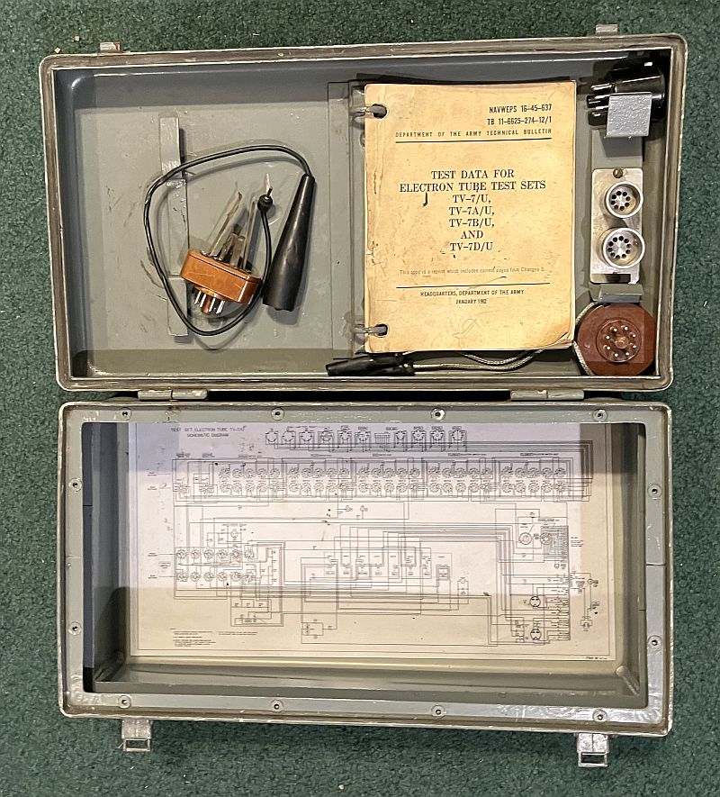
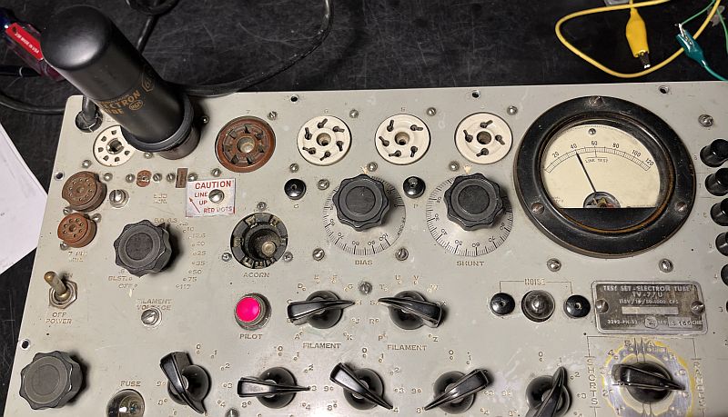
This is a TV-7/U vacuum tube tester originally used by the US military. The test set employs the dynamic mutual conductance method to test amplifier tubes. The test set also tests tubes for shorts, noise, and gas. The quality of rectifier tubes is checked by measuring the dc emission of the tube under static conditions. Cold cathode-type tubes are tested similar to diode detectors and vacuum tube rectifiers except a higher voltage is applied to the tube. Below is a picture of the front panel.
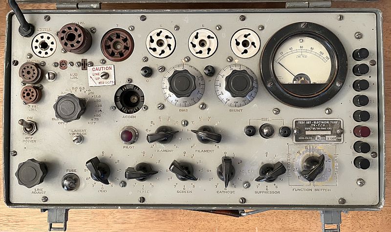
This example is the first version in this series of electron tube test sets. Versions TV-7A/U, TV-7B/U, TV-7C/U, and TV-7D/U followed this example. The TV-7D/U includes potentiometers to calibrate the unit. To calibrate the TV-7/U unit, one has to either parallel resistors to existing resistors or replace existing resistors.
Although my example looks a little rough, it does work after I repaired it. The unit was sold to me as working, but the meter did not move when the button was pressed to measure mutual conductance. The 5Y3 screen and bias rectifier tube and the 83 mercury vapor plate rectifier tube both tested good on my other tube testers. Troubleshooting revealed that resistor R111, a wire resistor wound on a bobbin, was open. An ohmmeter measuring across the resistor essentially read the resistance of the test set meter, approximately 2.5k ohms (The measurement included the resistance of the meter plus the other resistors in the bridge measuring circuit). I soldered a 110 ohm resistor in parallel with R111 to achieve the schematic value near to 109 ohms.
With the bridge circuit open-circuit, the resistances of the four resistors measured:
The bridge resistors, R115 and R113 are matched within 1.1 ohms. It is critical that these resistors are matched. R118 and R111 are both higher than 109 ohms, but almost identical in resistance. With the circuit closed, the resistors in circuit measured:
I went through the calibration procedures described in the US Army Technical Manual TM11-6625-274-35 dated 30 June 1960. The bias voltage test, plate voltage and line adjust circuit test, and initial screen voltage test all resulted in measured values quite close to that specified in the manual. However, when pressing the mutual conductance and diode button simultaneously in the second screen voltage test, the voltage measured 64 volts instead of 56 volts. Adjusting Clamp B on resistor R130 fixed that problem.
The short circuits test all passed. However, the simulated tube test described in the manual using a 50-volt ac source from a variable transformer yielded a reading of 48 (should read 40) on the meter when the mutual conductance button was pressed in Function Switch settings B, D, and E. A voltage of 42.3 Vac will read 40 on the test meter. Paralleling a 390-ohm resistor with R113 as described in the manual will make the meter read 40, but that modification will cause the 6L6 tube test to read 1/2 of what it should read. Therefore, I did not permanently make the modification.
When running the mutual transconductance conductance test using a known good 6L6 tube, the meter read negative and the needle moved to the left instead of moving to the right. The meter would read forward when in Ranges B and C, but in Ranges D and E, the meter read reverse or negative. Furhter investigation revealed that resistor R120, an 800-ohm wire resistor wound on a bobbin, one of three resistors in the grid modulation voltage divider network, was open. As such, when in Ranges D and E, the modulaion input was left floating because of the open resistor. I relpaced the open resistor with a series combination of a 330-ohm resistor and 470-ohm resistor and then checked the modulation rms signal levels. Now the measured rms voltages with a bias setting of zero are:
Range B: 4.81 VAC
Range C: 4.81 VAC
Range D: 0.978 VAC
Range E: 0.49 VAC
The above measurements are quite close to what they should be.
With this repair, the mutual conductance test of the known good 6L6 tube reads 40. On Range D (the range used for the 6L6 mutual transconductance test on a TV-7U) a reading of 40 is equivalent to 5,000 micromhos, that is typical for that tube operating as a Class A1 triode amplifier. The picture below shows that mutual conductance test on this TV-7U tube tester.
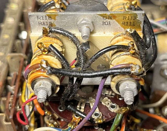
Below is a picture of resistor R11 before repair.
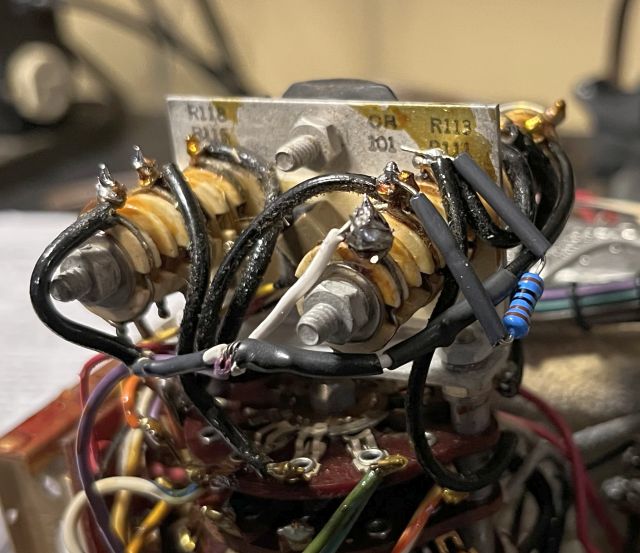
Below is a picture of R111 after repair and experimentation.
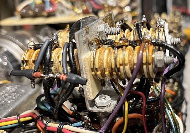
Below is a picture of R120 after repair.
Below are pictures of the chassis.
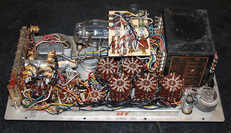
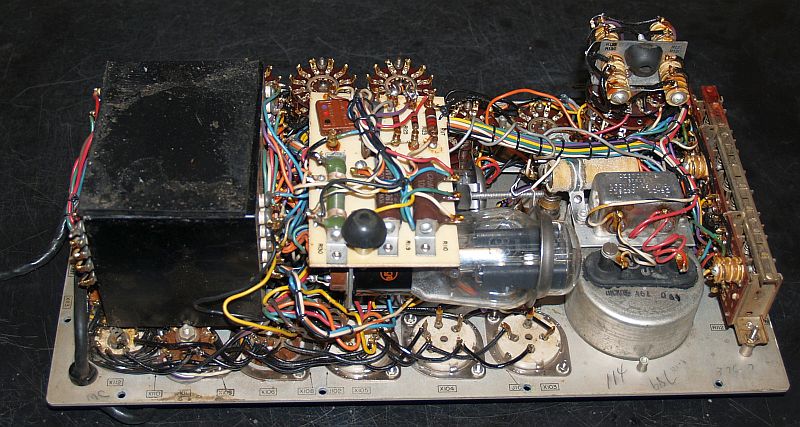
I noticed there are a couple of wires with their insulation crushed. These wires apparently were crushed when reinstalling the chassis in the cabinet during previous repiars. I tied the off the wires such that would not happen again.
Below is a picuture of inside the cabinet with the chassis removed.