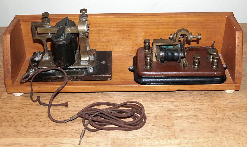
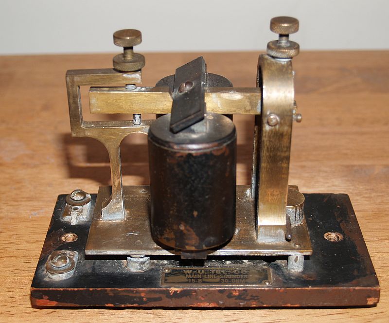
The sounder, shown above, is a Western Union Telegraph Company "Main Line Sounder," Model 15-B with a 30-ohm resistance. Note the name tag on the wood base. Because it is a main line sounder, it can be connected to the main telegpraph line without using a Morse Relay. I understand main line sounders typically have a resistance of 30 to 200 ohms. Below is a view of the other side of the sounder.
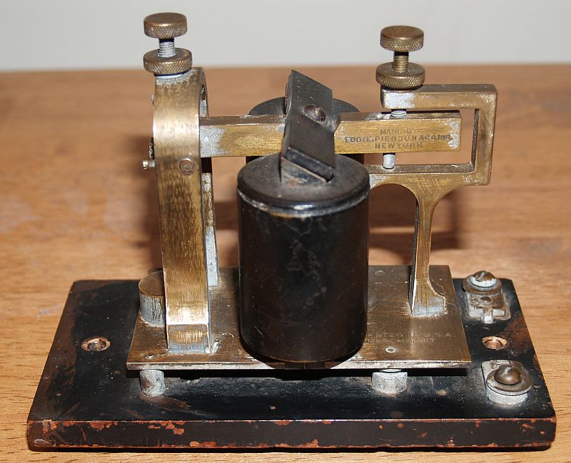
This sounder was manufactured by Foote and Pierson Company of New York as can be seen on the lever arm. To the right of the coils on the bottom brass place you can see a patent date of 1917. The sounder has two adjustments one for the spring tension and the other to adjust the click/clack. Below is a bottom view of the sounder.
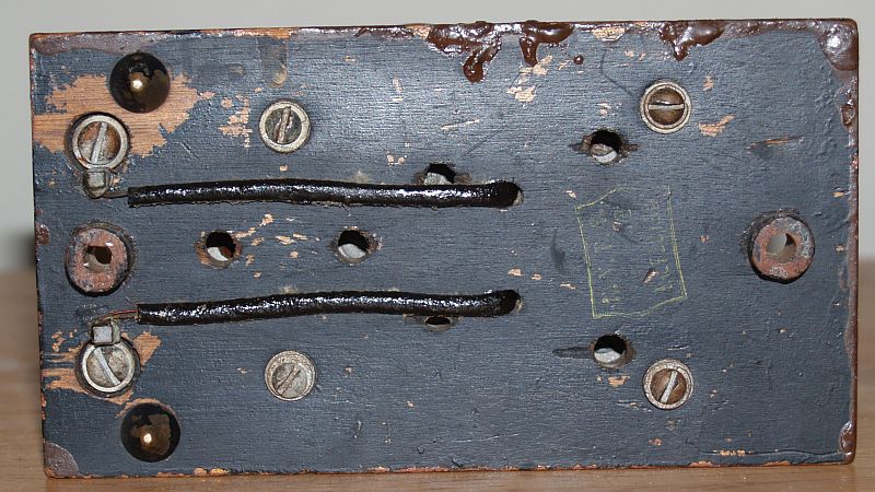
On the bottom right-hand side, you can see an inspection stamp in white ink. The stamp has the intitals N.Y.R.S.that stand for New York Repair Shop and the word "inspected." The Morse Relay is discussed below.
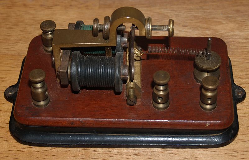
The Morse Relay, shown above, has no manufacturer markings.On the bottom of the relay, "200 ohms" is etched in the wood. However, someone has rewound the two coils of this example such that the resistance is much less than 200 ohms.This relay does work, however, but not with a typical main line voltage. The relay is intended to be quite sensitive to the presence of a voltage. The relay armature (the part that moves) is vertical and held in the far right position (as shown above) by a weak spring. The spring is attached to a capstan so that it can be adjusted. The armature also has two adjustment screws at its pivot points.
The goose neck brass part above the armature contains the stationary relay contact. In the non-energized position, shown above, the armature is resting against an insulated "contact" such that no electrical contact between the armature and the goose neck is made. When the relay is energized, the armature swings to the left and makes electrical contact with the left-hand contact. The two contacts can be adjusted in and out for best performance. One does not want the armature to come in contact with the coil core as it will magnetize the armature and stick.Therefore, the adjustment for the energized mode is somewhat critical. One must adjust the contacts for best performance considering the main line voltage and the best sound from the sounder in the local telegraph office in which the sounder and relay are located.
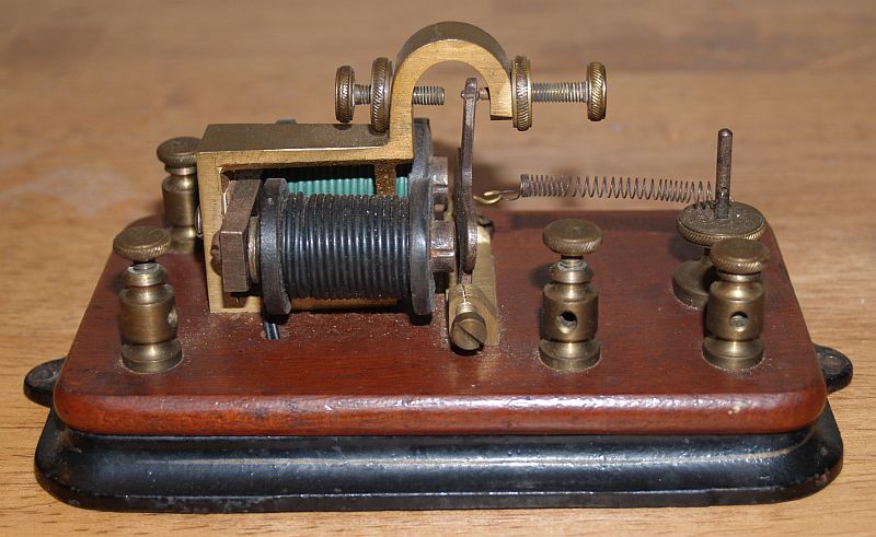
The two contact posts on the right-hand side connect to the armature and goose neck, respectively. The two contact posts on the left-hand side connect to the coils. The two coils are connected in series.
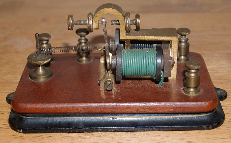
The pictures below are other images of the Morse Relay.
These two telegraph apparatus do work. I used a 9-Volt "wall wart" and the code key below to key the sounder and relay.
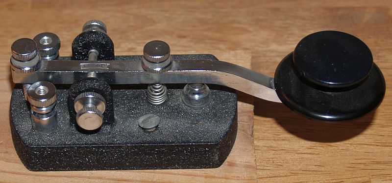
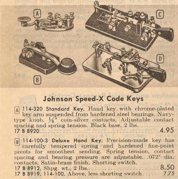
I purchased the straight code key above around 1968 from Allied Radio. It has the Navy-style knob and was considered a "heavy duty" key. Engraved on the key arm is "Speed-X." The key was manufactured by E.F Johnson Co. This code key would typically be use for radio Morse code (CW) transmissions although there really is not much difference in this one and one used for ground telegraphs. Below is an image from the 1968 Allied Radio (Chicago) catalog showing the key (item "B" in the image). Note the key is referred to as a "deluxe hand key" and was sold in two versions - with and without a shorting switch. Mine does not have the shorting switch and sold for $7.75.
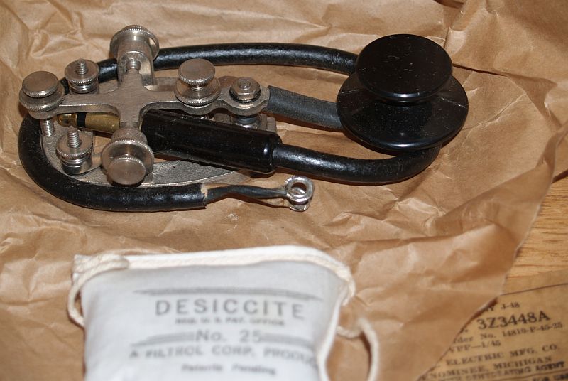
I also have another code key that my uncle gave me. The key is shown below. This is a J-48 military-style standard code key used for radio transmission. Note that I have the original packaging for this key, including the original sealed package with its dessicant.
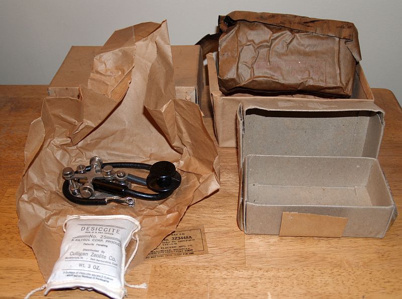
The model number of the code key is J-48 "3Z3448A." It was manufactured by Signal Electric Company of Menominee, Michigan. Below is a close up view of the code key.
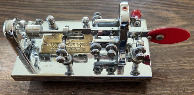
I purchased a 1960 vintage Vibroplex Original Deluxe key at a hamfest (amateur radio convention). The key as received is shown below.
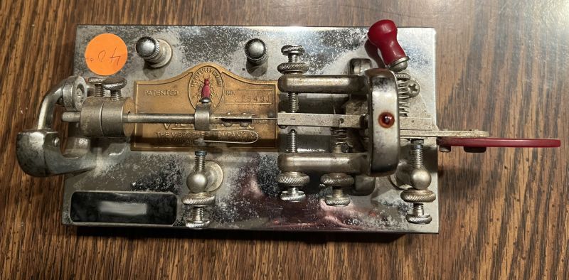
The key has several places where the chrome was spotted. The previous owner had placed in the corner a label with his radio amateur call letters. Below is a picture of the key after removing the call letter label and cleaning the chrome with Brasso.
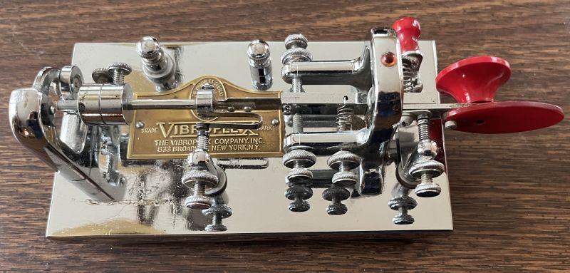
The key was also missing the red finger piece. I ordered both a red finger piece and a red oval thumb piece from Vibropex in Knoxville, TN. Vibroplex advised me the red plastic had changed over the years and as such, if I wanted both pieces to match, I should order both. Below is a picture of the key with only the new finger piece installed. The original oval thumb piece was left as is. The difference in color is evident. The original red thumb piece is translucent; however, the new red finger piece is solid red.
I replaced both pieces to have a uniform appearance of the finger pieces. The red piece on the shorting switch is the original translucent red. Its difference does not detract from the overall appearance of the key. This configuration is shown below.
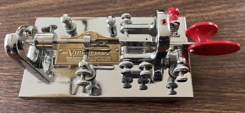
The key is in working order and looks almost brand new. According the serial number, the key was manufactured in 1960.
I have a table-mount telegraph sounder box manufactured by Western Electric shown below.
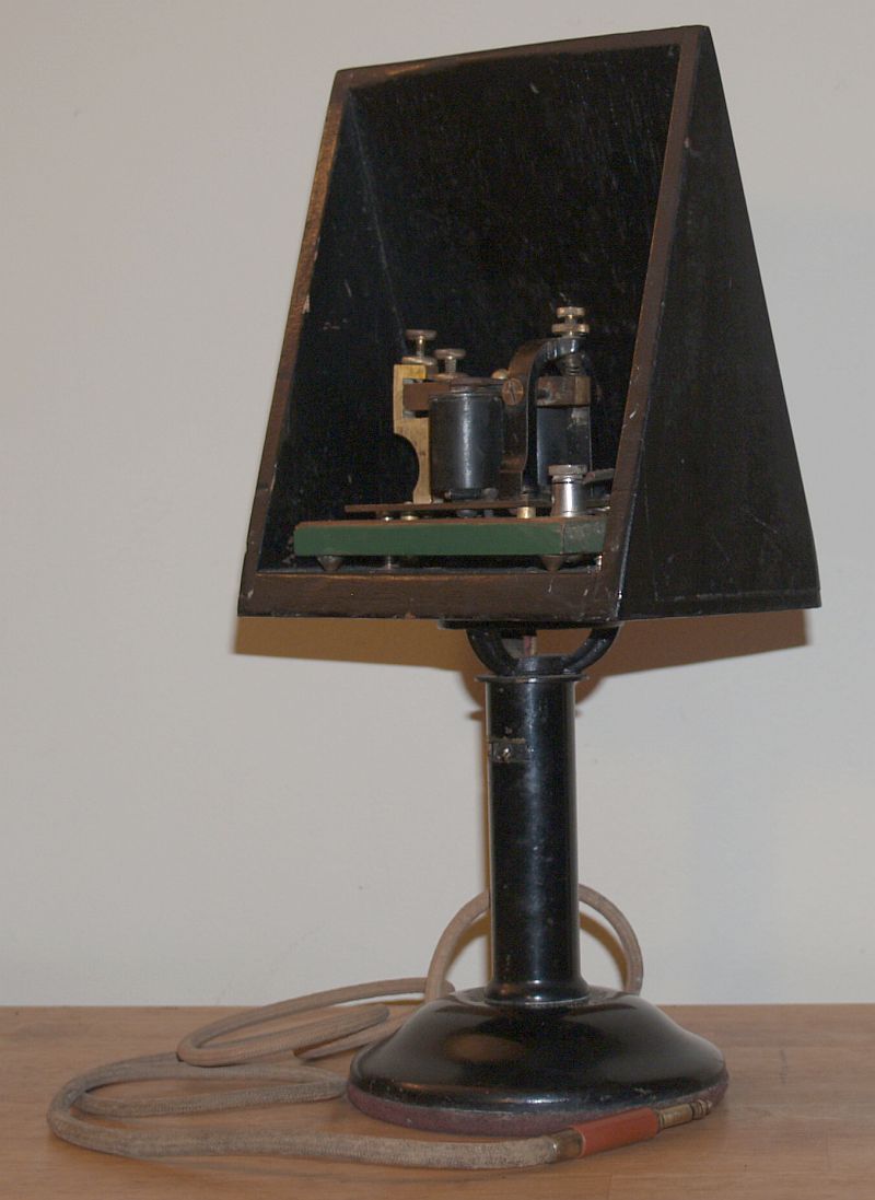
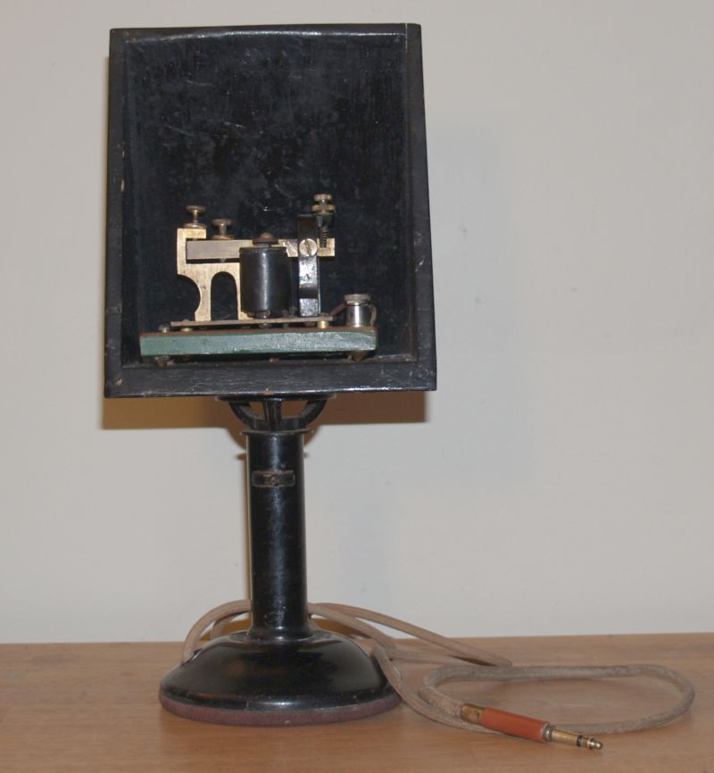
The sounder box is mounted on a stand that can rotate horizontally. The stand has felt on the bottom and is not intended to be permanently mounted to a table. A cord with a 1/4-inch phone plug routes through the base up to the box for connection to the sounder. The base of the sounder box is shown below.
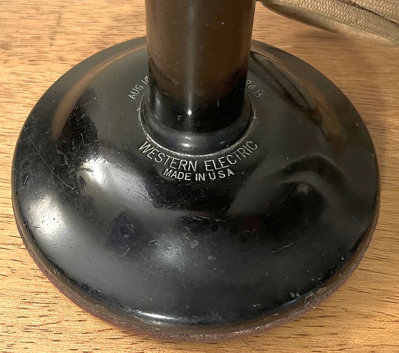
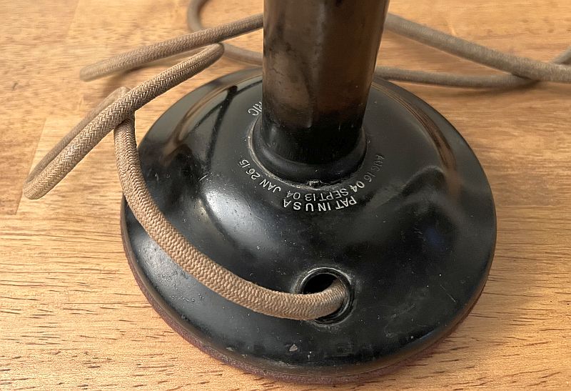
The patent information stamped into the base indicates the sounder box was made in the early 1900s.
Below is a picture of the sounder that is mounted in the box.
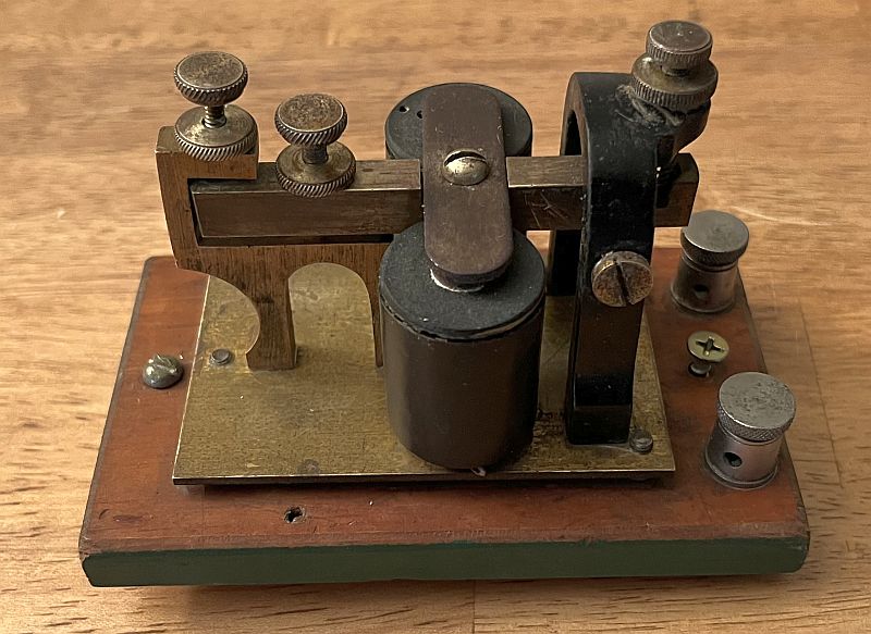
The sounder has no markings on it. As such, I am unsure that it was manufactured by Western Electric. Its resistance is 18.4 ohms. The sounder will activate at 3.8 Volts and draws 0.22 Amps to hold it closed. The sounder does work.