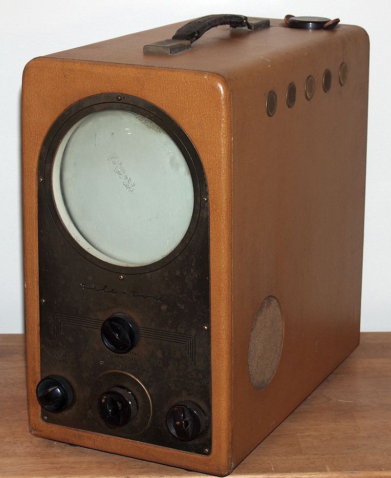
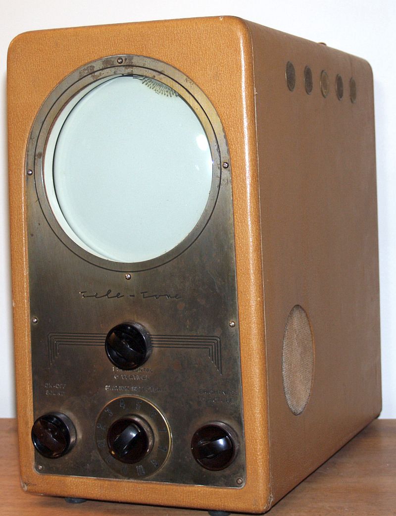
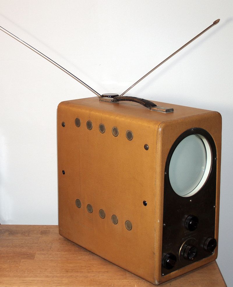
Teletone Model TV 208 Television Receiver
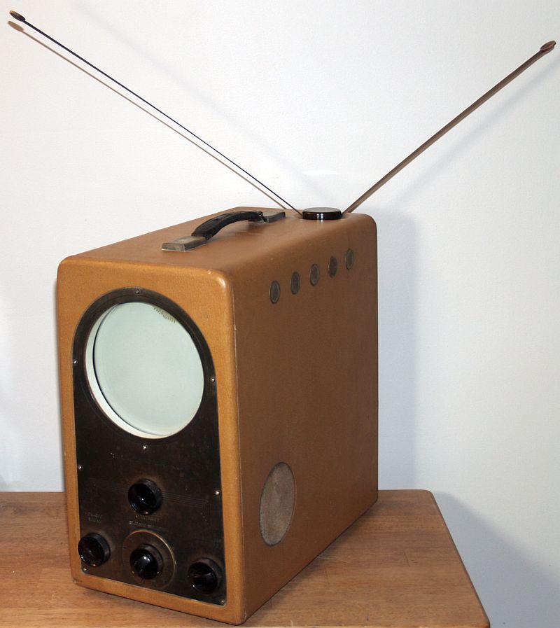
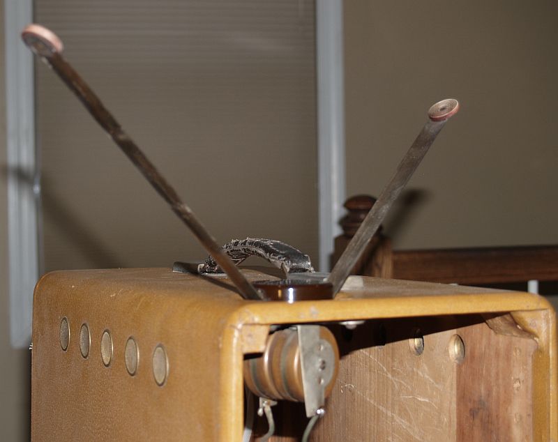
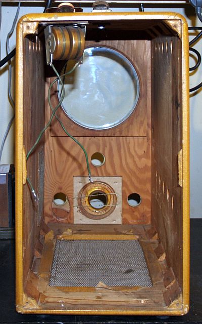
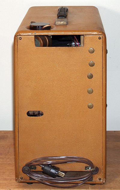
The television has a built-in antenna on the top rear of the cabinet. The antenna comprises two individual elements that can be pulled out, similar to a steel tape measure.The picture below shows the antenna partially extended along with the antenna steel tape cylinders inside the cabinet.
The television is light-weight because it has no power transformer. All of the vacuum tube filaments are in two series parallel combinations. The television has a ballast resistor assembly (comprising three power resistors) that plugs into a tube socket to reduce the line voltage to that required for the dc power supply. The television has a selenium rectifier to produce the B+ voltage and a 25Z6GT full wave rectifier tube to produce the negative low voltage. The unit requires an isolation transformer for servicing.
The controls on the front panel include:
On/Off Switch and Volume Control
VHF Channel Selector Switch/Fine Tuning Control
Brightness/Contrast Control
Horizontal Hold/Vertical Hold Control
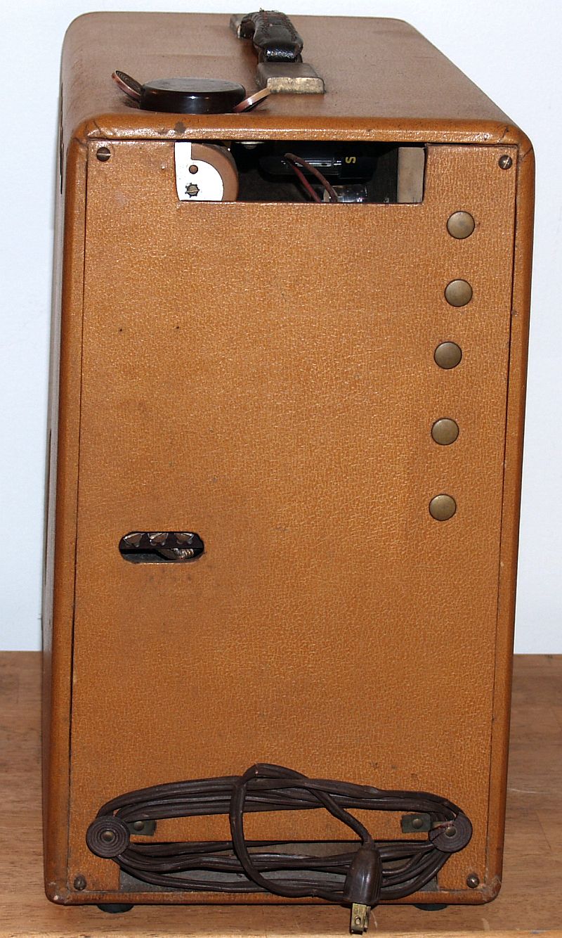
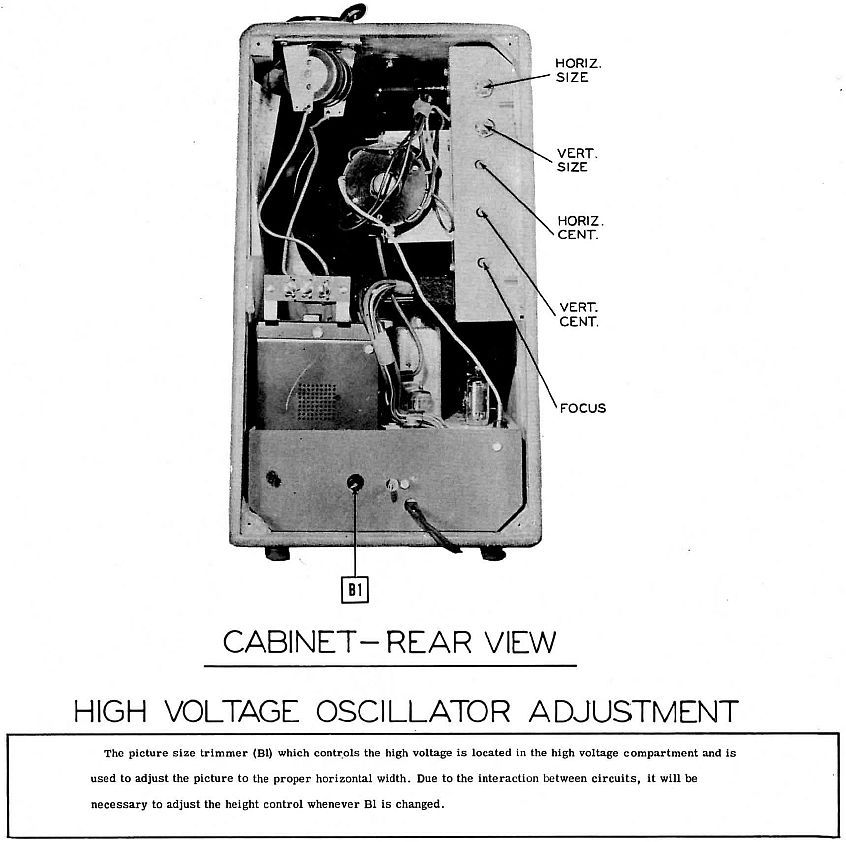
The controls on the rear include:
Horizontal Size
Vertical Size
Horizontal Centering
Vertical Centering
Focus
These controls are accessed by removing the rear cover, or removing the metal plugs on the rear cover.
The television has two individual chassis as shown in the picture below. The picture shows the rear of the television with the rear cover removed.
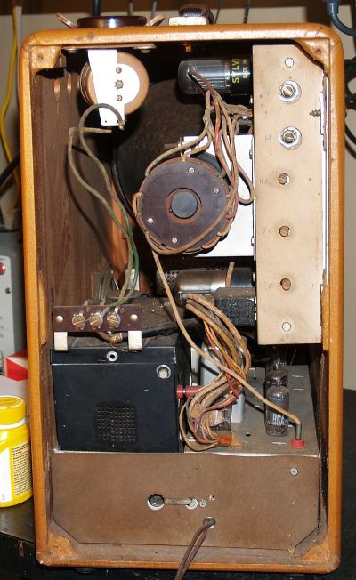
The chassis mounted to the bottom of the cabinet contains the RF and IF circuitry as well as the high voltage oscillator. The chassis mounted to the side of the cabinet contains the video sweep circuitry and the CRT. Interconnections between the two chassis is made through a Cinch Jones multi-pin connector that carries voltages, a small bananna plug that carries the video, and a large bananna plug that carries the high anode voltage. Both chassis are held to the cabinet with phillips oval head finishing screws with countersink washers, most of which were missing when I received the television. In fact, the lower chassis was not fastened down. The upper chassis was held in place with only two of the four screws.
I could not find a direct replacement for the original phillips oval head finishing screws with countersink washers. However, I found a package of 50 each #8 x 1-inch black phillips oval head finishing screws with countersink washers that are used to fasten interior automobile parts. I sawed of the end of the screws such that about 0.725 inches of the screw threads extends past the washer. This length will ensure the screw will not touch any components underneath the RF-IF chassis. The screw holes on the Sweep chassis are external to the chassis such that the length of the screws is not a concern.
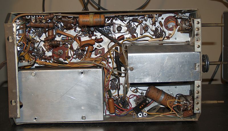
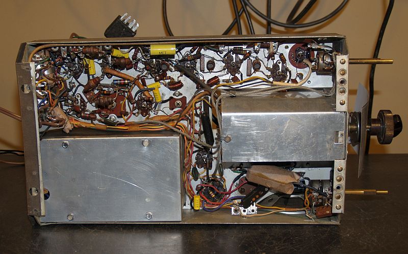
The pictures below shows the lower RF-IF chassis when removed from the cabinet.
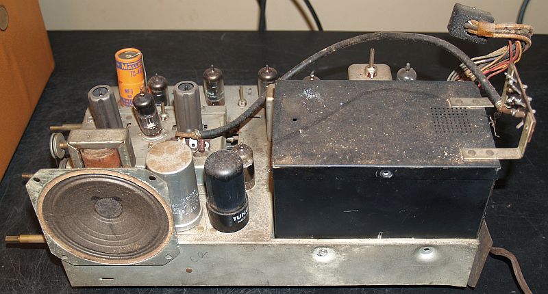
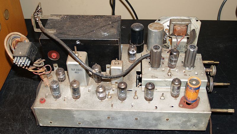
Note the exposed orange capacitor at the lower right of the last picture above. It is the result of a previous repair. All the screws that hold down the top of the black high voltage cage are missing. Below is a picture of the bottom of the chassis.
Note the two missing screws in the cover for the bottom of the high voltage cage.
I found that #6 x 3/8 inch hex washer head self drilling screws work well to secure the bottom and top covers of the high voltage cage. I used 410 stainless steel screws.
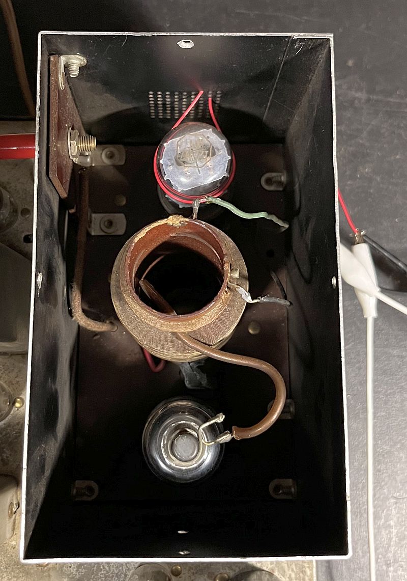
Below is a picture of the inside of the bottom of the high voltage cage.
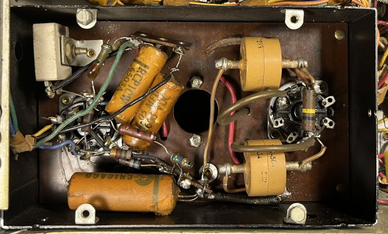
The high voltage rectifier socket has two yellow-colored button-type 6000V filter capacitors. I did not replace those during restoration because I believe they are not a high failure item.
Below is a picture of the safety switch.
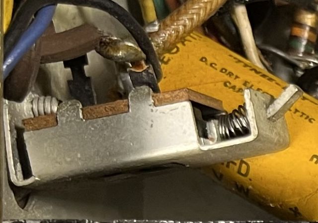
The safety switch is supposedly deactivated when the television rear cover is removed and activated (closed) when the cover is in place. However, this switch is permanently activated becasue the plunger is deliberately bent to hold the switch closed. Note the rectangular plunger end is bent upward and the spring is compressed. I believe this was done sometime in the past because the rear cover is probably slightly warped such that it will not hold in the switch plunger. The rear cover is flimsy and over time will not have sufficient rigidity to hold in the switch plunger. The switch could have been bypassed by shorting out the switch and not bending the plunger, but I suppose bending the plunger was quicker.
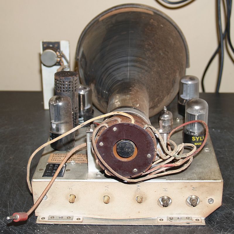
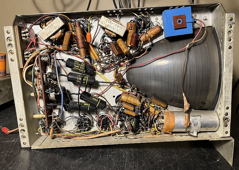
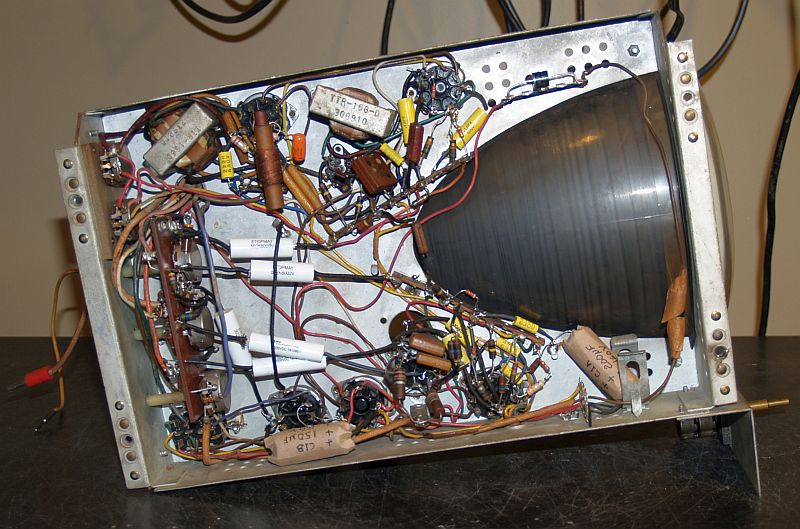
The pictures below shows the upper sweep chassis when removed from the cabinet.
Restoration of this televison was complicated by the fact that the SAMS Photofact electrical schematic did not agree with the original wiring present in the television. SAMS provides service data with the cooperation of the manufacturer. Apparently, the manufacturer did not provide accurate or current information. Schematic errors are discussed below.
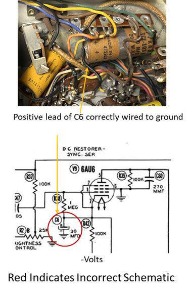
One schematic error concerns the polarity of C6. The positive lead of C6 is correctly wired to ground but the schematic has the polarity reversed. This situation is shown below.
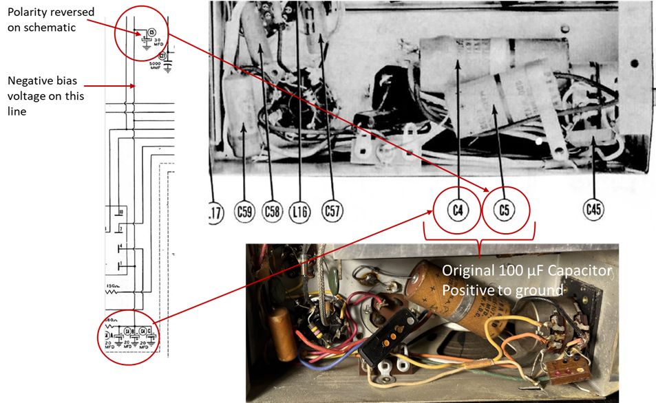
Another schematic issue concerns an undocumented schematic change and schematic error. Four capacitors shown in parallel in the schematic are replaced by a single 100 uF capacitor. In addition, the polarity of one of the parallel capacitors is reversed on schematic. This situation is shown below.
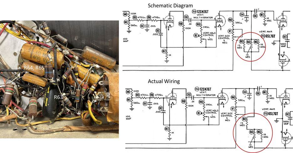
Another schematic issue concerns a series and parallel resistor combination. The actual circuit has one resistor in series with two parallel resistors instead of all three resistors in parallel as shown below.
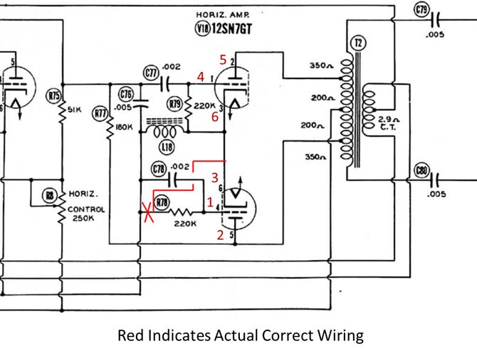
Another schematic issue concerns the horizontal amplifier where the wiring to the two triodes is reversed and R78 should be connected to pins 3 and 6 as shown below.
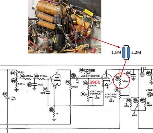
Another schematic issue concerns the vertical multivibrator. R59 should be 390k; the parts list correctly lists it as 390k. R60 comprises 2 resistors in parallel; the combined resistance is 926k ohms. The parts list shows R60 as 390k. This situation is shown below.
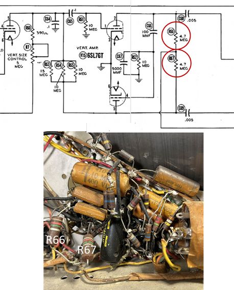
Another schematic issue concerns the vertical amplifier. R66 and R67 are installed as 8.2M-ohm resistors. Both resistors measured 10M-ohms; I did not replace them during restoration. The schematic and parts lists identifies them as 4.7M-ohms. This situation is shown below.
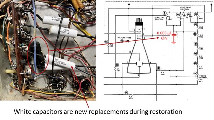
Another schematic issue concerns an added capacitor that is not documented in the schematic. A 0.005 �F/6kV capacitor is not on the schematic or in the parts list. the capacitor is connected from the Horizontal Centering and Vertical Centering controls to ground. this discrepancy is likely a design change added to isolate the horizontal control from the vertical control. This situation is shown below.
Another schematic issue concerns a transformer winding resistance error. The resistance of two of the three windings of the high voltage transformer measured close to the stated value. The resistance of one winding (circled in red in the picture below) measured significantly lower than the stated value.
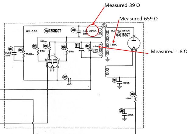
This large discrepancy usually would indicate a shorted winding. However, the the high voltage oscillator works and operates at approximately 157 kHz. The television has a reasonably bright picture. However, variable capacitor (B1) does not seem to have any affect on the oscillator frequency and subsequent high voltage output and horizontal width (as stated in the SAMS Photofact) The stated winding resistance value probably should have been listed as 25 ohms instead of 250 ohms.
Another schematic issue concerns R83 in the feedback loop of the high voltage oscillator. SAMS Photofact states the value of R83 is 7500 ohms. I measured the value as 27k ohms, much higher than it should be. A 27k-ohm measurement on a 7500-ohm resistor seems quite unusual. Old resistors often read higher than the original value, but usually not that much higher. I could not read the actual resistor value because the color bands were faded. The Riders schematic states R83 is 18k. This value seems more realistic considering the measured value is 27k. However, the value of C85 in the SAMS schematic (1500 pF) differs from the value of the equivalent capacitor in the Riders schematic (360pF). As such, the time constant of the RC network differs by approximately 1.7:1. This situation is shown below.
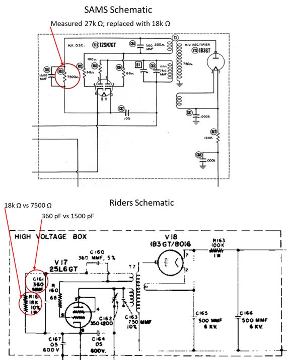
I could not resolve this discrepancy but I decided to replace the original resistor with an 18k-ohm resistor. The high voltage oscillator does work with this modification.
Assuming the television worked when it left the factory, I generally favored the actual wiring over the schematic for the issues noted above. As such, I did not change any existing wiring to match the schematic. However, I did find several wiring inconsistencies that I regarded as errors as discussed below.
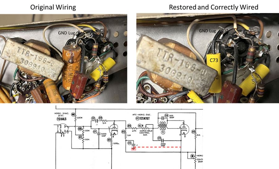
One wiring error concerned C73 in the AFC/horizontal oscillator circuit. Capacitor C73 is wired to pin 6 of V17 instead of to the adjacent ground lug as shown below.
Another wiring error concerned C50 in the sound circuit. Capacitor C50 should have been connected to pin 6 of V10 instead of pin 7 as shown below.
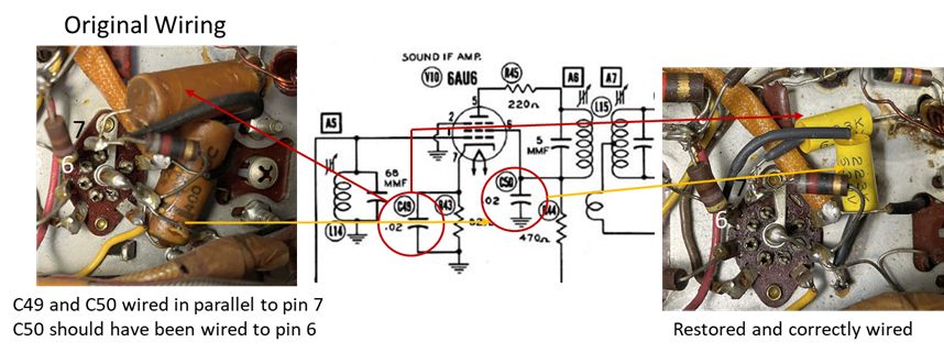
Neither of the above wiring errors whould make the television inoperable. The performance may be a bit compromised, though.
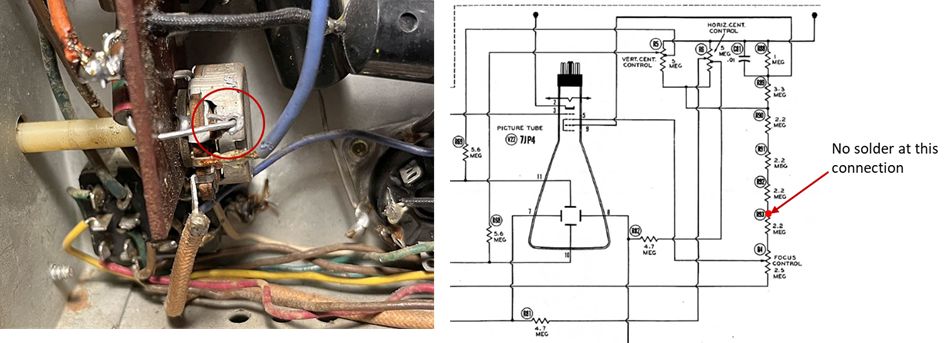
I did find a connection that was originally not soldered as shown in the picture below. The non-soldered joint is circled in red. Note there is no solder on the 2.2 M-ohm resistor connection to the Focus Control. The wire was crimped sufficiently such that this non-solder joint did not cause a malfunction.
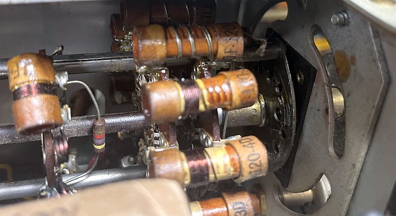
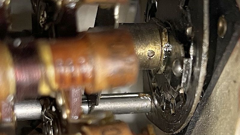
Another problem I found with this television concerns the channel selector rotary switch. The channel selector rotary switch is a wafer-type switch with a ball bearing that provides a detent at each channel position. The ball bearing was missing when I received the television and the switch rotated continuously with no detent to ensure the switch was properly positoned at any of the thirteen channel positions. The place where the missing ball bearing should be is shown below.
I purchased a kit of ball bearings containing diameter sizes from 1mm to 8mm with which I could experiment and determine the proper size. A 4mm diameter ball bearing works perfectly. The replaced ball bearing is shown below.
To electrically restore the television, I replaced all of the capacitors, including the one exposed electrolytic capacitor replaced during a previous repair. To replace that exposed electrolytic capacitor, I first gutted an old insulated electrolytic capacitor I saved from a previous television restoration. The gutted capacitor is shown below. I saved the metal insulated case, the phenolic plug on the end, and the plug retention ring.
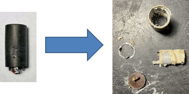
I inserted a new electrolytic capacitor inside and sealed it with the plug, retention ring, and epoxy. The picture below shows the RF-IF chassis with the "new" electrolytic capacitor. The "new" capacitor is the black cylinder with the white label on the lower right.
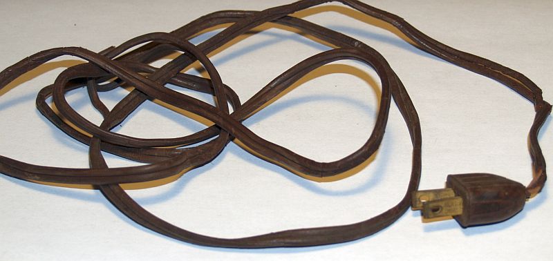
I replaced nine resistors that measured significantly higher than their original values. I replaced the power cord that had dry rotted. Below is a picture of the original power cord. You can see where the insulation had stiffened and broken away.
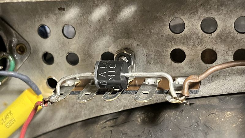
Although the selenium rectifier tested good, I replaced it with a single 6A10 (P600MG, equivalent) silicon diode as shown in the image below.
Below is a picture of inside the empty cabinet after cleaning.
Below are pictures of the undersides of the restored chasses.
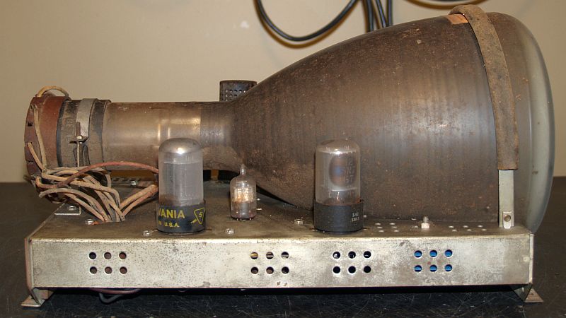
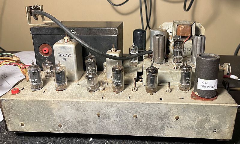
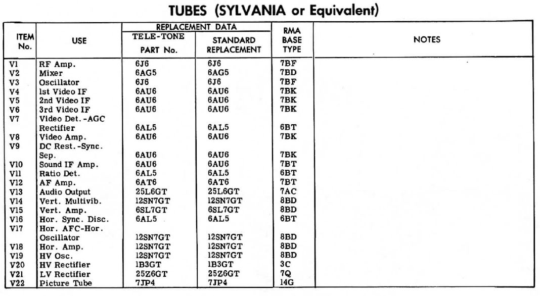
The television comprises 22 vacuum tubes. The picture below shows the tube layout.
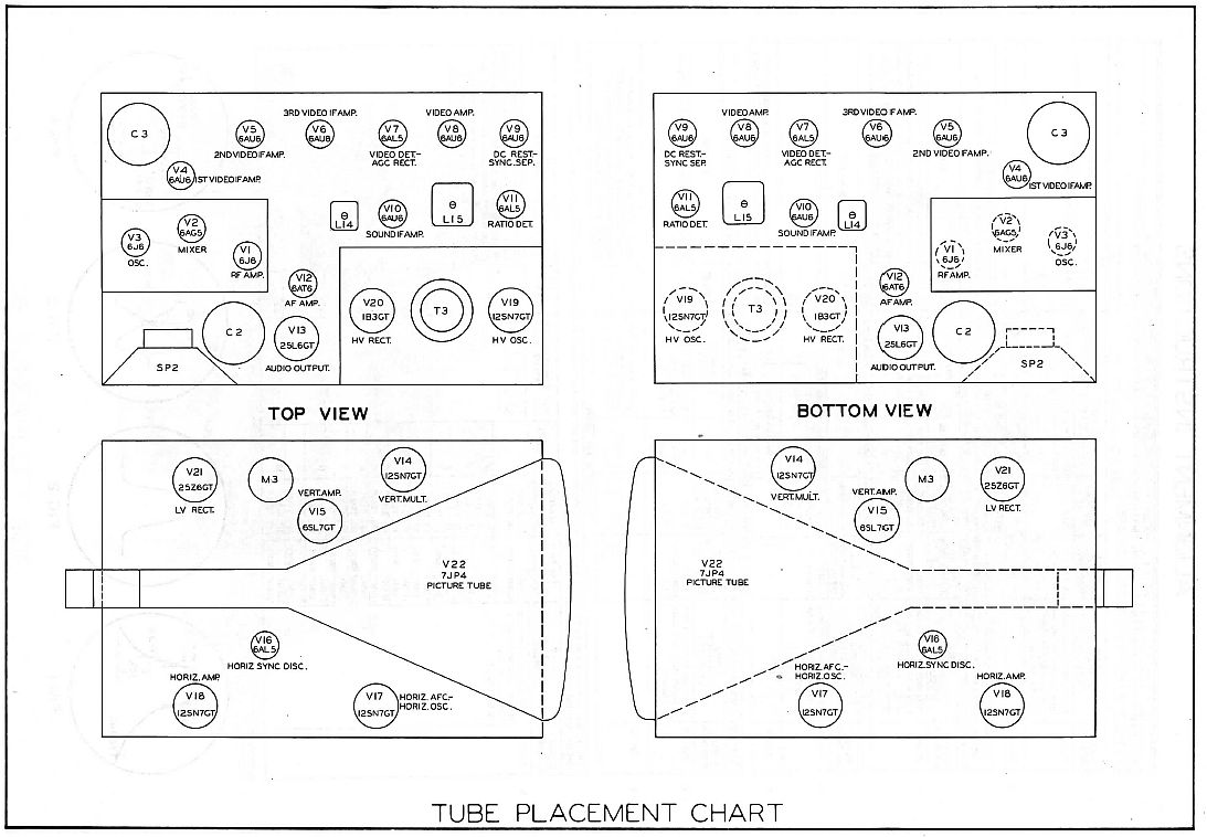
Tube Compliment
The picture below describes the controls on the rear of the television.
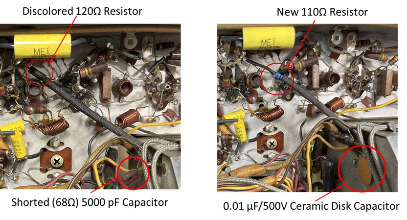
Initial power up using a variable transformer was not successful. The television drew excesive current and the isolation transformer hummed. Resistance measurements on the B+ voltage line to ground traced the problem to C23, a bypass capacitor for the B+ voltage to the tuner. The C23 bypass capacitor significantly lowered the B+ voltage. Capacitor C23 is somewhat discolored and appears to have a burnt spot. The resistance measured 68 ohms. The capacitive value of C23 is not critical. I replaced it with a 0.01 �F/500V ceramic disk capacitor. Ceramic disk capacitors provide good bypass for RF signals. Excessive current also overheated R18, a 120 ohm resistor. I replaced R18 with a 110 ohm resistor because I did not have a 120 ohm resistor on hand. That difference should not affect performance. The picture below shows the defective components and the repair.
All of the vacuum tubes but one tested good. The 1B3GT high voltage rectifier tube tested bad with no emission. These tubes are generally reliable and do not go bad. As such, I did not initially test this tube and I could not figure out why no high voltage was being produced. When I finally tested this tube on three different tube testers, absolutely no emission was displayed by each tester. However, I could see a glow from the filament, which is not normal, I think. Replacing this tube restored the high voltage.
In analyzing the high voltage problem I wrapped a wire around the 12SN7GT high voltage oscillator tube to view the oscillations on an oscilloscope and measure the oscillator frequency. The oscillator sample loop (red wire wrapped around the vacuum tube) is shown below.
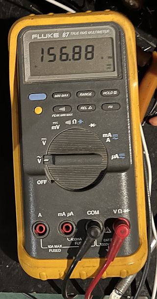
The oscilloscope trace and oscillator frequency measurement is shown below.
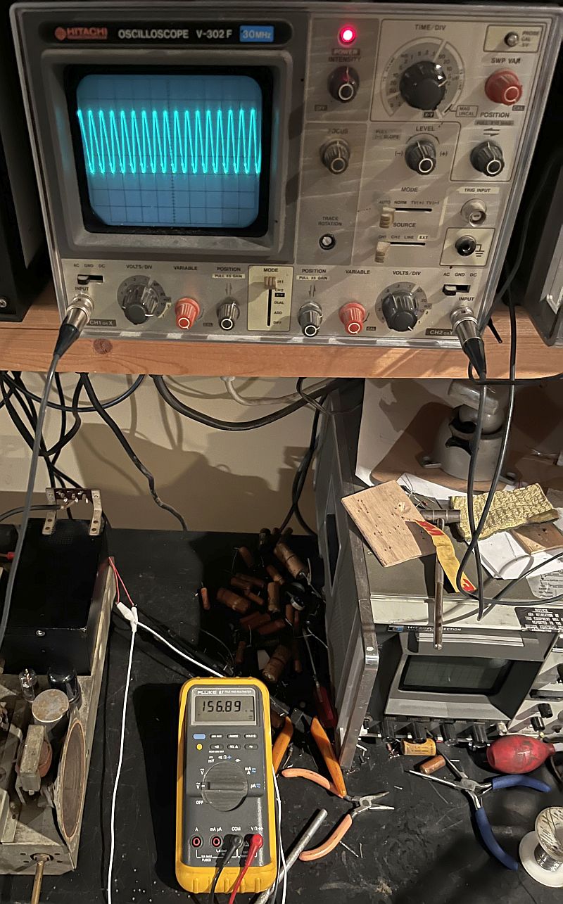
Note the oscillator frequency is near 157 kHz that is higher than most high voltage oscillators I have seen. Most high voltage oscillators I have seen operate at 15.75 kHz. This oscillator operates at a much higher frequency so that its frequency can be tuned across a tuned circuit to vary the voltage to adjust the horizonttal size (and brightness), but I could not get this adjustment to make an effect.
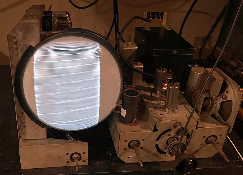
After fixing the high voltage, I again used a variable transformer to slowly bring up the line voltage while monitoring the B+ voltage. Because the television has a negative power supply, the B+ positive voltage is lower than 150V (the plate-to-cathode voltage will be much higher). The first raster is shown below.
The horizontal width is too narrow, but adjusting the horizontal width control prduced a raster completely across the screen as shown below.
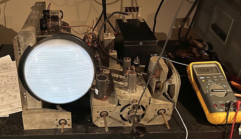
The digital meter in the picture above shows the high voltage oscillator frequency in kHz.
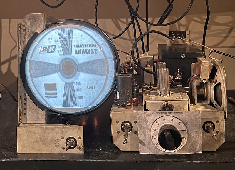
Below is a picture of a test pattern produced by my B&K Television Analyst as displayed by the television.
Further testing revealed that the 6AL5 video detector/AGC rectifier vacuum tube was intermittant in its socket. Wiggling it sometimes corrected the problem. I discovered a poor solder joint to a coil in the circuit, but after resoldering, the intermittant problem still persisted. I eventually replaced the 6AL5 vacuum tube.
Another intermittant problem concerns the 6AT6 audio output tube. It is also intermittant in its socket. Wiggling it usually corrects the problem. Although SAMS Photofact states the tube is a 6AT6, sometime in the past, a 6AV6 was installed. A 6AV6 has more gain than a 6AT6, but that fact should not be a problem. Cleaning the tube socket seems to have fixed the intermittant problem.
Below is a picture of receiving a television program.
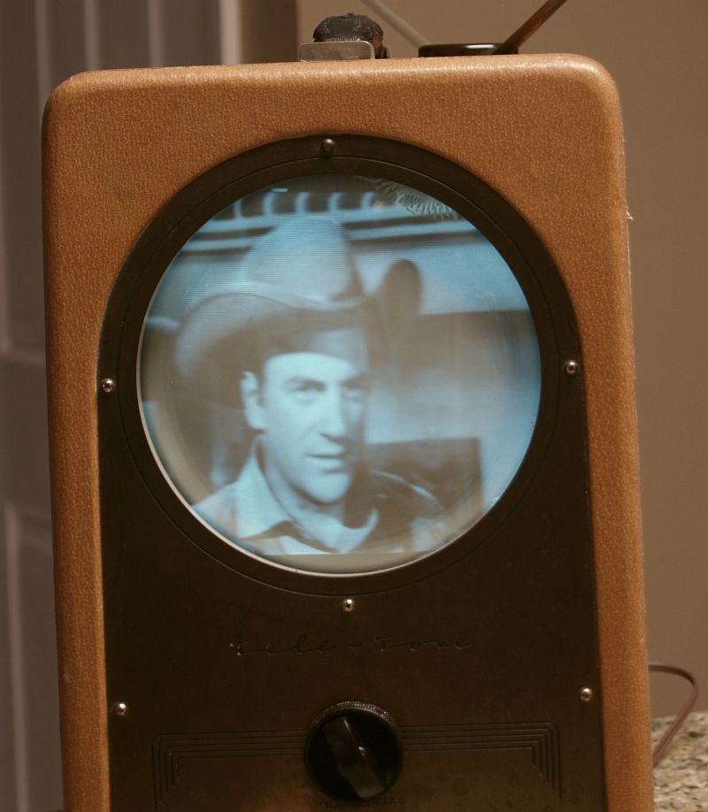
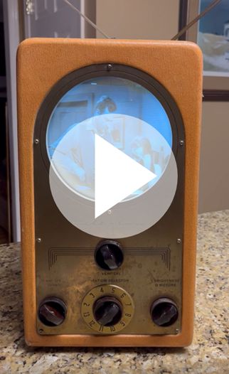
Click on the image below to see a video of the television receiving a program (Gunsmoke).
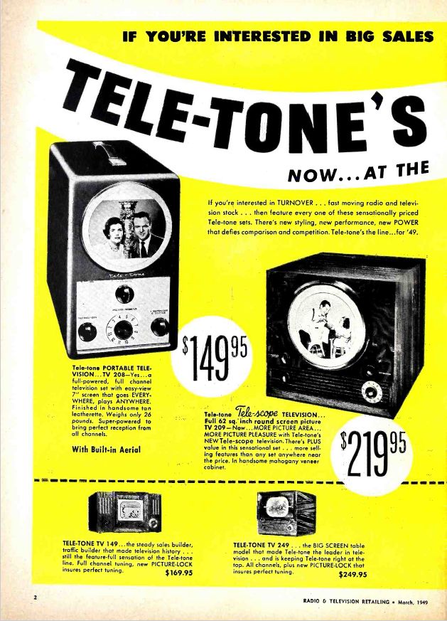
Below is an advertisement in the March 1949 issue of Radio & Televison Retailing magazine for this television. Note the price in 1949 was $149.95.
Below are other pictures of the restored television.
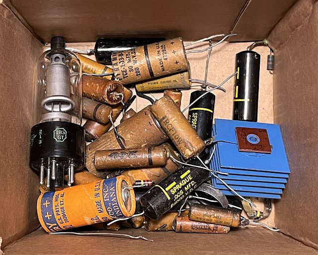
Below is a picture of the original parts that I replaced.
Below are pictures of the television when I received it.