WWV Radio-Controlled Clock

This is a digital clock I designed and built, initially over 20 years ago. In 2001, I upgraded the original
design to use a PIC chip for decoding and time keeping and I redesigned the the receiver for better performance.
This clock automatically synchronizes itself to the
National Institute of Standards and Technology (NIST) atomic clock and displays
the precise time of day. The NIST broadcasts time of day and other information
on 5, 10, 15, and 20 MHz. These shortwave stations also broadcast a time code
on a 100 Hz subcarrier using a modified IRIG-B format. My clock has a crystal-controlled
radio that receives WWV on 5, 10, and 15 MHz. The radio will scan for the strongest
signal. The clock has a Microchip PIC that decodes the 100 Hz time code to set
its internal clock to the correct time. A DIP switch tells the PIC which time
zone to use since WWV sends time in Universal Coordinated Time (UTC). The
clock also adds 1 hour for Daylight Saving Time (DST) and illuminates a LED when
DST is active. Pushing a button on the lower right of the clock will display the day
of the year as sent out by WWV. A switch to the right of the display sets the display
to display either local time or UTC. The meter in the center of the front panel
displays received signal strength. Three LEDs below the display indicate status
of the time setting. There is one LED each for seconds, minutes and hours. When the
clock has updated seconds, minutes, or hours, the appropriate LED extinguishes.
WWV sends out the time via the modified IRIG-B format in series. Seconds is synchronized
with the 1000 Hz tone at the beginning of the minute. When that tone is received, the
clock will set the seconds to zero. Next the minutes is transmitted, followed by hours,
followed by day of the year, and finally DST. Thus the LEDs extinguish in a sequence.
The internal radio does not remain on all of the time. Once the time has been set, the
radio turns off and turns on again 1.5 hours later. Thus the time is updated
approximately every 1.5 hours. If the signal strength is not sufficient, the clock
will not set but maintain the time it determines using its internal crystal-controlled
oscillator.
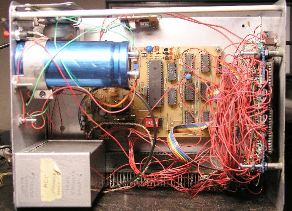
Below is a picture of the CPU board and the inside top of the clock. Yes,
I know it is messy, but it works. The mass of wires on the right is associated
with the display. The display was not redesigned.
Below is a picture of the receiver board located on the underside of the clock.
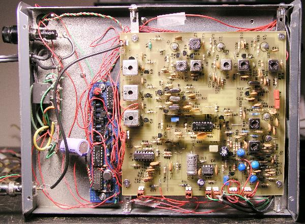
The original version of this clock comprised over 40 CMOS integrated circuits
and a single conversion radio receiver. Incorporation of the PIC allowed me to add
the day of the year feature and better error correction techniques. I designed
and added a dual conversion receiver to improve sensitivity and selectivity.
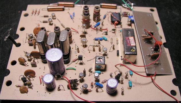
Below is a picture of the original digital electronics. This board was all
point-to-point wiring.

Below is a picture of the original receiver. I retained the original
point-to-point wired frequency select board (it uses blue perf board as seen
in the picture of underside of the clock shown earlier). However, some of the original circuitry was incorported
in the new digital board and therefore some ICs were removed.
Home