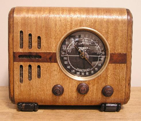
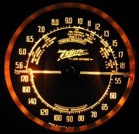
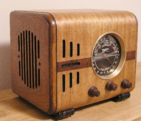
The pointer is brass and has the distinctive "Z" in the center. All knobs are wood and have the "lightning bolt Z" carved into them. The knob on the lower left is the on/off volume control. The center knob is tuning. The right-hand knob is the bandswitch and tone control. This switch has 4 positions. The most counterclockwise position is AM with treble cut. The next position clockwise is AM with no treble cut. The next position clockwise is shortwave with no treble cut. The last position is shortwave with treble cut.
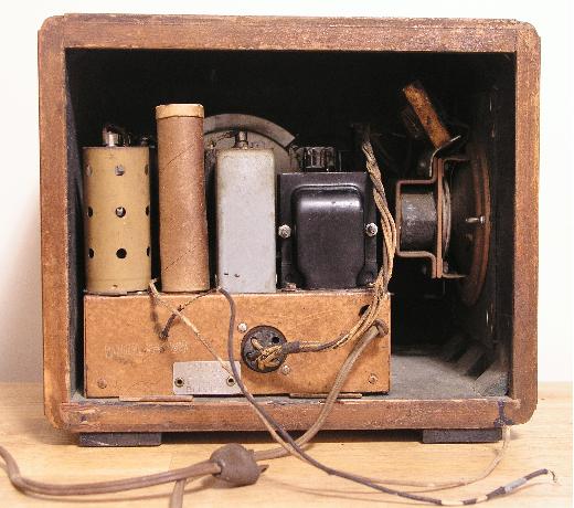
The radio chassis is copper coated although this example has some rust on the chassis.
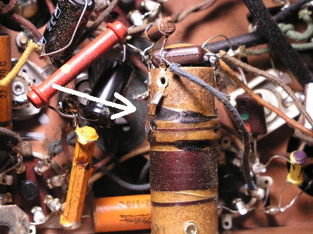
When I received this radio, the shortwave band did not work and the AM band calibration was about 30 kc too high. In addition, the speaker had several tears to the paper cone even though it had been repaired in the past. The dial string was also broken but the spring was still there. Upon inspection, I discovered that one wire of the feedback winding of the oscillator coil assembly was broken from its terminal. The other end of the winding was in place. Evidently, when someone replaced the filter capacitors, they accidently hit the wire and broke it. Fortunately, the broken wire end was barely accessible at the coil. I soldered a thin magnet wire from this end to the terminal and the shortwave band works well now. In addition, the AM band is more sensitive and the calibration came to within specifications. I also re glued the speaker paper cone and replaced missing parts of the cone. I replaced the dial string, also. The radio works well now. The picture below shows my repair to the oscillator coil.
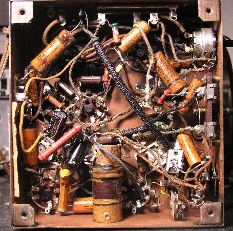
In repairing this radio, I noted that the Rider's schematic (and Bietman's as well) was in error. Resistors R2 and R3 are listed on the schematic as 10M and 22M - they should be 10k and 22k, respectively. The resistors installed in radio were correct, but the disagreement with the schematic made me wonder if someone replaced them to make the radio work with the defective oscillator coil. However, the resistors in the radio are original. Below is a picture of the bottom of the chassis.
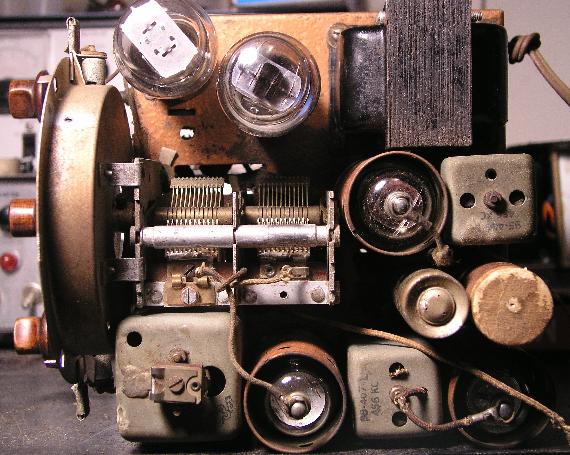
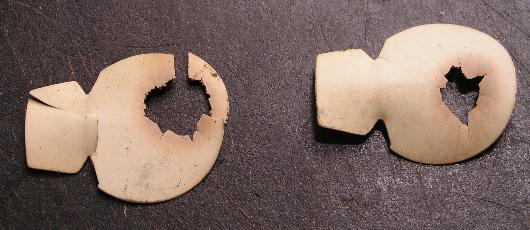
One component that deteriorates over time are the dial light reflectors located behind the dial. The are made of plastic and after a time, the dial light bulb burns a hole in them. Below is a picture of the reflectors removed from this radio. They are very brittle (note I broke one of them when I removed it) and there is a hole in both them. Note the scorch marks around the hole.
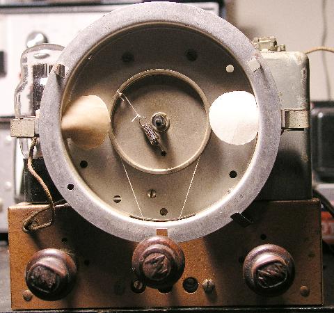
I made a replacement for these. I used a Teflon sheet for one and white cardboard for the other. (I did not have enough Teflon to make two). The picture below shows the replacement dial light reflectors installed and the new dial cord.
This problem with the dial reflectors is common. I had to make the same repair to the Zenith 6S229 Tombstone Radio I have.
Home