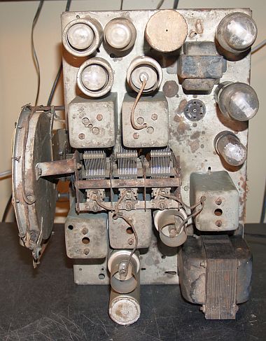
Below is a picture of the chassis after I removed it from the cabinet. Note that the chassis top is quite dusty.
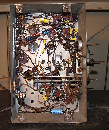
Below is picture of the botom of the chassis.
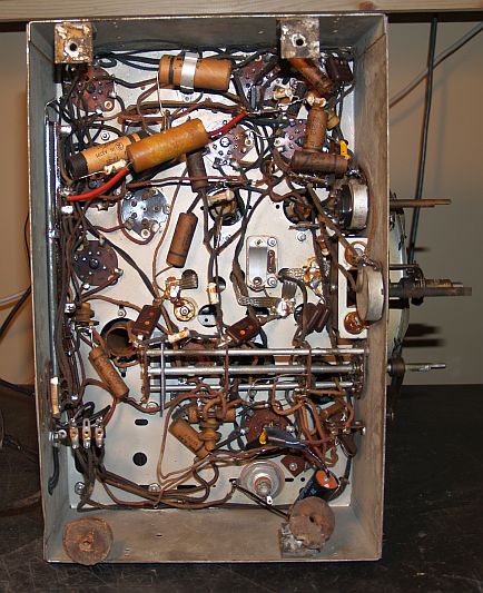
As can be seen in the lower right-hand side of the chassis, you can see that someone had added an power supply filter capacitor some time ago. The capacitor is not mechanically fastened and just hangs there. The original 16-uF filter capacitor was disconnected from the circuit, but the capacitor left in place. However, the other filter capacitors were left in the circuit. Before I could power up the radio, I had the replace the power cord as the original cord was severely frayed. I used the original plug when I replaced the cord. When I slowly powered up the radio using a variable transformer, the radio had significant hum, so I had to change all the filter capacitors, including the one replaced long ago.
The radio did not work when I powered it up. The problem was that the RF stage was not working because there was no B+ voltage on the plate of the RF amplifier tube. The dual-winding RF choke in the plate circuit had an open winding. I "replaced" the open winding by soldering a 100-uH choke I had in the junkbox in parallel with the open winding and the radio worked. Although the radio worked, sometimes the volume would suddenly increase substantially and then return to normal volume. This problem seemed to settle out after a while, but it is not normal. I decided to replace all of the capacitors and that approach seemed to fix the loudness problem.
Below is a picture of the bottom of the chassis after I replaced all of the capacitors. The replaced choke can be seen as the small red-colored coil in the lower center of the chassis just below the bandswitch.
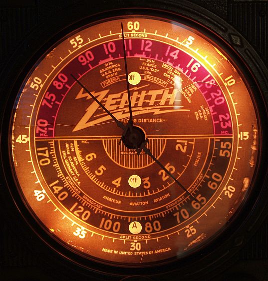
One of the dial lamps was burned out, too, so I replaced it. Below is a picture of the dial with the room lights off. Each of the three bands on the translucent dial have three different transparent colors to indicate the bands. The standard broadcast AM band is dark green and appears black (dark) in the photo. The 2.1 to 7 MHz shortwave band supposed to appear yellow. The 7 to 23 MHz shortwave band appears reddish. Each band has an associated circular hole near it where The word "OFF" appears whenever the band is not selected and when a band is selected, the letter "A", "B", or "C" appears to show a particular band is active.
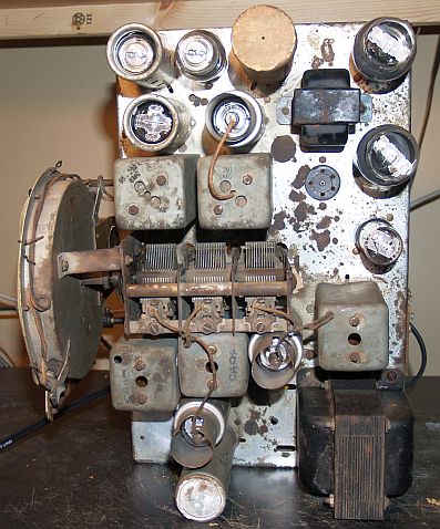
Below is a picture of the top of the chassis after I cleaned it with WD40.
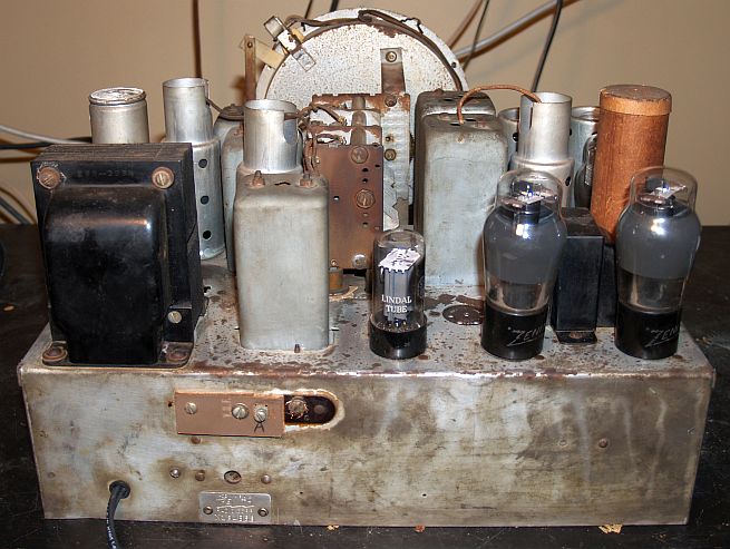
Below is a picture of the rear of the chassis after I cleaned it. Note that someone replaced one of the terminals on the original teminal strip with another terminal strip some time ago. The terminal strips are for connecting an antenna (marked "A") and ground.
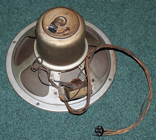
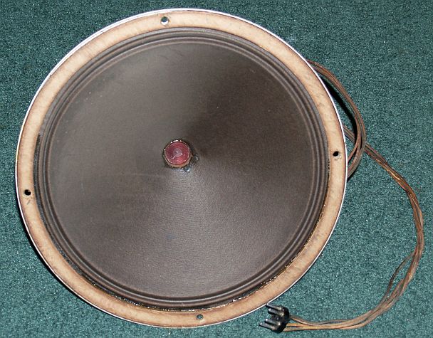
Below are pictures of the speaker removed from the cabinet. Both the field winding and the voice coil are good. The speaker cone is in excellent shape, too.
 |
 |
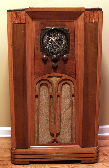
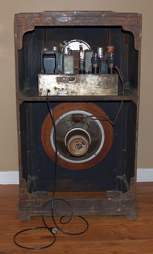
Below is a picture of the rear of the radio. Before mounting the chassis back in the cabinet I replaced the four original chassis mounts with new gum rubber washer mounts. The original mounts had "melted" and expanded such that they did not support the chassis at the proper height. I also removed an old mud (dirt) dauber nest from the inside top of the radio cabinet before installing the chassis back in.
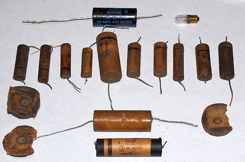
Below is a pictue of the parts I replaced. I had to scrape one rubber foot of the chassis and it is is such tiny pieces that I did not include it in the picture. The picuture does not include the chassis-mounted electrolytic capicitors that I left in place to maintain the original external appearance.
This radio did not have the model number anywhere on the chassis or the cabinet. It took a little research to figure out the model number. After determining the model number, I then located the schematic in the Riders Manual. The Riders electrical schematic cited in the table above is not exactly correct. For one thing, several of the capacitor numbers are repeated. However, the most significant problem with the schematic is the omission in the schematic of the wire potentiomenter on the rear of the chassis just above the serial number plate. This potentiometer is in series with the cathodes of the two 6F6 power tubes. The wiper of the potentiometer goes to "common" that is the end of the 570-ohm resistor of R9, the multi-section resistor (candohm in the parts list). This potentiometer is apparently used to balance the current through the two audio output tubes and minimize crossover distortion. The tube position chart in the schematic is not representative of the layout of this radio, either. The tube voltage chart in the schematic was not entirely correct as I measure 5.6V on the cathode of the 2nd audio 6C5 tube - consistent with my RCA Radiotron tube manual.
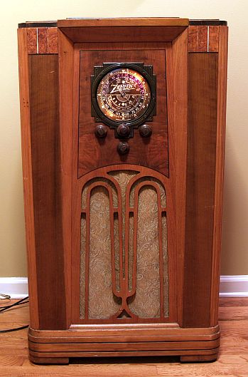
The radio works well with a long-wire outdoor antenna and has good tone and sensitivity. Below is a picture of the radio with it turned on.