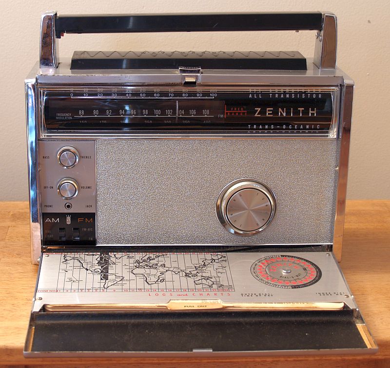
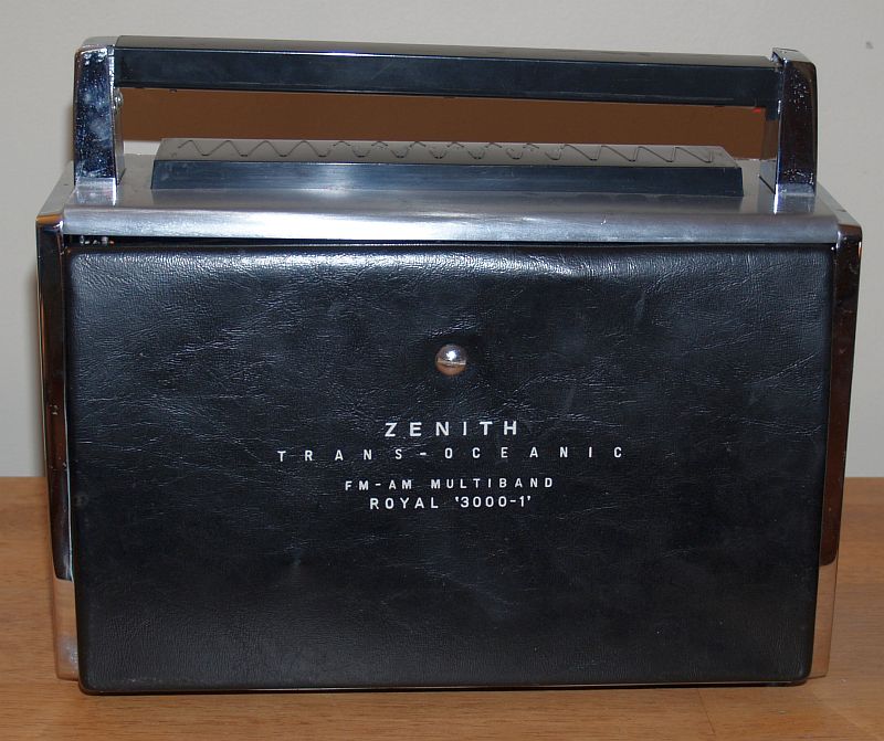
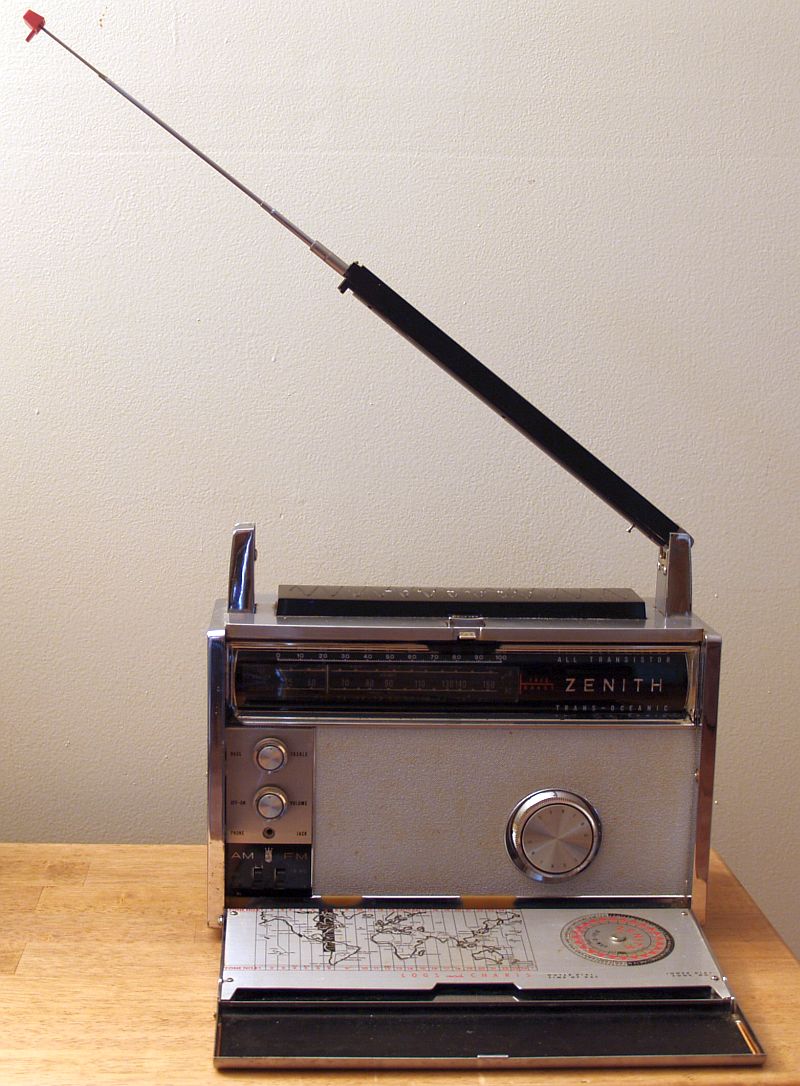
This is a 1960's Zenith Transoceanic Model Royal 300-1 AM-FM Multiband All Transistor Portalble Radio. The radio covers a wide range of frequencies: FM, longwave, Standard Broadcast AM, and 6 shortwave bands. It operates on 8 1.5 V "D" cell batteries which give up to 300 hours of performance under normal operating conditions. It has a 4x6 inch oval speaker and delivers undistorted power output of 500 mW. It can also operate on 12V dc external power through its external power jack.. The radio uses PNP type germanium transistors, so ground is positive volts.
The radio has a long whip antenna incorporated into the handle. One needs to be careful carrying the radio with the handle as the red tip of the whip can break with the weight of the radio - especially with a full compliment of batteries installed. The radio has the famous "wavemagnet" antenna under a plastic enclosure mounted to the top of the case.
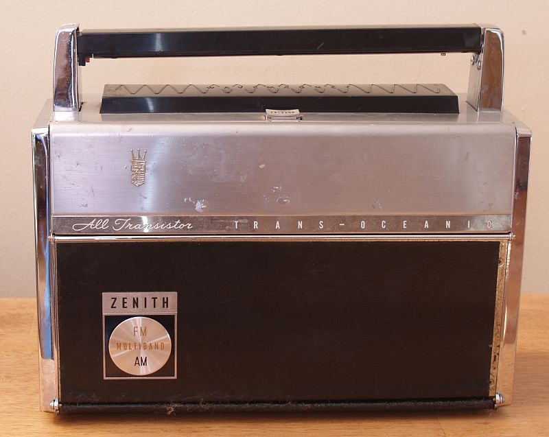
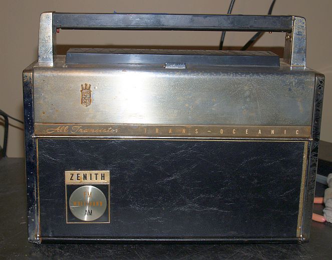
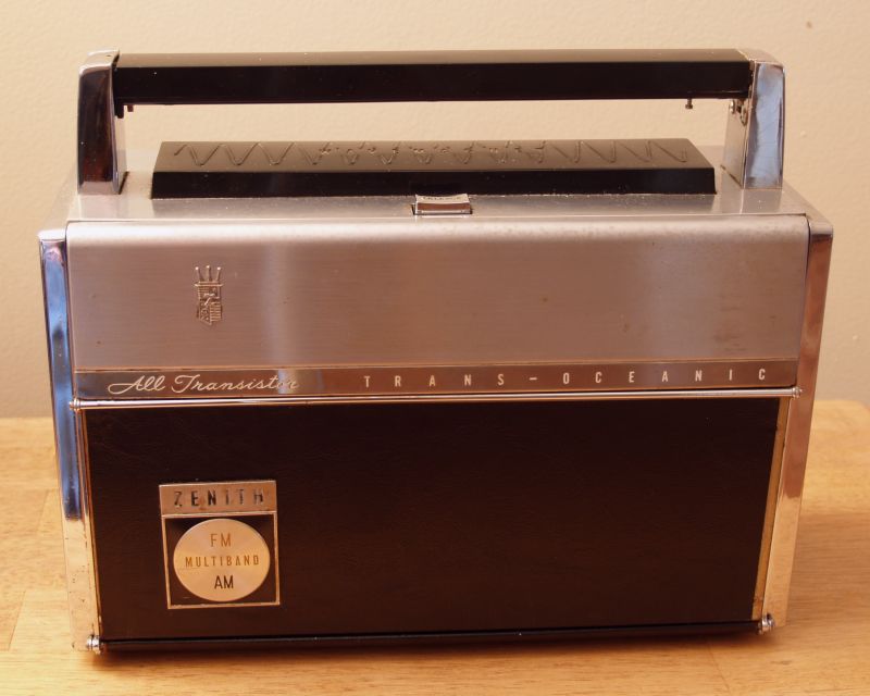
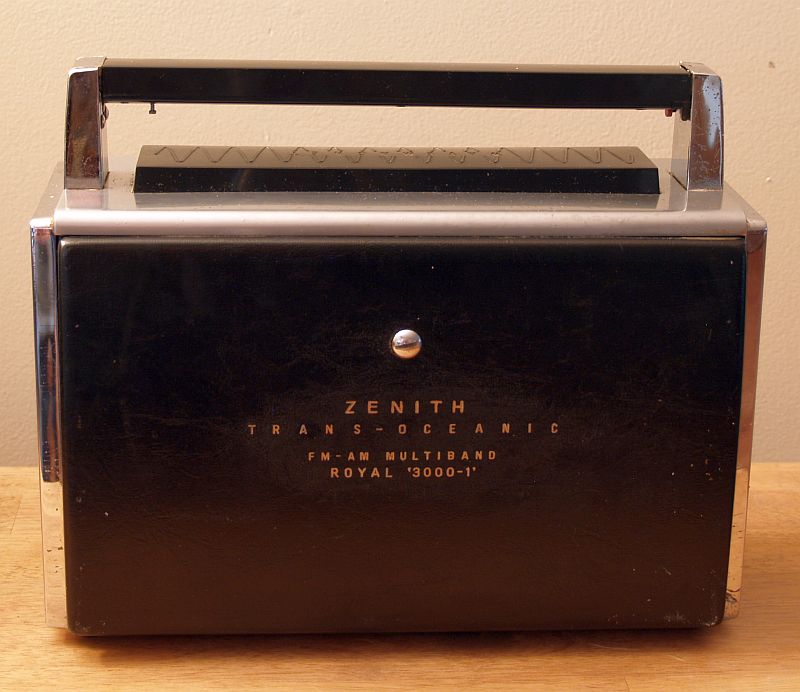
Below is a picture of the radio in its transport configuration.
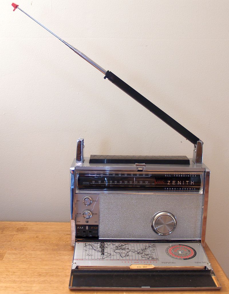
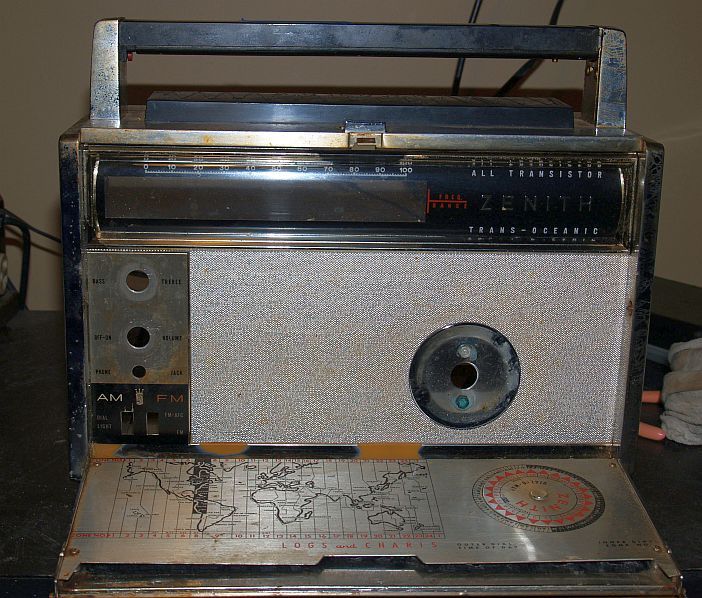
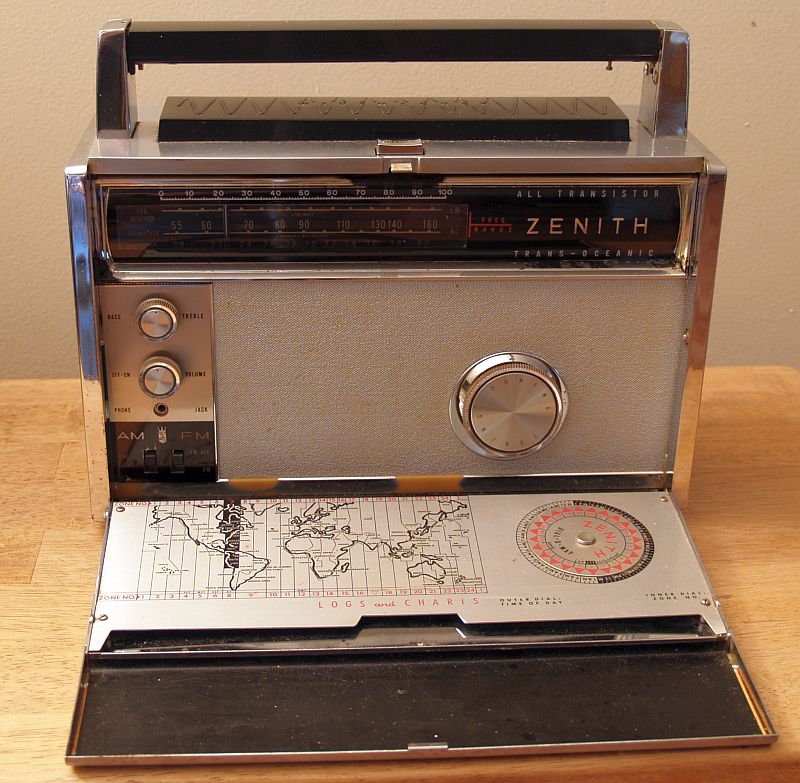
Below is a picture of the radio with its antenna partially extended.
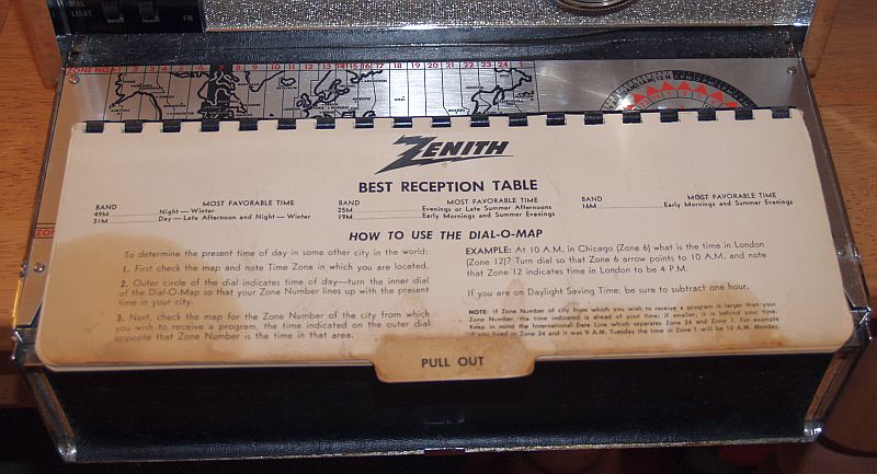
Below is a picture of the logbook that comes with the radio. Often, this logbook is missing.
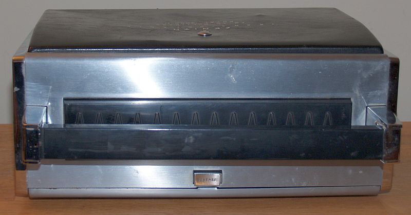
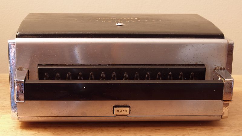
Below is a picture of the rear of the radio.
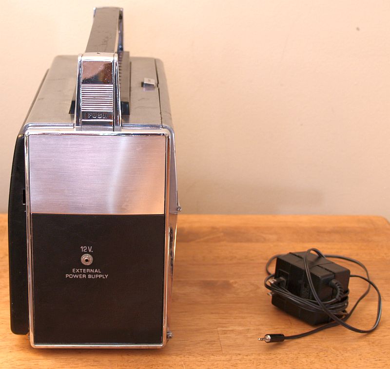
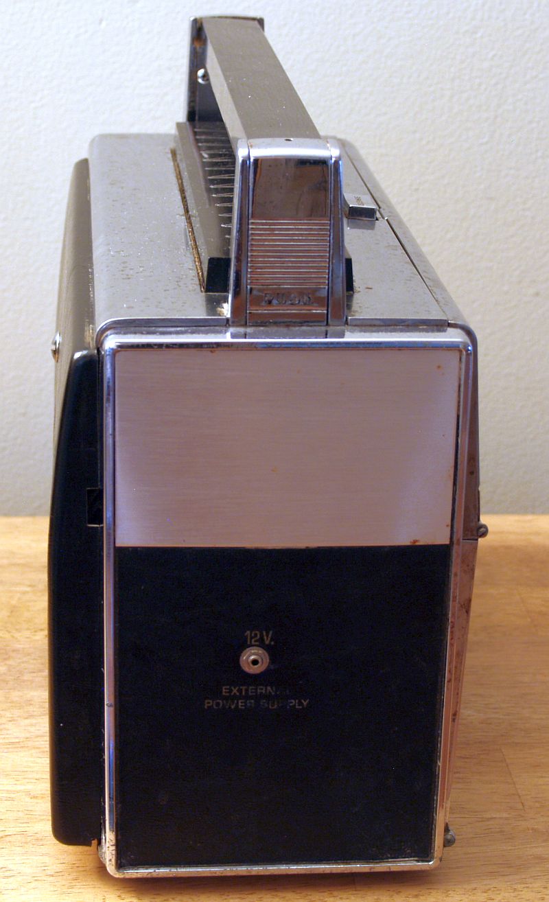
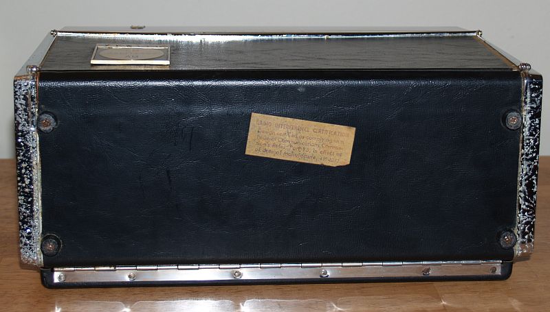
Below is a picture of one side of the radio. Also shown is a power supply I made from a Panasonic "wall wart" I made to power the radio. I installed a 12-V regular to regulate the higher voltage of the wall wart down to 12 Volts. And I made sure to have -12 Volts (ground as far as the wall wart is concerned) to the center pin of the phone plug. Positive 12 Volts is applied to the radio ground.
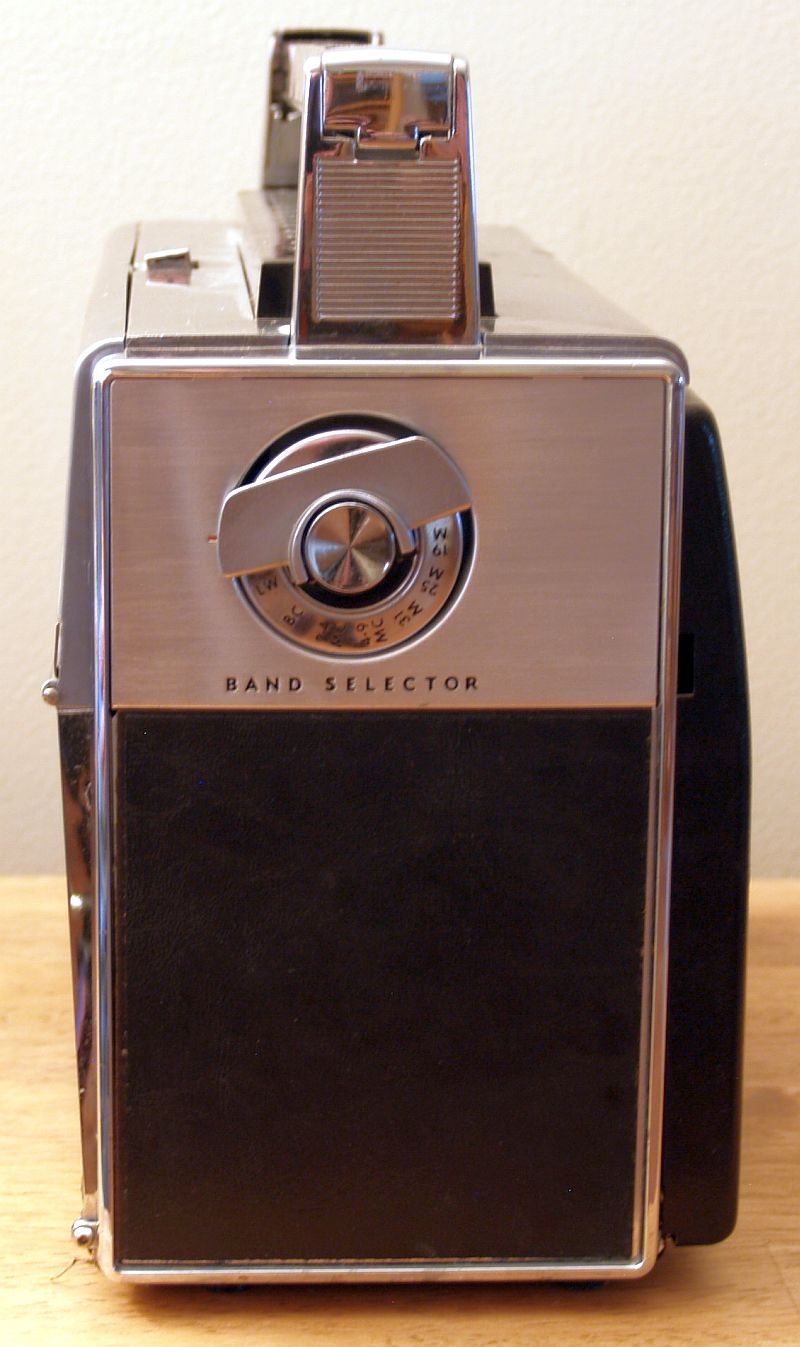
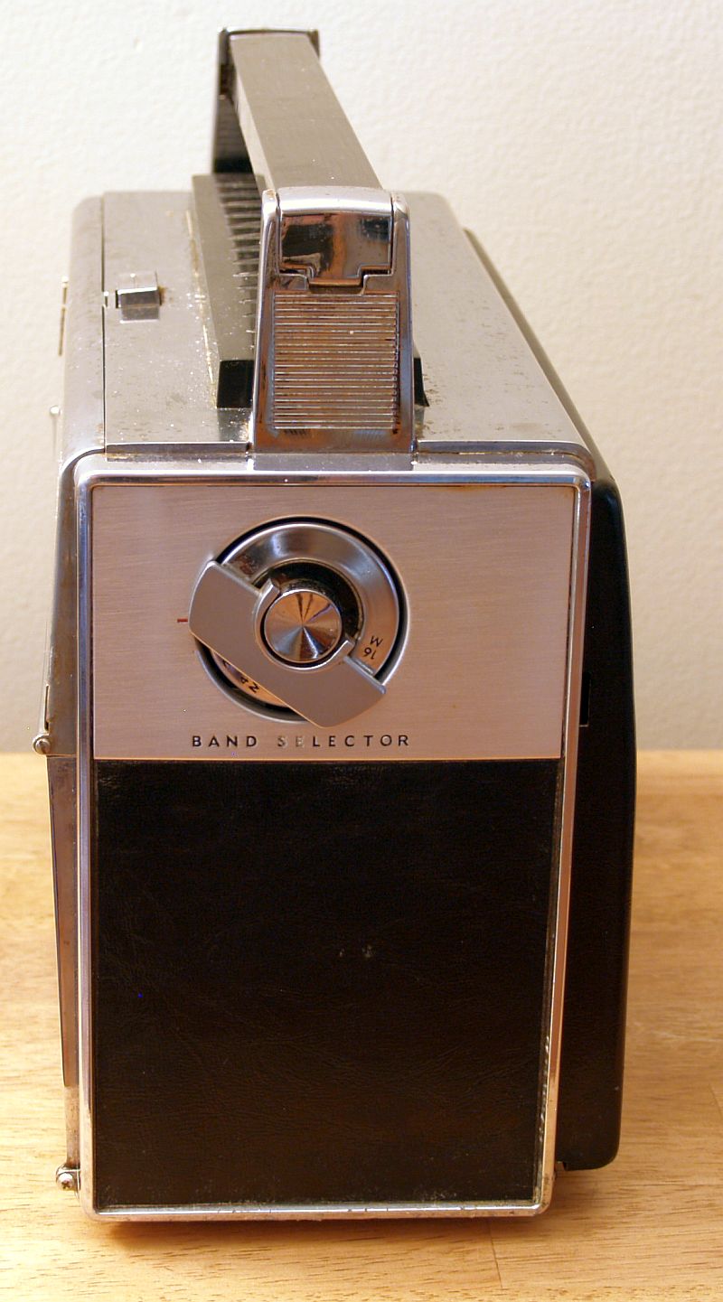
Below is a picture of the side opposite with the bandswitch. The markings on the bandswitch are not smudged as it appears in the picture. The dark spots are reflections from the room reflected off of the shiny silver bandswitch.
Below is a picture of the top of the radio.
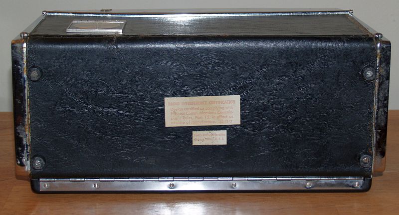
Below is a picture of the bottom of the radio.
Repair of a Severely Corroded Zenith Transoceanic Model Royal 3000-1
I acquired a second Zenith Transoceanic Model Royal 3000-1 that suffered from severe battery corrosion. The radio was not expensive because of its poor condition, but I wanted it becasue it had the log book that is often missing. Below is a picture of the front of the radio as I received it. The effects of corrosion are clearly evident even on the front of the radio.
Below is a picture of the top of the radio. The effects of corrosion are clearly evident.
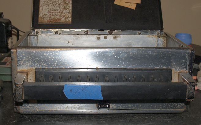
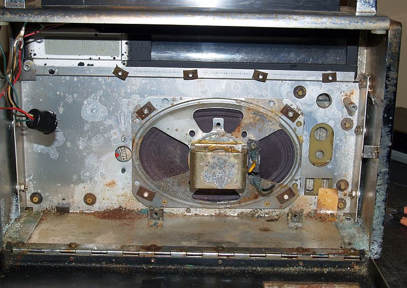
Below is a picture of the inside front of the radio as received. The effects of corrosion are clearly evident.
Below is a picture of the inside of the radio with the chassis removed as received. The effects of corrosion are clearly evident.
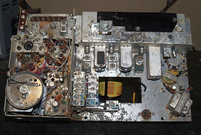
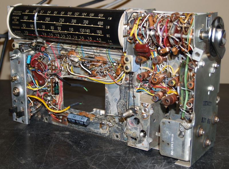
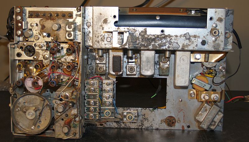
Below is a picture of the radio chassis as received. The severe corrosion is evident.
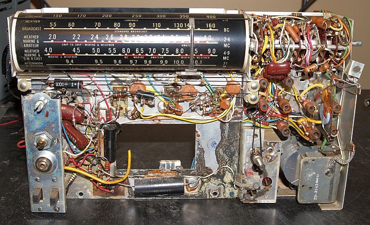
Below is a picture of the other side of the radio chassis as received. The corrosion is not as bad on this side.
As one would expect, the radio did not play. But I did not have the heart to throw it away or sell it for parts. I decided to attempt to fix it if possible. There were several bad transistors that included the AM/SW oscillator transistor, the first audio transistor, and the two output transistors. I began with injecting an IF signal in each stage and discovered an open winding in one coil of the second 455 kHz AM/SW IF. DC power goes through that coil and through the 10.7 MHz FM IF transformer. I jumpered a resistor across that open winding and was able to get the FM band working.
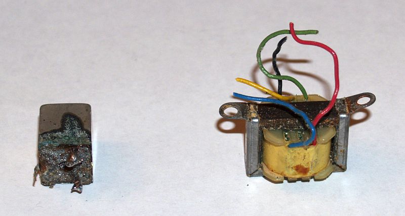
However, the audio was intermittant. I thought the transistor sockets for several transistors in the audio stage were bad because of corrosion and I replaced them. However, that did not totally cure the intermittant problem. I finally traced the problem to to the interstage audio transformer whose primary winding eventually opened. I replaced it with a Hammond No. 145P audio transformer. That cured the intermittant audio.
I had to replace the one open circuit 455 kHz IF coil in order to make the AM/SW bands work. I replaced the defective part with a Xicon AM 20k-6k 3rd IF coil. Because this coil is much smaller than the origianl one, I had to make two brass brackets to solder to the coil shield and screw to the chassis using the existing holes in the chassis that the tabs of the original coil were mounted and soldered to the chassis. Because the original coil was soldered to the chassis and I could not get sufficint heat in there to unsolder it, I used a Dremel tool to grind out the solder to remove the old coil. I oriented the new coil so that its tuning slug could be accessed through the hole in the chassis in which the original coil was mounted. This arrangement works well. Below are two pictures of the new IF coil installed.
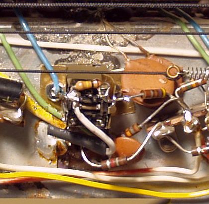
Because the coil was not an exact match to the original, that particular AM IF stage tended to oscillate. I placed a 100k-ohm resistor across the coil to reduce its Q and the oscillations stopped without adversely affecting its overall gain. You can see that resistor on the top of the coil in the first picture above.
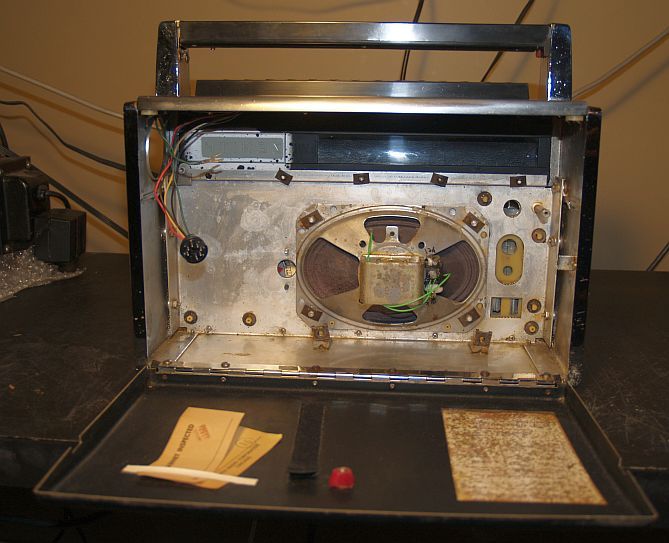
Below is a picture of the inside of the enclosure after I cleaned it and repaired the speaker.
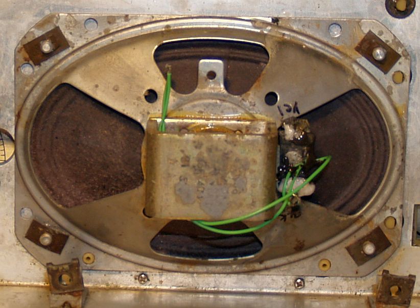
The corrosion discentegrated the pasteboard to which the speaker tabs were mounted. In addition, the wire connectors from the chassis to the tabs were permanently corroded to those tabs and the only way to disconnect the chassis from the speaker was to cut the wires. However, the speaker was good and works! I soldered new wires to the reminants of the speaker tabs and used JB Weld to securely fasten the wires to the speaker so that I would not break the fragile wires to the speaker voice coil. You can see the speaker repair in the picture below.
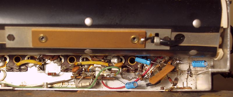
After all of this, the audio had low volume and sounded "mushy." I replaced all of the electrolytic capacitors and that fixed the problem. Below are pictures of the replacement capacitors installed.

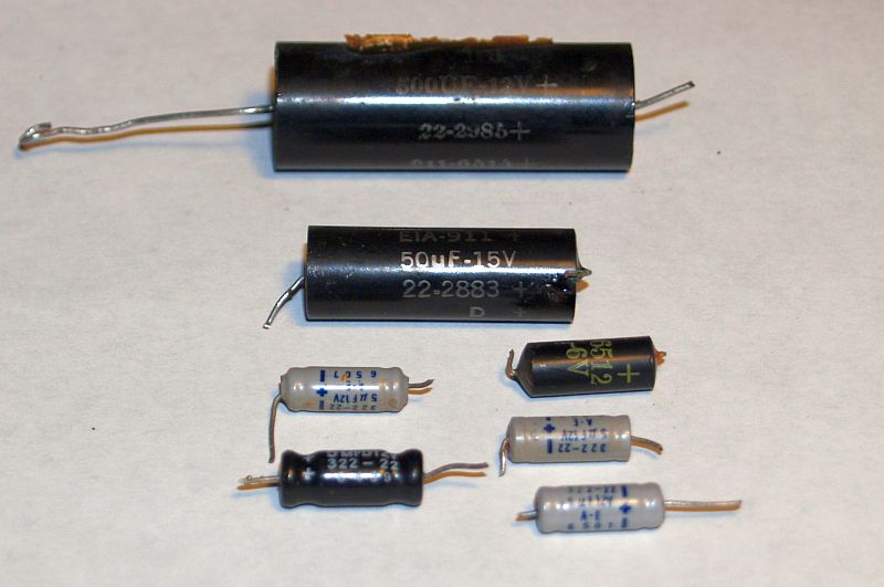
Below is a picture of the capacitors that were replaced.
Below is a picture of the IF coil and the audio interstage transformer that were replaced.
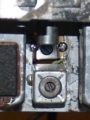
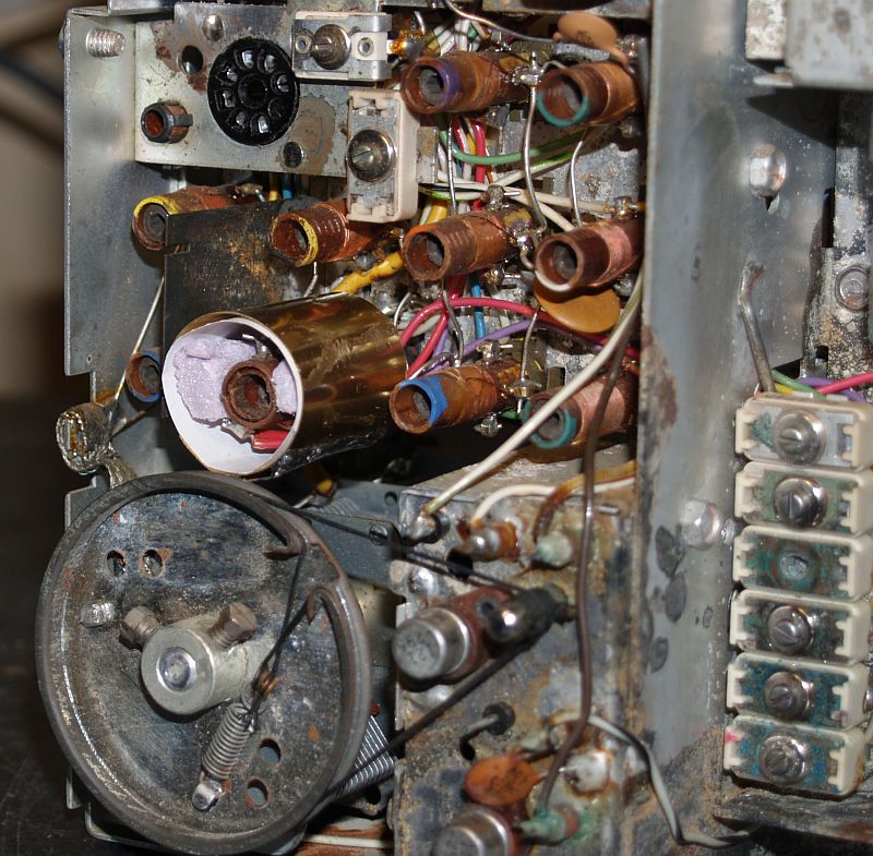
Now, all of the bands had good audio and volume except for the lower end of the AM band. I traced that problem to the mixer tuned circuit resonating too low in frequency. Unfortunately the ferrite tuning slug in the coil was stuck. I tried heating the coil and slug but I could not make it budge. I finally increased its resonant frequency by fabricaing a brass sleeve and mounting it over the AM mixer coil as shown in the pictures below. This fix brought the resonant frequency into proper tune and the AM sensitivy is now comparable to the "good" Zenith Royal 3000 discussed above.
The new audio interstage transformer and the new transistor sockets mounted on brass brackets can also be seen on the right-hand side of the picture above.
The audio driver stage tended to oscillate - only when operating on the FM band. And it oscillated only when the volume was moderately high. And the audio had some distortion. I fixed that problem by installing a 475 pF capacitor from the base of the driver transistor to ground.
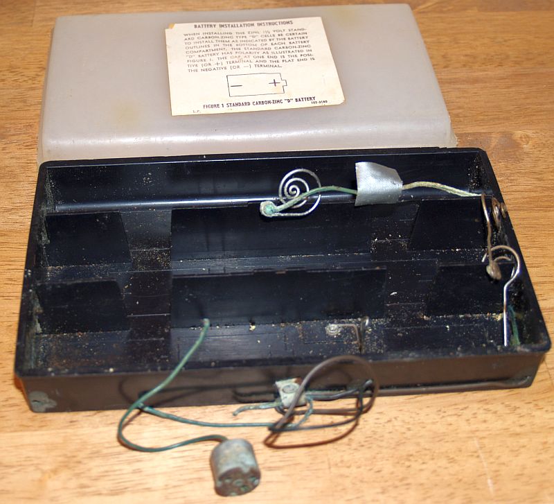
The battery box was extermely corroded as expected. Much of the internal connections had corroded away. However, the connection springs were good and present. The wires to the connector to the chassis had corroded, but the connector itself is restorable. I have not yet restored the battery box. Below is a picture of the corroded battery box.
I was able to clean up the corroded radio to make its appearance presentable. The results of this restoration are shown below.
Some of the chrome paint originally plated to the plastic is gone in several places as can be seen below. In addition, some of the silver paint on the speaker grill is thin as can be seen as "yellow" places in the picture below.
Some corrosion is still evident on the top as seen below.
Th corosion is still quite evident on the bottom as seen the picture below.
After all of this, the radio now does play quite well and does not look too bad.