The dimensions of the television are:
32 1/4 inches high
16 7/8 inches wide
19 1/2 inches deep including the metal back plate
The televison weighs about 100 lbs including the cabinet. The bakelite cabinet by itself weighs about 35 lbs.I understand the cabinet was the largest bakelite molding ever cast.
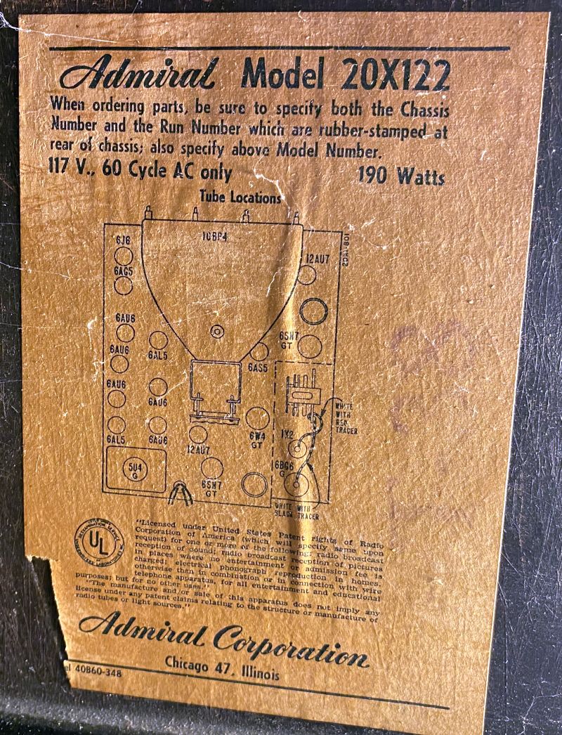
Below is a picture of the model and tube layout tag inside the cabinet.
The controls on the front panel include:
Horizontal Hold Control/Vertical Hold Control
Contrast Control/Brightness Control
Off Volume Control/Focus Control
Channel Selector Switch/Sharp (Fine) Tuning Control
The adjustments on the rear of the receiver include:
Horizontal Locking Range
Horizontal Drive
Horizontal Size
Vertical Linearity
Height
Horizontal Frequency
Horizontal Linearity
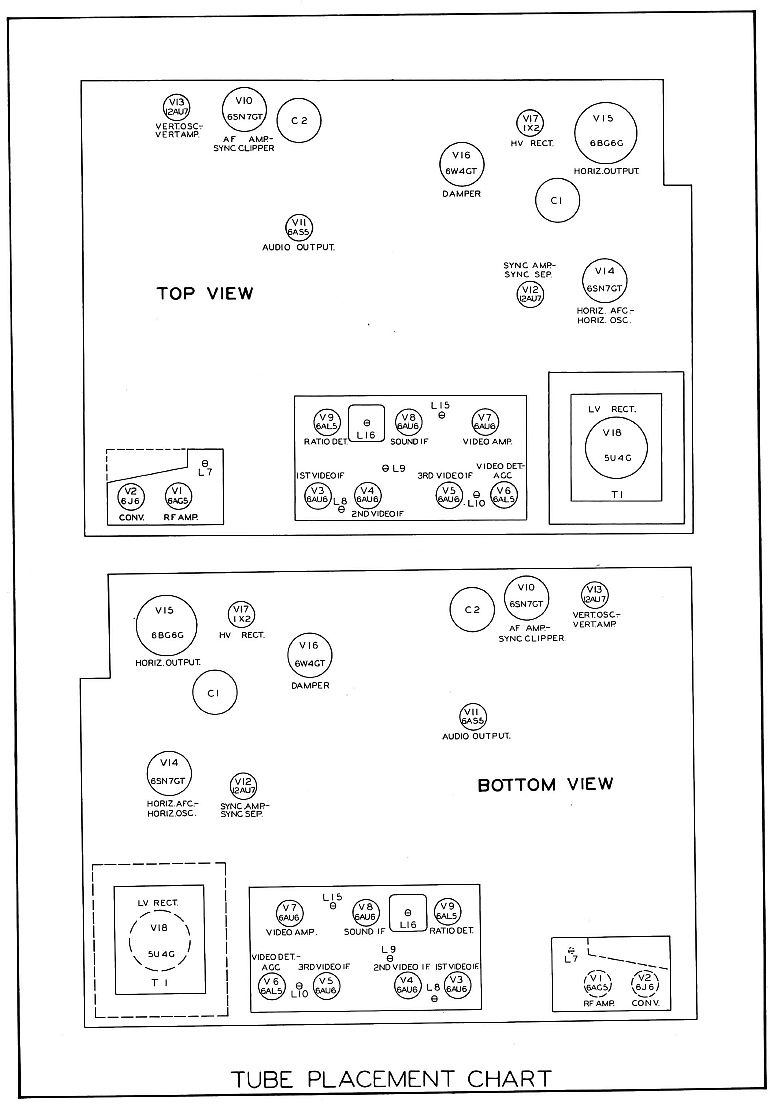
There is also a centering lever on the focus coil, the extension of which is missing on my television. The picture below shows the tube layout as depicted in SAMS Photofact Folder 1 of Set 100.
Below are pictures of the television when I received it. Note that the television has the original metal back cover that is often missing.
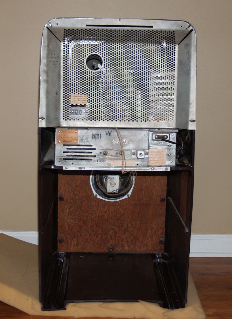


The cabinet was in good good shape with what appears to be places where the sunlight faded the bakelite. Below is a picture of the rear of the television with the metal back cover removed.
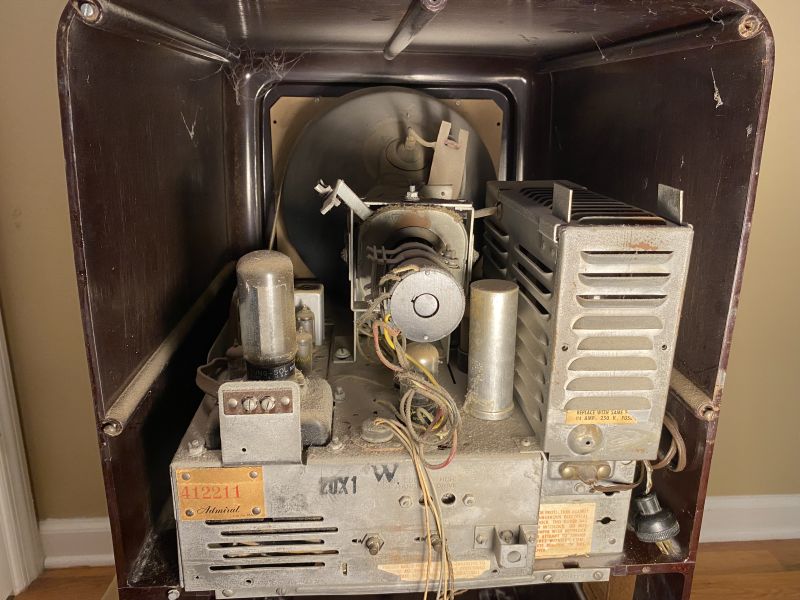

As you can see, the television looks in good shape; however, the chassis is extremely dusty and there are several spider webs about.
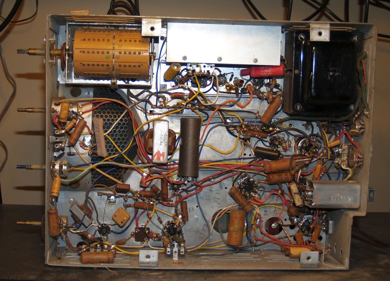
The picture below shows the the chassis when removed from the cabinet.

Everything looks in good shape except it quite dusty. There are thick layers of dust on everything.
A picture of the side of the side of the chassis is shown below.

The front of the chassis is shown below.
The bottom of the chassis before restoration is shown below.

As you can see, no restoration had been done to the television as all of the original wax paper capacitors are all present and many covered with dust.
Below are pictures of the original high-voltage cage with its protective cover removed.
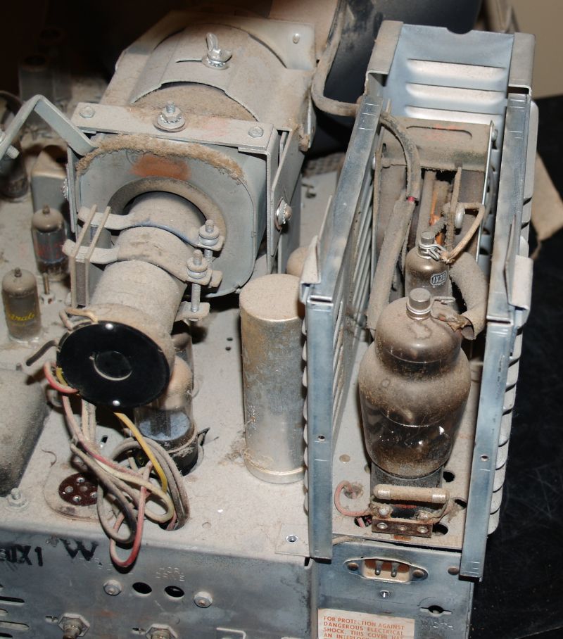
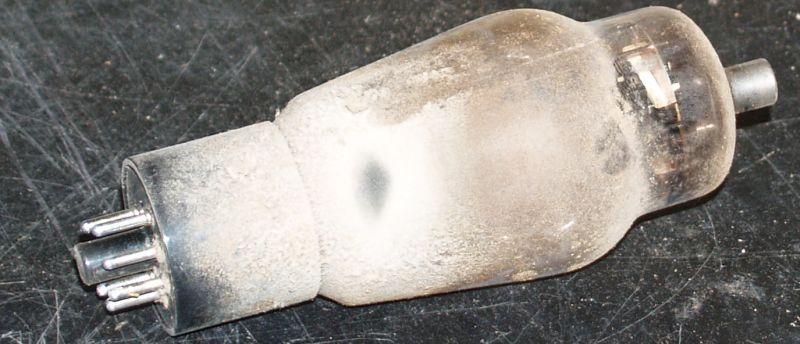
Note how dusty the the tubes are. Below is a picture of the 6BG6G horizontal output tube removed from its socket. It is covered with dust.
If I powered up the television with all of the dust present, I suspect there would be some arcing in the high voltage cage. Below is a picture of the high voltage cage after cleaning the cage and tubes of the dust.

Below is a picture of the speaker after removal from the cabinet. Note how dusty it is. However, the speaker is in good shape and it it works.

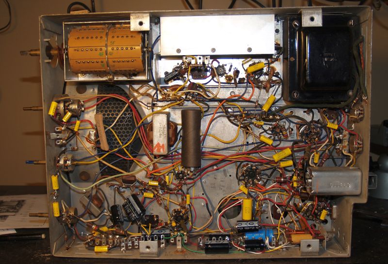
Below is a picture of the underside of the chassis after cleaning. I used a small hobby paint brush and a small air compressor to clean the dust from the components.
I did not attempt to power up the television until I replaced all of the capacitors. Doing so would be a futile effort because of the high potential for defective capacitors and the complexity of the circuitry.
Below is a picture of the bottom of the chassis after I replaced all of the wax paper, other solid capacitors, and electrolytic capacitors. The television has two multi-element electrolytic capacitors in cylindrical cans mounted on the top of the chassis and one insulated can on the underside. These capacitors are for power supply filtering and bypass/decoupling in several circuits. I replaced all of them with modern and much physically-smaller capacitors. I added terminal strips using existing holes in the chassis to mount the new electrolytic capacitors.
I did not place those new electrolytic capacitors in exactly the same physical location as the originals - the smaller packages allowed them in many cases to be placed closer to the circuits they were connected to. However, the original capacitor terminals were also used as tie points, so I had to be careful to maintain those connections when disconnecting them from the original capacitors. The picture below shows the underside of the chassis after replacement of all of the capacitors,and in a few cases, replacement of out-of-tolerance resistors.
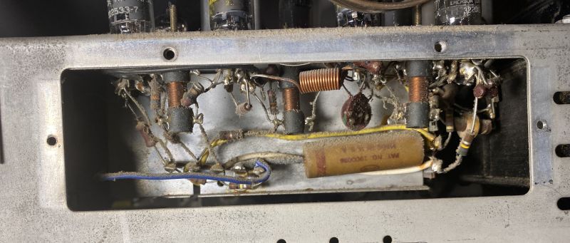
There was one wax paper capacitor underneath the metal cover at the top center of the picture. This cover is beneath the Intermediate Frequency (IF) strip. The capacitor is in the automatic gain control (AGC) circuit and establishes the AGC time constant. Pictures of the bottom of the IF strip without the cover are shown below.

The new replacement AGC capacitor is shown below.

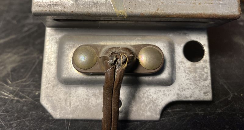
The insulation on the original power cord was hard and cracking all along its length. The insulation was also absent where the cord joins its safety plug end on the back of the chassis as shown below.
I cut most of the old cord off and covered the short wire length at the safety plug with heat shrink tubing as shown below.
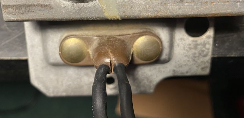
Note the slit I cut into the safety plug between the two wires. I cut this slit to allow larger heat shrink tubing to fit over the repaired wire and part of the safey plug. I soldered a new brown lamp cord to the original repaired wires and applied heat shring tubing over the soldered joints. Then I placed the larger heat shrink tubing over the two wires and the plug and applied epoxy to the tubing and plug to ensure the tubing will not slip off the safety plug and thus take any strain off the wires. The epoxy is shown below.

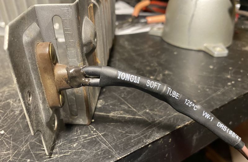
I then placed a larger heak shring tube over the two-wire assembly as shown below.
Finally I placed another larger heat shrink over the two-wire assembly and over the safety plug base and epoxied the heat shrink to the safety plug base as shown below.
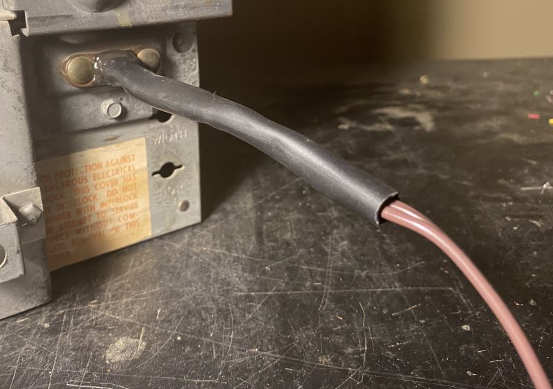
Although the power cord at the safety plug is now stiff and not very flexible, at least it should be fairly reliable.
I reused the original power plug that was attached to the old wiring. The original plug with the new lamp cord wire is shown below.

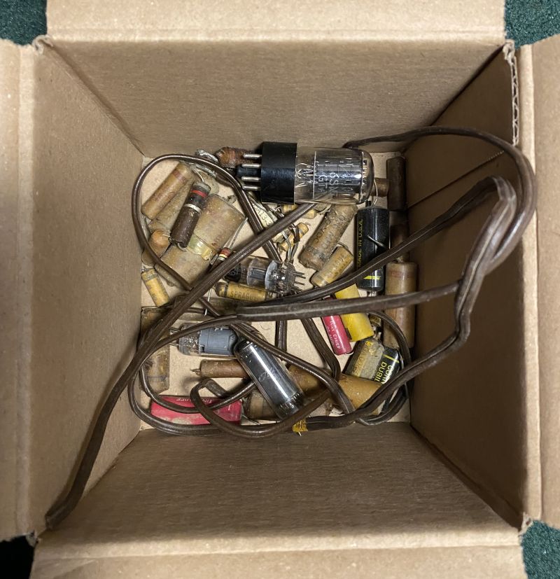
Below is a picture of a box containing the original resistors, capacitors, power cord, and vacuum tubes that I replaced.
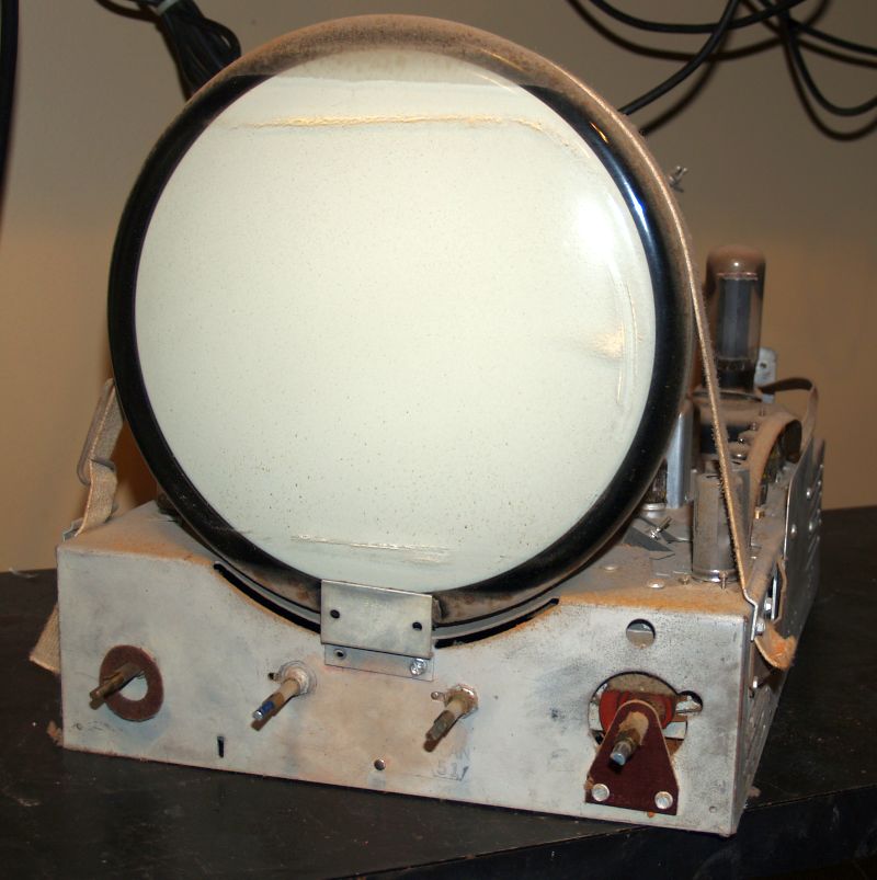
After replacing all of the capacitors,the power cord, and tubes that tested weak, I applied power slowly using a variable transformer. After a period of warm-up, a raster appeared on the cathode ray tube (CRT). The raster is shown below.
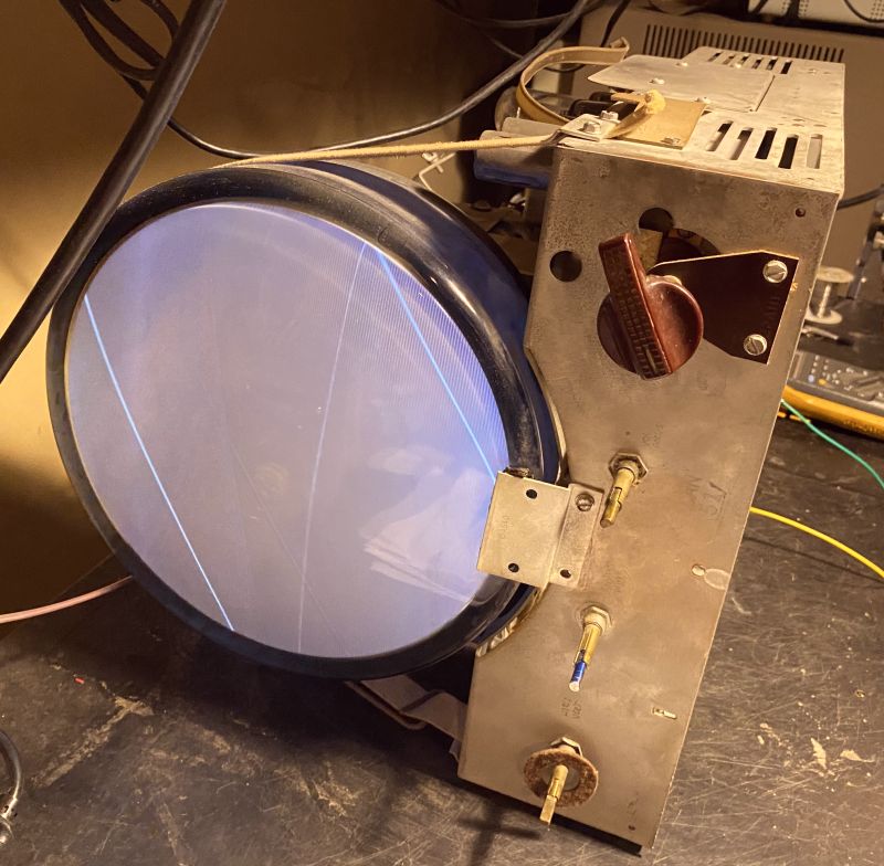
This test confirms the picture tube CRT is good. Previously, I tested the CRT with my CRT tester and it indicated the CRT is good, but possibly weak. You can read about the CRT test here.
After success with power up, I used my B&K Television Analyst to inject an RF signal and the image received is shown below.

All of these tests indicate the television is working and quite usable with some adjustments.
During a repair sometime in the past, a 1-Meg ohm resistor was apparently used to replace a 2.2-Meg ohm resistor in series with the vertical height control. I replaced it with the correct value and the vertical height (and subsequently the vertical linearity)improved to cover most of the vertical screen. I added a 0.01 uF in parallel with the flyback transformer horizontal output to slightly extend the horizonal width to cover most of the screen. The larger 12-in diameter CRTs use a 0.0135 uF in this place, but the smaller 10-in CRTs do not use any capacitor.
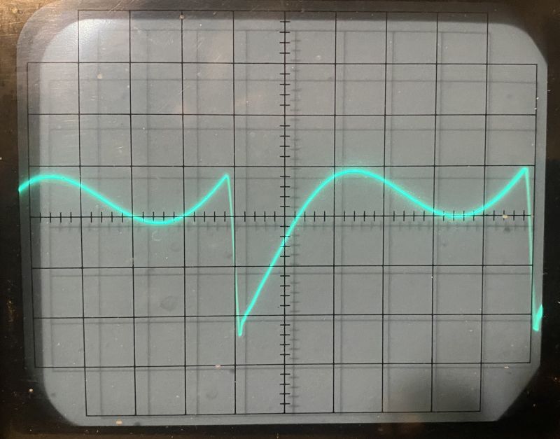
I adjusted the horizontal lock-in, frequency, and drive per the specifications. The picture below shows the horizontal sync properly adjusted with the peaks at equal amplitude.
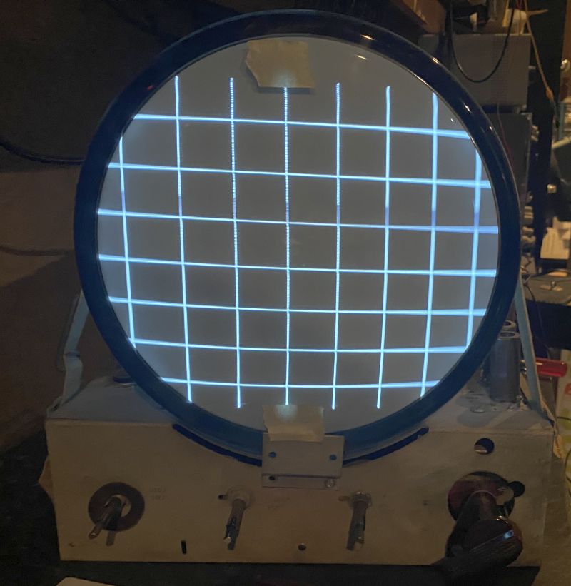
The picture below shows a crosshatch pattern. The linearity and size look good.
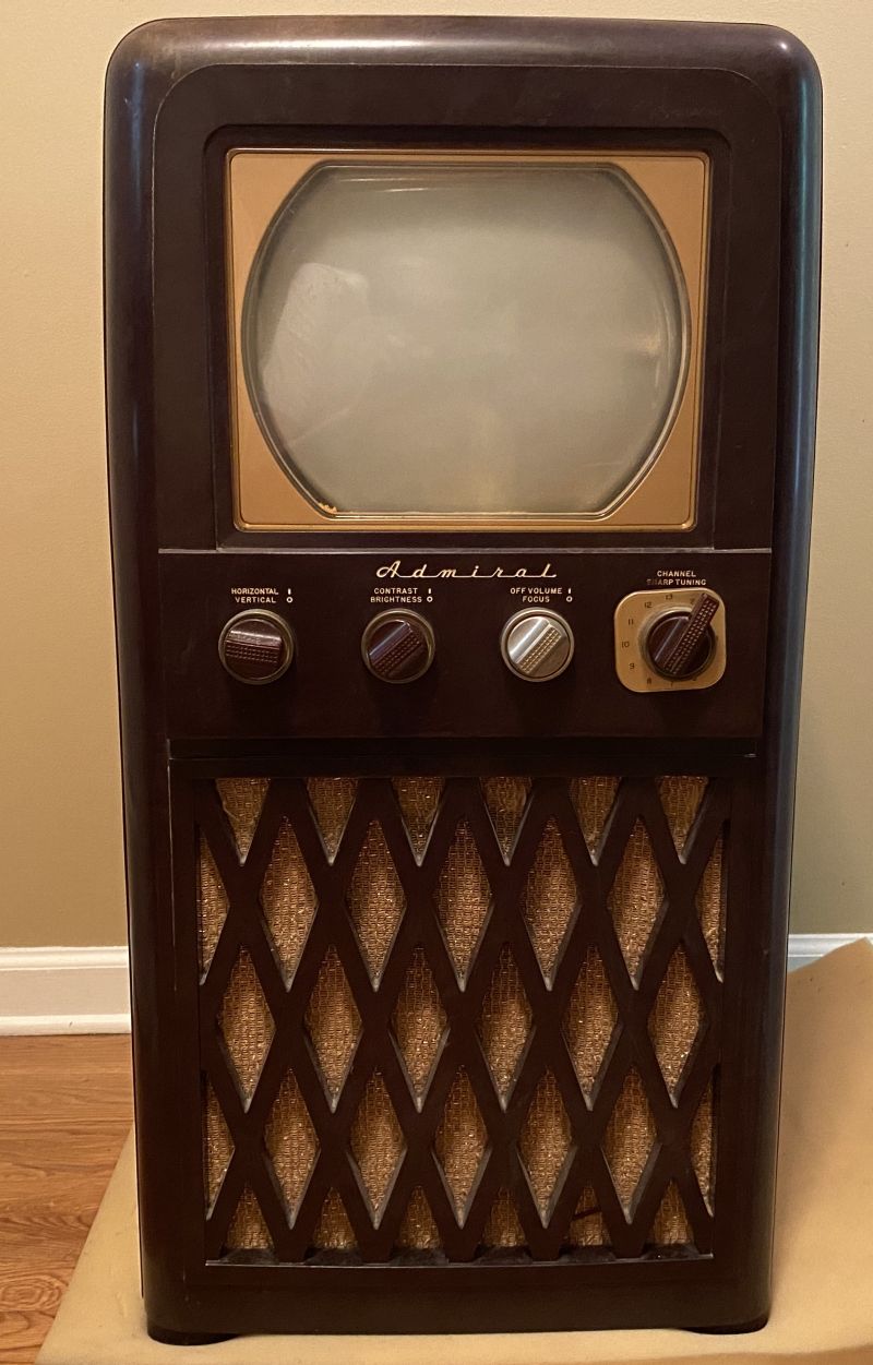
The bakelite cabinet had no cracks and had minimal scratches, but it has some lighter spots presumably caused by sun exposure. I used Novus #2 Fine Scratch Remover and brown shoe polish to make the cabinet look like new. The refinished cabinet is shown below.

As you can see, the cabinet looks almost like new.
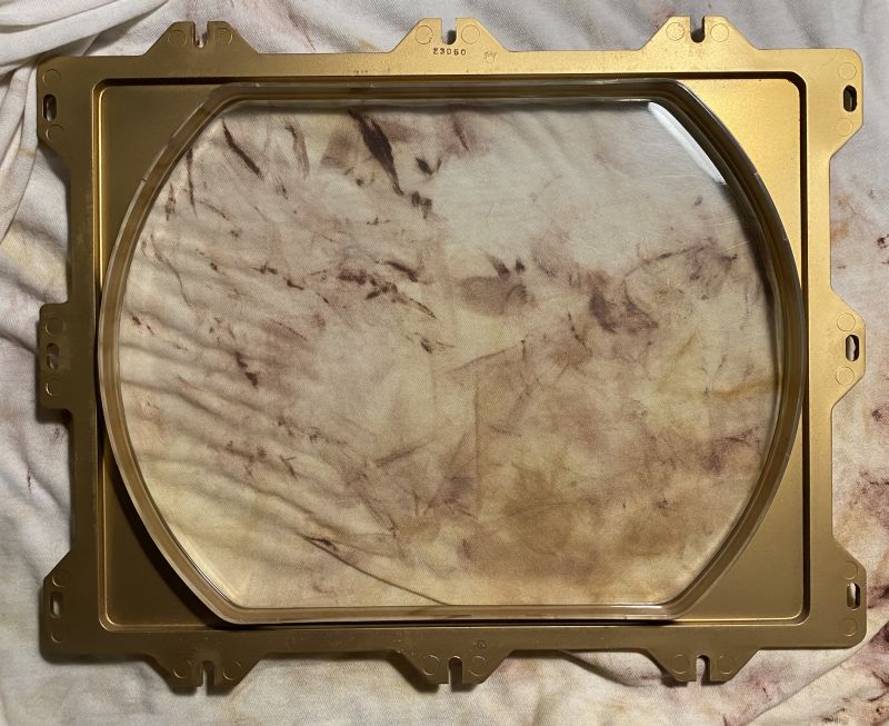
I used Novus #2 Fine Scratch Remover to remove some scratches and cloudiness from the plastic escutcheon. The refurbished plastic escutcheon is shown below.
The original orange-colored "surround" encircling the clear opening in the escutcheon had hardened and crumbled to pieces over time. The reminants of the suround is shown below.
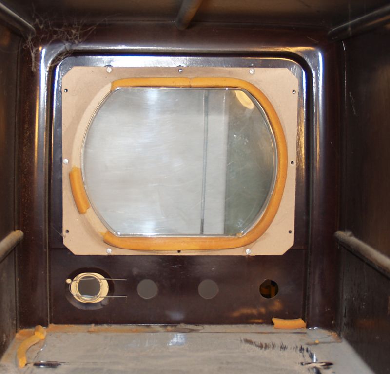
I cleaned off the old surround from the cardboard on which it was glued. The cardboard mount is shown below.
I replaced the original surround with 1/2 in diameter "backer rod" used to seal gaps and joints in houses and buildings. The result is shown below.

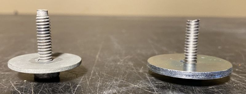
Two of the bolts that hold the chassis to the shelf in the cabinet were missing. I made two from a 1/4-20 stainless steel bolt. I used a 1/4 x 1-1/2 in. fender washer to replace the missing washers. A comparison of the original bolt and the replacement is shown below. The original bolt and washer is on the left in the picture.
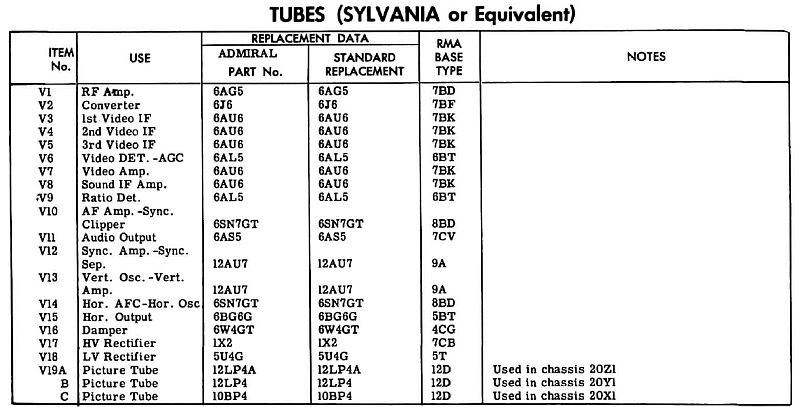
Tube Compliment
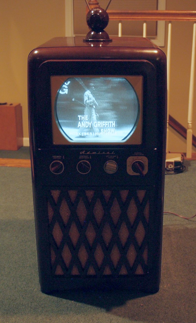
The television seems to work well. I have a Blonder Tongue BAVM-860SAW agile modulator operating on Channel 12 that takes video and audio from a Zenith HDTV-to-analog TV converter box and transmits it across the room and the television receives this transmission via the rabbit ears antenna on top of the set. The agile modulator is shown below.

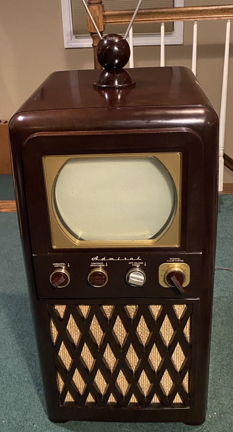
The rabbit ears antenna on top of the television is vintage, too. A picture of the antenna is shown below.

The rabbit ears indoor antenna is manufactured by Radion Manufacturing Corp, 1137 Milwaukee Ave, Chicago, Ill. Below is a picture of the bakelite base of the antenna.
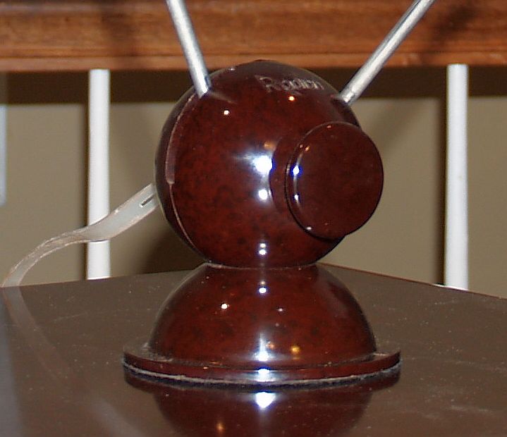
The knob on the base can be turned so that you untighten it and adjust the angle of the two telescoping rabbit ears and then retighten it to keep them in place. Below is an advertisement for this antenna in a 1949 edition of the Radio Television Journal. The copyright on the advertisement (1949) is around the same year the television was made. Note the the list price of the antenna in 1949 was $6.95.

Below is a picture of the television operating and receiving a vintage program.
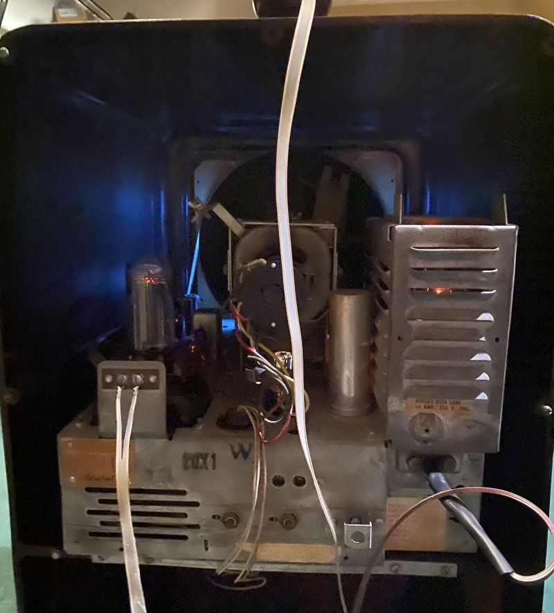
Below is a picture of the rear of the television with it operating.
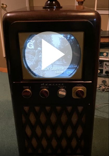
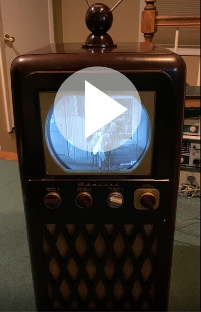
Below are two videos of the television operating and receiving a vintage program ("The Andy Griffith Show").
Below is an advertisement for this television. The advertisement is by a furntiture store in Minneapolis, Minnesota.

Note that the television sold for $229.95 in 1948/1949, quite expensive for that time, but claimed to be the lowest price ever for a full size television console. If you look closely, I beleive you can see that federal tax on the purchase is $1.85.