Most of my equipment is older; some of it is vintage. The newer equipment is mainly associated with 2 meter FM mobile operation.
Below are photos of some of my equipment.
1969 Drake 4B Line HF Equipment
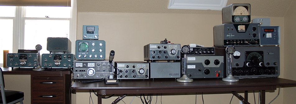
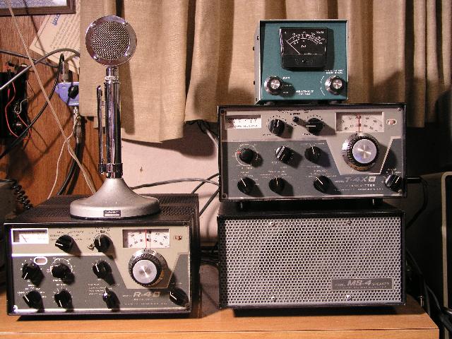
Below is a picture of my vintage Drake 4B Series HF Station. The station includes an R-4B receiver, an MS-4 speaker, and a T-4XB transmitter. The station also includes an Astatic D-104 microphone. The AC-4 power supply for the transmitter is mounted in the rear of the speaker. The transmitter is in excellent shape with minimal rust on the copper-plated chassis. However, the receiver has considerable rust on the copper-plated chassis. I had to replace the filter capacitors and several tubes in the receiver to make it work properly. The receiver also has one incorrect knob. This station works well now. I have a 75 meter dipole in my back yard.
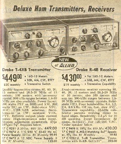
Below is part of page 205 from the 1969 Allied Radio Catalog showing the Drake station above. As seen in the picture below, they were new at Allied in 1969. Note the T-4XB transmitter sold for $449 and its power supply sold for $99.95. The R-4B sold for $430 and the matching speaker that houses the transmitter power supply sold for $19.95. These items sell today in 2007 for close to that amount.
Amperex 8802/3-500Z
Amperex 8163
Eimac 3-400Z
Eimac 3-500Z
Two tubes are required.
The amplifier has the following specifications:
1000 dc on CW, AM, and RTTY |
75 W on CW, AM, and RTTY |
3000 W forward, +/- 5% of reading +30 W |
120 Vac 50-60 Hz, 30 A |
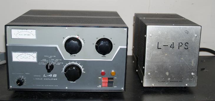
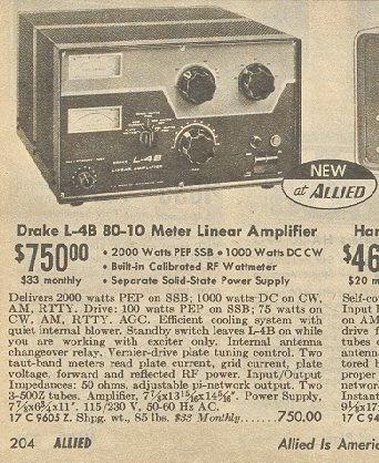
Below is part of page 204 from the 1969 Allied Radio Catalog showing the Drake L-4B. As seen in the picture below, it was new at Allied in 1969. Note the L-4B sold for $750. The L-4B sells in 2007 for nearly that amount.
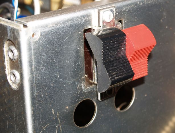
After I had this amplifier for several years, the on/off switch became stuck "on." Even though the rocker on the front panel would move, the switch contacts remained closed and the only way to turn off the amplifier was to unplug it. This is a fairly common problem as over time the switch contacts develop little spurs that eventually fuze together. Every time the switch closes, it bounces a little bit and an electrical arc forms across the switch contacts and eventually the spurs become long enough to fuze together. That is exactly what happend to mine. This switch is no longer available. Fortunately there is an individual that sells a replacement kit on eBay and I purchased one from him. This kit replaces the contact portion of the switch and reuses the plastic rocker part of the switch. Repair requires replacing the original contact portion with the new contact portion. The kit is actually two double throw switches whereas the original switch is one double throw and one single throw switch. Replacing the switch requires removing the front panel of the amplifier. To remove the front panel, the all knobs must be removed and the two neon indicator lamps must be unsoldered from the chassis.
The picture below shows the switch as orignally installed.
The picture below shows how the switch is installed when the cover is removed.
The picture below shows the old switch disassembled with both contacts in their original position.
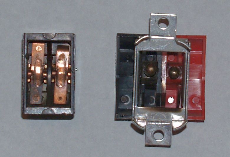
You can see the dark discoloration of the left-side contacts. These contacts are the CW/Tune-SSB switch. Below is a picture of the old switch with the contact portion removed from the switch assembly.

You can see the contacts for the CW/Tune-SSB switch on the left are burnt but the contacts on the right are significantly pitted. The contacts on the right are the ON/OFF switch.
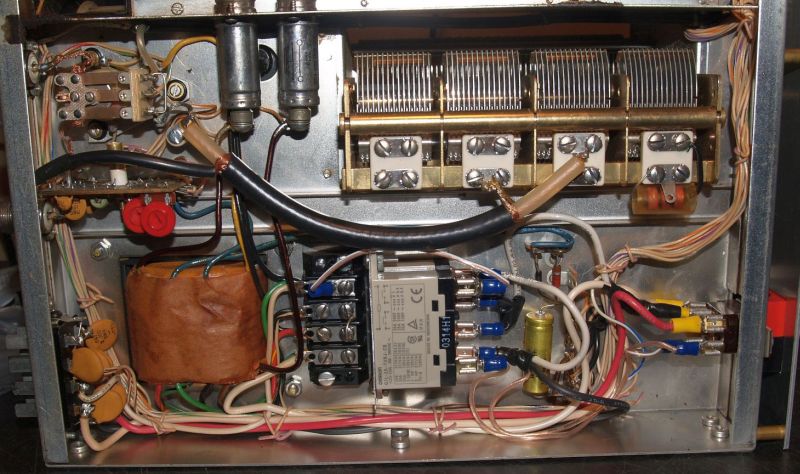
To save wear and tear on the new switch, I installed a 240-V relay that the switch now activates. The coil of the relay requires a lot less current than the 15A the amplifier requires when operating on 240VAC. Thus the switch should last a lot longer. Of course, this means the amplifier must operate on 240 VAC, and cannot operate on 120VAC unless the relay is replaced with a 120VAC version and the amplifier rewired accordingly.
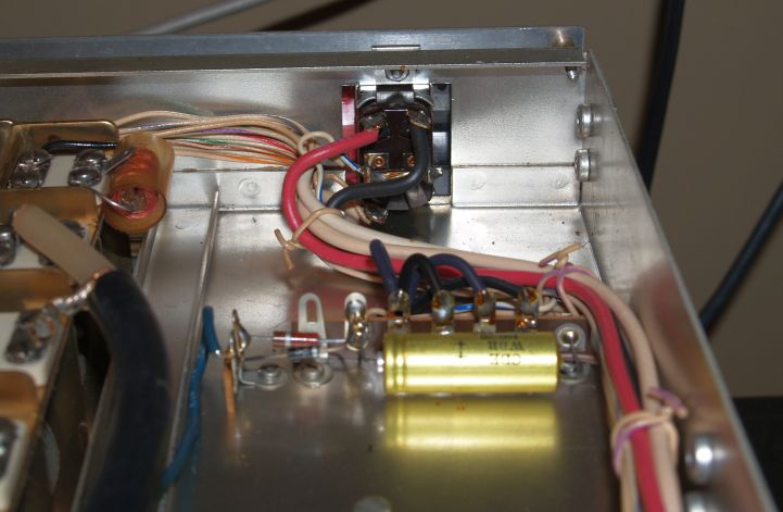
The relay I used is an OMRON ELECTRONIC COMPONENTS, G7L-2A-TUB-J-CB-AC200/240,POWER RELAY DPST-NO 240VAC,25A,BRACKET relay. The Newark electronics number is 35K4543. I paralleled the normally-open contacts (rated at 25A each). I made a custom L-shaped bracket out of aluminum to mount the relay. One section of the L-bracket mounts under the extant terminal strip in the amplifier and the two screws that mount the terminal strip also holds the bracket in place. I used push-on lugs on all the wires so that the relay (and switch) can be easily removed if need be. Below is a picture of the relay and new switch installation.
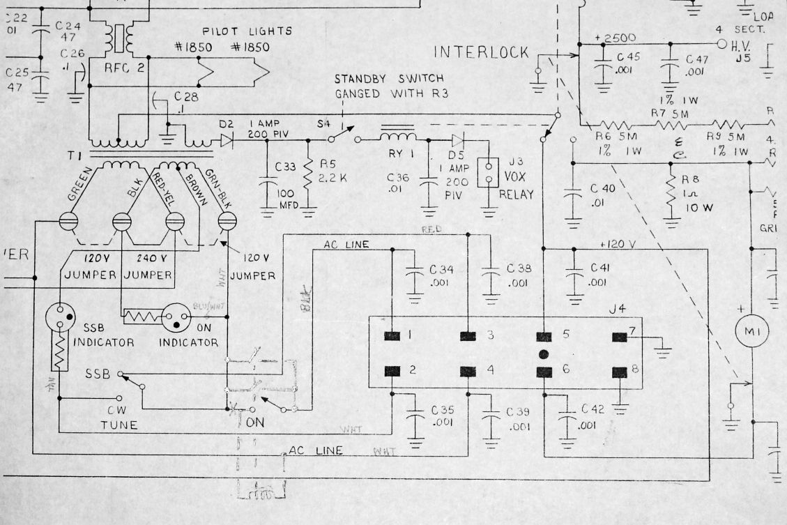
Inclusion of the relay requires rewiring the amplifier from the original schematic. The partial schematic below shows how the relay was added in the circuit.
I also replaced the two neon indicator lamps. These are still available from Newark Electronics. They are CHICAGO MINIATURE LIGHTING 1050C1 LAMP,INDICATOR,NEON,RED,125V,Newark number 18M7896 and CHICAGO MINIATURE LIGHTING 1050C3 LAMP,INDICATOR,NEON,AMBER,125V,Newark number 18M7898. The amplifier is now back in working order.
1968 Heathkit SB Series HF Equipment
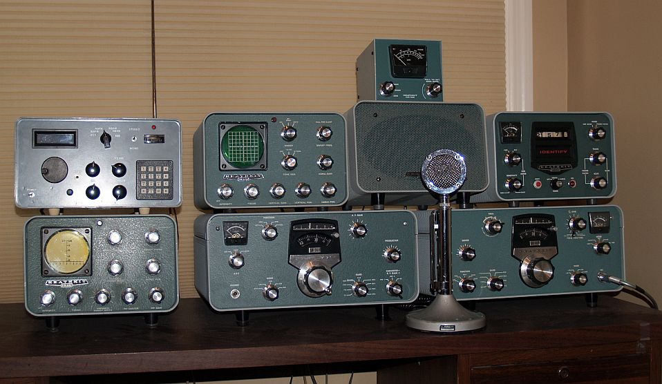
Below is a picture of my vintage Heathkit SB series SSB HF station. The station includes a Heathkit SB-301 Receiver, a Heathkit SB-401 Transmitter, a Heathkit HM-102 Wattmeter/VSWR meter, a Heathkit SB-600 Speaker, a Heathkit SB-610 station monitor, a Heathkit SB-620 Scanalyzer, a Heathkit SB-630 Station Console, and an Astatic D-104 microphone. The only piece of this equipment that I built from the original kit is the Wattmeter. I had to repair the reciever by rewinding the primary windings of the 75 and 40 meter antenna coils - the windings were both open and the receiver sensitivity on those bands was quite poor when I received it. I also had to align the receiver. After that, the receiver works well. The receiver has both the SSB and AM crystal filters installed - the CW filter is not installed. The transmitter worked well when I received it, so I did not have to make any repairs. I had to repair the station monitor by replacing the high voltage power transformer and filter capacitors. The SB-620 Scanalyzer worked when I reeived it. It is tuned to 455 kHz and not the 3.9 MHz IF of the Heathkit receiver. The SB-630 Station Console worked when I received it - even the motor-powered clock works! I did have to resolder the coupling capacitor in the phone patch circuit as it probably broke during shipping.
You can see more on the SB-610 station monitor by clicking here.
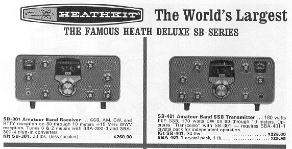
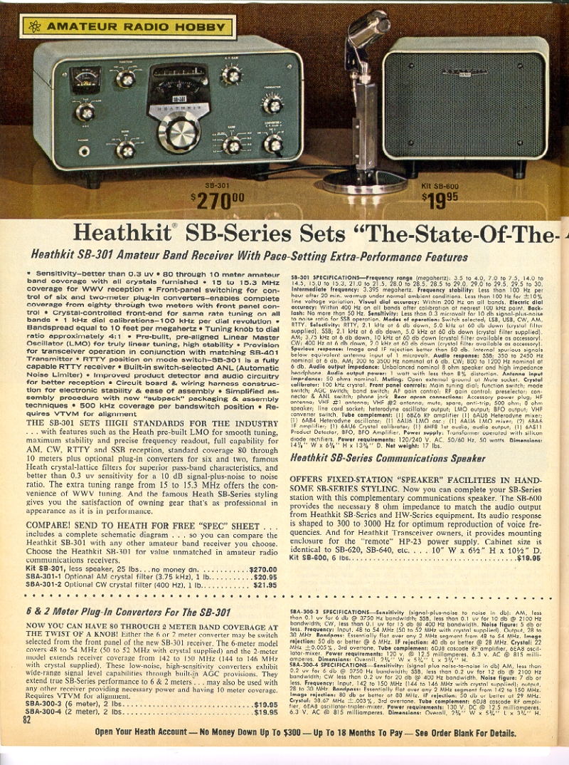
Below is an advertisement for the Heathkit SB-301 and SB-401 from the 1967 ARRL Radio Amateur's Handbook. Note the prices of this equipment in 1967 was relatively expensive.
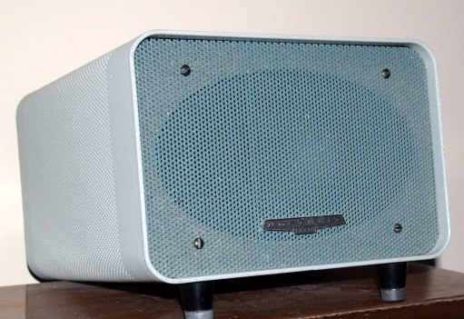
My SB-600 speaker is shown below.
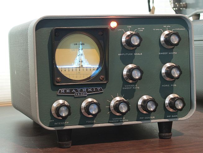
Below is a picture of the SB-620 Scanalyzer. The Scanalyzer is connected to the IF of my homemade Communications Receiver. The display on the Scanalyzer is showing a narrowband FM signal (actually the National Weather Service station). You can see the voice modulation on either side of the carrier (the large spike in the center).
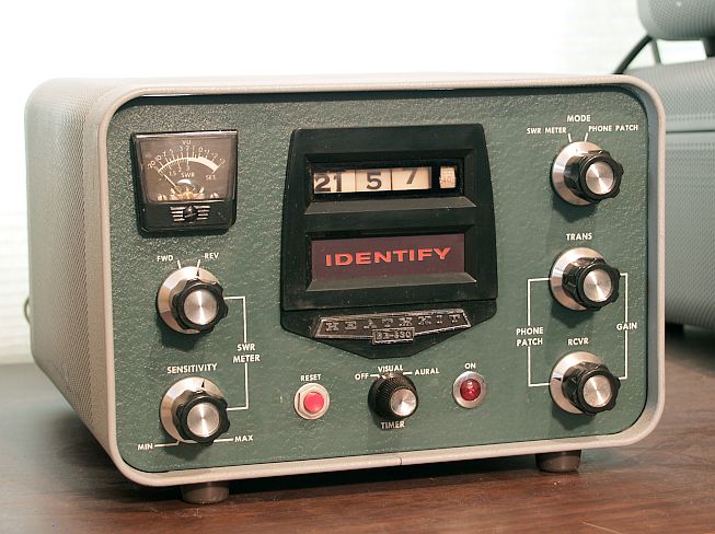
Below is a picture of the SB-630 Station Console.
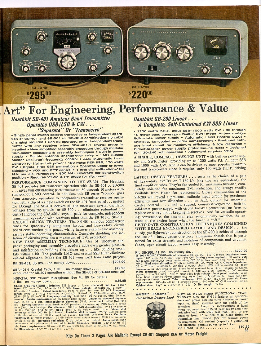
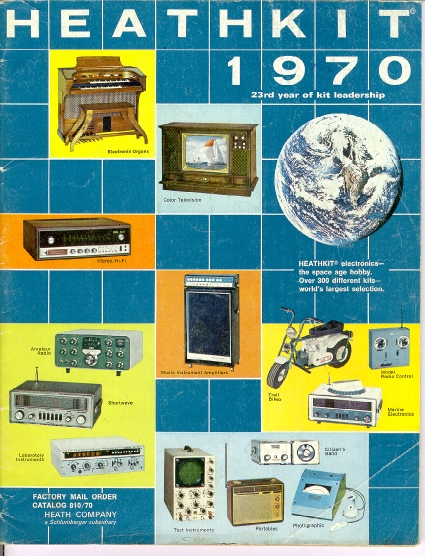
This amateur equipment was featured in a two-page color advertisement in the 1970 Heathkit catalog. Below are the two pages from this catalog featuring this equipment.
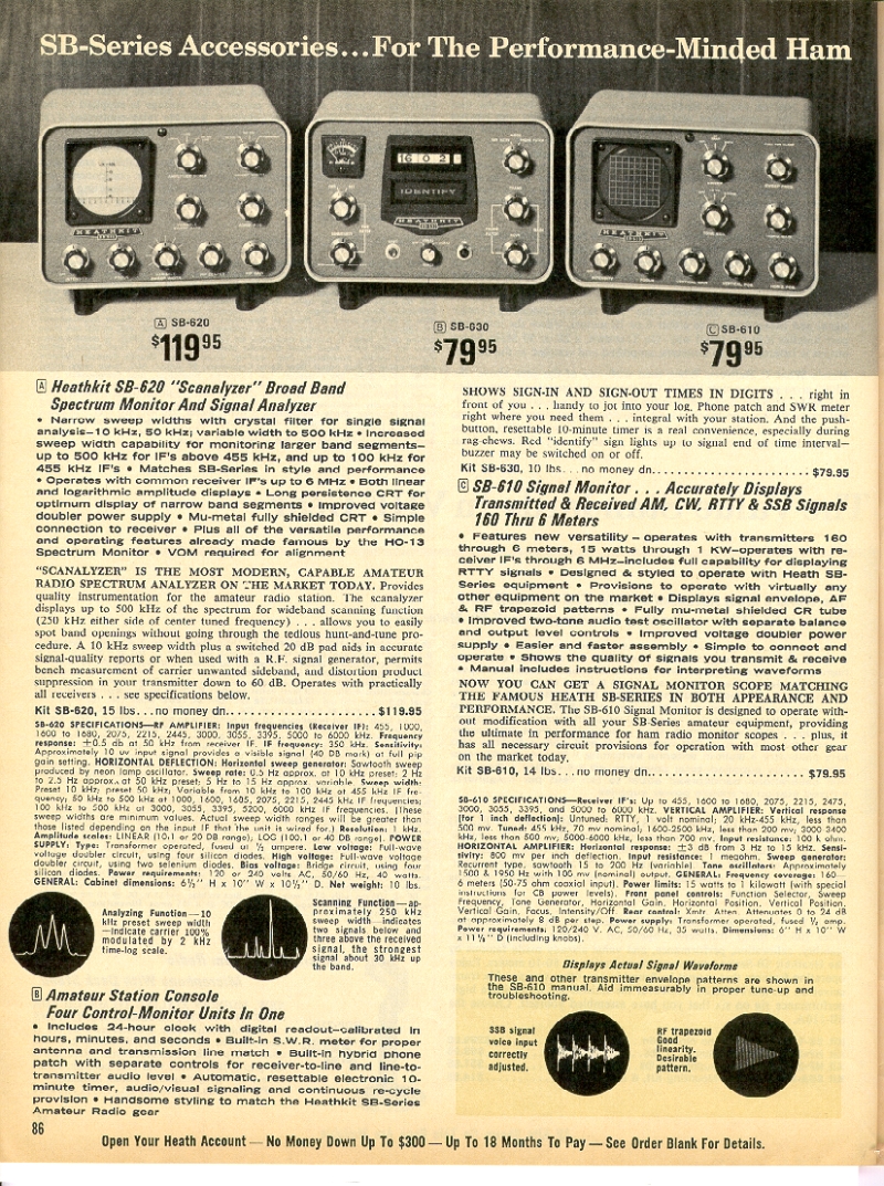
Below is page from the 1970 Heathkit catalog featuring the SB-610 monitor scope and two other accessories.
Below is the cover of the 1970 Heathkit Catalog.
Below is a picture of the Heathkit HM-102 HF Watt Meter. I built this watt meter in the late 1970's.
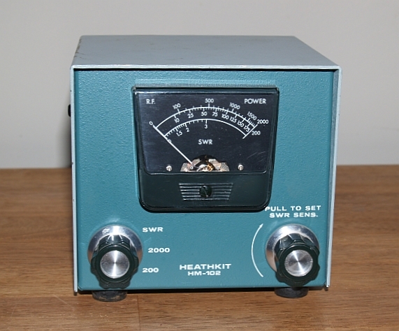
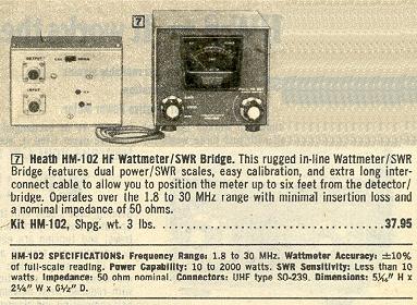
Here are the specifications and price of the watt meter from the Winter 1979 Heathkit catalog:
1960s Heathkit HF Equipment
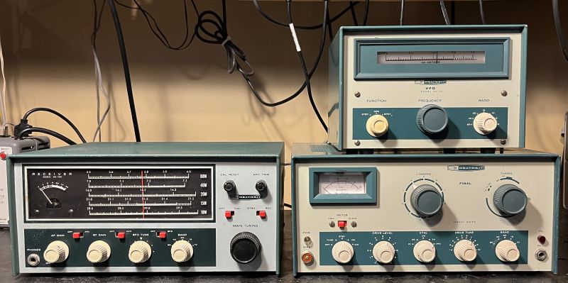
Below is a picture of the Heathkit DX-60 CW and AM transmitter, HG-10 VFO, and HR-10B receiver.
1958 Collins S-Line HF Equipment
Below is a picture of my vintage Collins S-Line HF station. As shown in the picture from top to bottom is a Collins 516F-2 power supply, Collins 75S-1 receiver, and a Collins 32S-1 transmitter. I use an Astatic D-104 microphone with this station. This equipment is vintage circa 1958 I believe. The transmitter has the factory installed ring diode balanced modulator,suggesting it is a later version as an earlier version had only a two-diode balanced modulator.
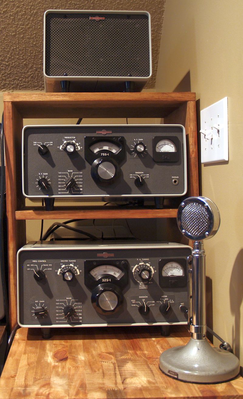
I did not purchase this station as a complete set; I purchased all three separately at three different times. I had to repair all three components, too. The receiver had a defective RF gain control potentiomenter. The potentiometer was broken in its center. The problem was not immediately evident as the receiver would work reasonably well, but the RF control would not control the gain as one would expect. I could not find an exact replacement, so I used one with a resistance value higher and placed a resistor in parallel to make the total resistance near the original value. The receiver works well.
The transmitter required more work. When I first powered it up, the plate current was not what the manual specified. Researching the internet suggested the cathode resistors associated with the finals may be out of tolerance and that proved to the the problem. I replaced all six 12-ohm cathode resistors and the plate curent reads correctly and the transmitter produces over 100 Watts output on 75 meters. The transmitter also had a defective 12AT7 VOX amplifier and a malfunctioning 6U8A VOX relay actuator cicuit (the tube tested good). Although I do not use VOX, the VOX relay actuator circuit must operate correctly to use the push-to-talk. I placed a 2.2 M-ohm from the grid of V11A to ground and the circuit operates correctly now.
The power supply had serious problems as I noted the fuse was blown. The power supply had been re-capped but the new capacitor placed in the negative bias circuit had too low of a working voltage and it shorted taking out the silicon rectifier diode, too. The original circuit had a selenium rectfier and the silicon diode has a lower voltage drop, making the capacitor working voltage to be even higher. I replaced the silicon diode and the capacitor (with a higher working voltage) and the power supply works correctly now, producing the correct voltages.
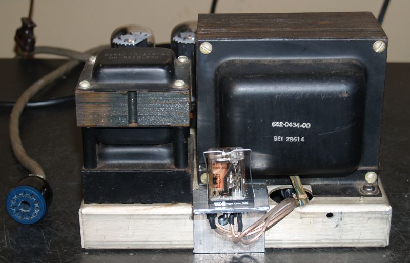
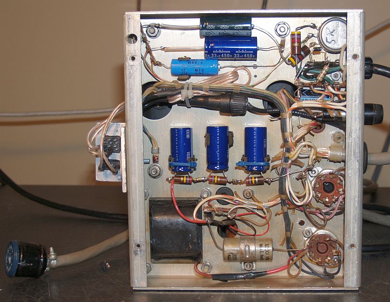
I also modified the power supply to insert a 110VAC relay to activate the power supply still using the on/off switch on the transmitter. That switch would be difficult to replace, so instead of running 4 Amps through that switch, with the relay, less than 7 mA runs through the switch to activate the relay coil. The larger current for the supply runs through the relay contacts. The pictures below show the relay modification installed in the power supply. I installed a fuse holder with a 1/2 Amp fuse under the chassis; this fuse is in series with the relay coil and the transmitter switch. The 4-Amp fuse for the power supply remains in the chassis-mounted fuse holder on the rear of the power supply.
Later on,I purchased a Collins 30L-1 linear amplifier at a hamfest (radio amateur convention). The linear is shown below. There was no room on my table, so I have it sitting on a wood planter beneath the table.
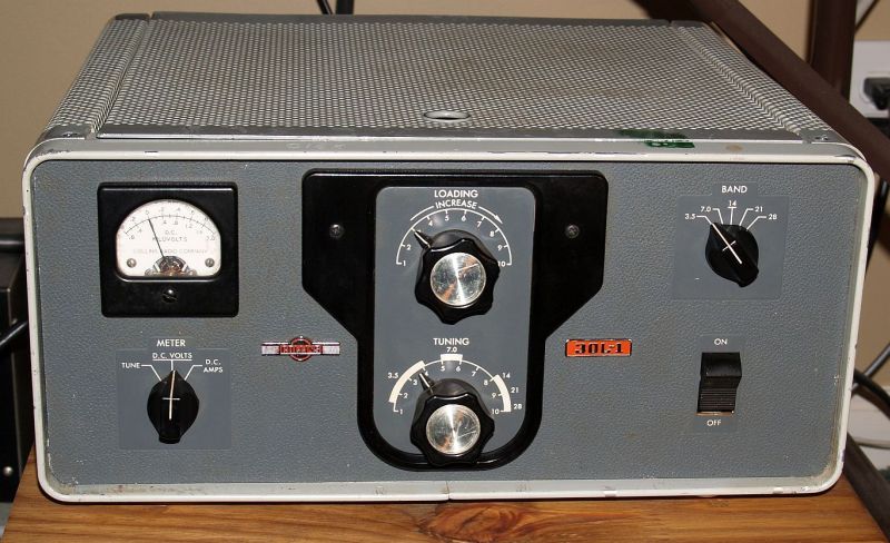
The amplifier worked when received; however the PIM nuts pressed into the chassis were missing. The nuts hold the screws that attach the feet and secure the chassis in the cabinet. The feet were also missing. In addition, a screw that held the front trim ring in place was also missing. And the ALC feedback was adjusted too high such that it significantly cut back the output power when used with my Collins 32S-1 exciter.
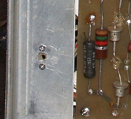
I replaced the PIM nuts with floating nut plates, part number MS21075L06, that is a MIL SPEC part. The nut plate uses a 6.32 screw. I mounted the nut plates to the chassis using #2-56 x 3/8" Flat Head Phillips Machine Screws. I used flat head screws in a countersunk hole to keep the bottom surface of the chassis flush. Below is a picture of one of the floating nut plates installed.
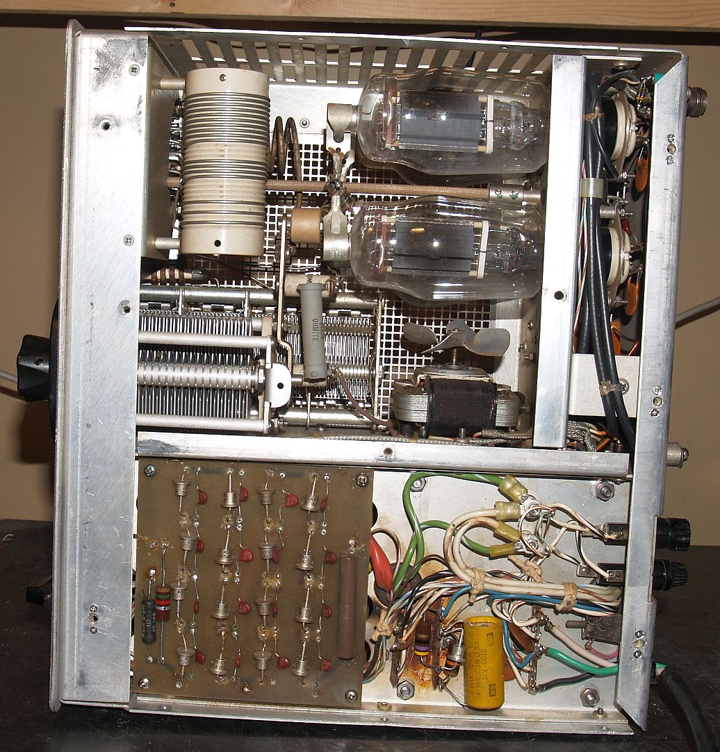
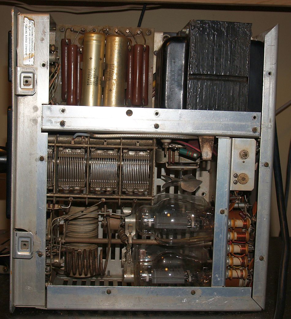
Below are pictures of the bottom and top of the amplifier chassis.
I purchased four rubber feet at a home improvement store and mounted them using stainless steel #6-32 screws � inch and � inch long, depending on where the feet were located.
Addressing the ALC issue revealed that the ALC in my Colling 32S-1 exciter was nto properly adjusted and the circuit had two components whose values had significanty increased. The slow decay 0.5 uF capacitor had doubled in value to 1 uF. And a 680k ohm resistor had increased to approximately 728k. I replaced the capacitor with a 0.47 uF and a paralleled a 10M across the resistor to produce an effective value of about 678k (I did not have the excact value handy, so this is a temporary fix). I cleaned the ALC zero potentiometer with De-oxit and zeroed the ALC circuit. The exciter seems to work as designed now. Then I adjusted the ALC feedback gain the 30L-1 linear so the output power is what would be expected.
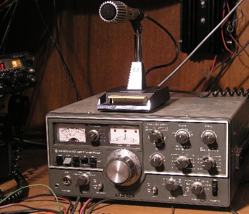
1976 Kenwood TS-520 HF Equipment
Below is a picture of my TS-520 HF transceiver. This is the first piece of amateur radio equipment I purchased. I have the matching MC-50 microphone and the matching SP-520 speaker.
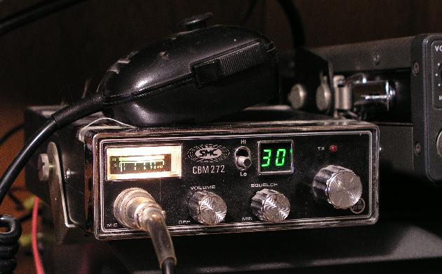
10 Meter FM
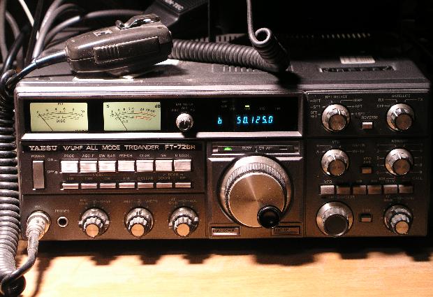
Yaesu FT-726R VHF/UHF Equipment
Ten-Tec Model 1260 6 Meter FM Transceiver
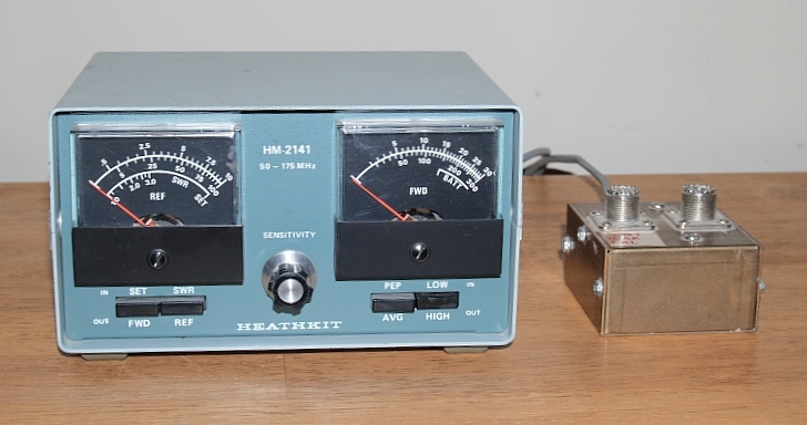
Heathkit Model HM-2141 VHF Dual Watt Meter
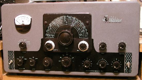
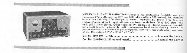
1957 Johnson Viking Valiant Transmitter
1.75 MHz to 2.0 MHz (160 m)
3.5 MHz to 4.0 MHz (80/75 m)
7.0 MHz to 7.42 MHz (40 m)
14.0 MHz to 14.85 MHz (20 m)
21.0 MHz to 21.6 MHz (15 m)
26.9 MHz to 27.36 MHz (11 m)
28.0 MHz to 29.7 MHz (10 m)
The final amplifier is rated as follows:
| Mode | Plate Power Input | RF Output |
| CW | 275 W | 200 W |
| AM | 200 W | 150 W |
This transmitter is quite large and heavy. It is 21 1/8 in wide, 17 3/8 in deep and 11 5/8 in high. It weighs 83 pounds.
Below is an advertisement for this transmitter from the 1957 ARRL Radio Amateur's Handbook. Note that is sold for $349.50 as a kit. It sells for about that now if it is working and in good cosmetic condition. The assembled version sold for $100 more.
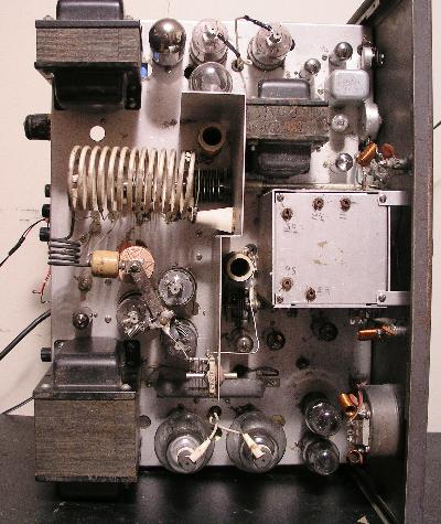
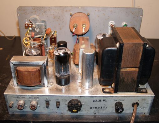
The picture below shows the top of the transmitter chassis.
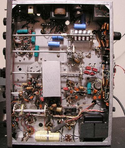
The picture below shows the bottom of the transmitter chassis.
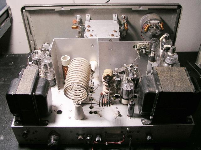
The picture below shows the top of the chassis as viewed from the rear.
Th picture below shows the top of the chassis with the transmitter transmitting into a dummy load. The blue glow are produced by the two # 866 mercury vapor high voltage rectifier tubes.
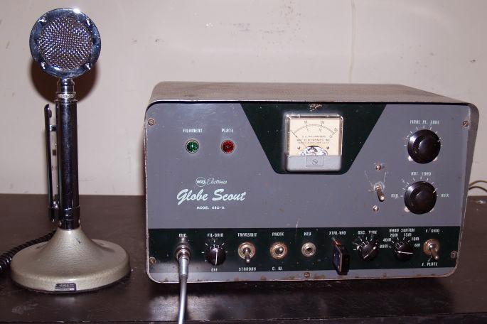
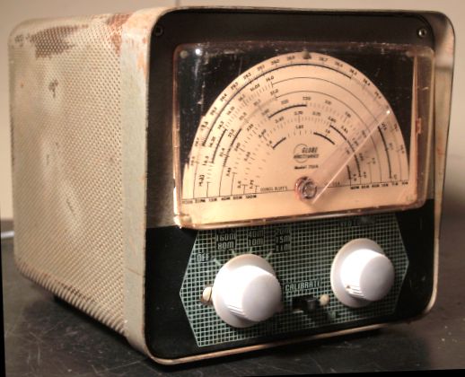
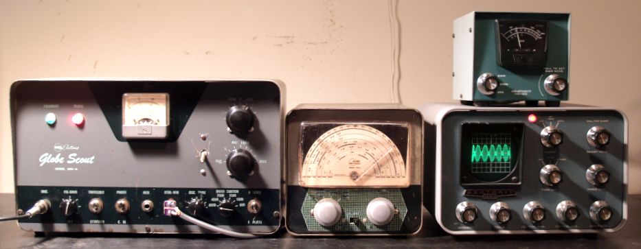
1958 WRL Globe Scout Model 680-A Transmitter
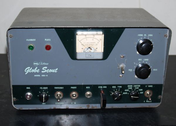
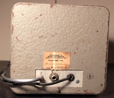
The picture above is a Globe Scout Model 680-A CW and Phone (AM) transmitter that I have. The transmitter was manufactured by World Radio Laboratories (WRL) Electronics of Council Bluff, Iowa. The transmitter was sold as a kit for $99.95 and wired and tested for $119.95.
The transmitter is rated 65 Watts input on CW and 50 Watts input on Phone. It operates on 80 through 10 meters and on 6 meters. It has a pi matching network on 80 through 10 meters and uses link coupling on 6 meters.
The radio has 5 vacuum tubes. A 6V6 tube is employed as a crystal-controlled regenerative oscillator or as an amplifier for an external variable frequency oscillator (VFO). The RF power amplifier employs a 6146 tube operating in Class C. The final amplifier acts as a doubler on 10 and 6 meters.
The speech amplifier employs a 6U8 pentode/triode tube. The modulator tube is a 6L6 tube configured as a modified Heising modulator. The modification is consists of heavily modulating the screen of the 6146 RF output tube as well as the plate. The meter on the front panel measures the grid current and plate current of the 6146 tube. The power supply uses a 5U4 GB tube as a full wave rectifier. The power supplies 500 Vdc at 200 mA.
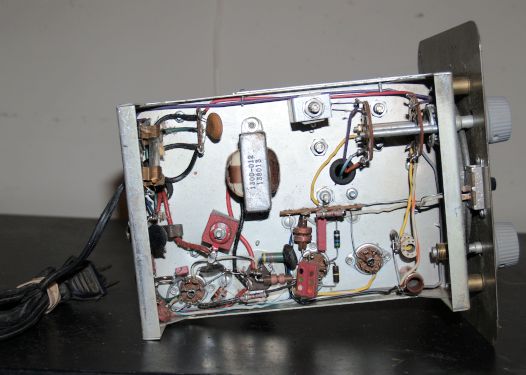
I purchased the transmitter along with the assembly and instruction manual at a hamfest in 2007. The only repairs I made was to replace the power supply filter capacitors and a bias resistor for the final amplifier along with cleaning all the switches. When I brought the transmitter up using a variac, I heard a muffled "pop" suggesting that one of the filter capacitors had either shorted or opened. I quickly turned it off and made the repair. The original capacitors were 12 uF rated at 700 V. A 700V capacitor is almost impossible to find, so I had to series two 22 uF capacitors rated at 450 V with voltage balancing resistors in parallel with each capacitor. One of the final amplifier bias resistors was almost double the value it should be. Although the color bands indicated it was a 22k-ohm resistor, it measured almost 44k ohms. I replaced it with a correct value resistor. After the repairs, the transmitter works well.
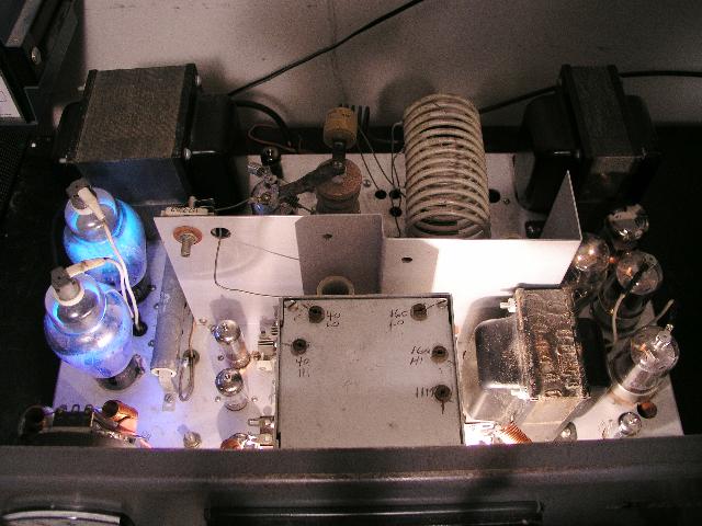
Below is a picture of the underside of the chassis with my capacitor repair.
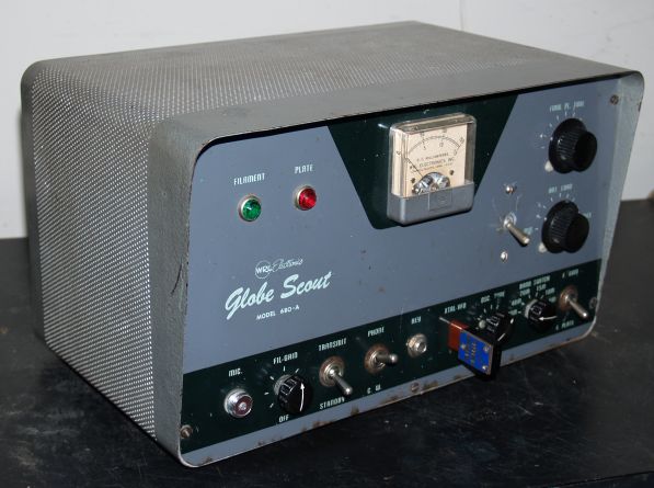
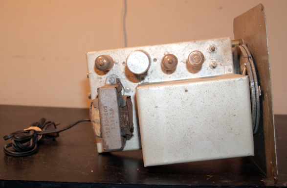
Below is a picture of the top of the chassis after I cleaned it.
Somewhere along the line someone made a modification to the radio by adding a switch to the left of the antenna load control. This switch, when flipped up, shorts the pi network (used for 80 - 10 meters) to ground when operating on 6 meters. Originally this shorting action was performed by turning the plate load control almost fully clockwise. This original method seems marginal to me, and therefore, to improve the reliability of operating on 6 meters and to provide greater plate tuning range, someone added the switch. The cosmetic features of the installation of the switch are not great, but it works and I left it alone.
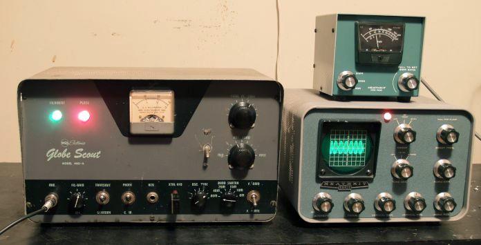
The transmitter works well on both CW and AM. On CW, the transmitter produces nearly 50 Watts output. On AM, the transmitter produces approximately 35 Watts carrier. Below is a picture of the transmitter producing an amplitude modulated output as shown on my Heathkit monitor scope.
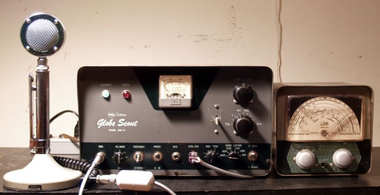
The Globe Scout with an Astatic D-104 microphone makes a neat-looking vintage low-power amateur radio station as shown below.
Tube Complement
| Oscillator | Final Amplifier | Speech Amplifier/Driver | Modulator | Rectifier |
| 6V6 | 6146 | 6U8 | 6L6GB | 5U4GB |
1958 Globe Electronics Model 755A VFO
To make the Globe Scout more versatile and not bound to a single frequency, I purchased a Globe Electronics variable frequency oscillator (VFO). The Model 755A is made to operate with the WRL Globe Scout or Globe Chief transmitters. Below are pictures of my Globe Model 755A VFO after I cleaned it up.
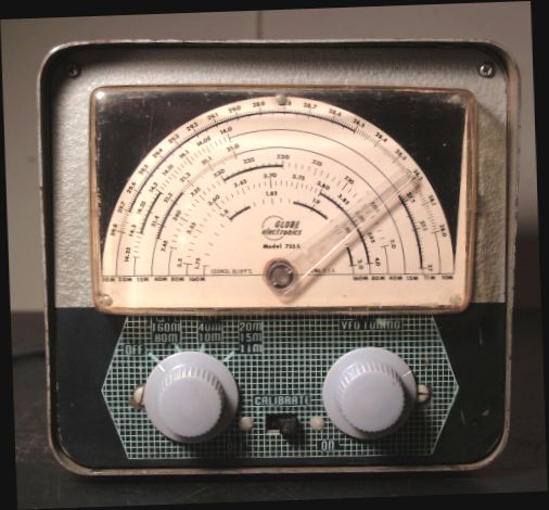
The VFO has fundamental outputs in the 80 and 40 meters ham bands. Output on all other bands up to 10 meters is accomplished by using harmonics.
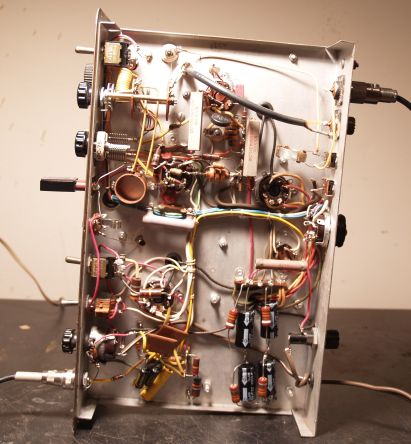
The VFO was extremely dirty when I receive it. There was a thick layer of dust all over the chassis as shown in the picture below.
I cleaned it up and it looks good as shown by the picture below of the underside of the chassis.
The power supply has a selenium rectifier that can be seen in the picture above. It is still functional as is all of the rest of the circuit so I decided to leave everything alone.
The VFO has 3 tubes:
| Oscillator | Buffer Amplifier | Voltage Regulator |
| 6AU6 | 6CB6 | 0A2 |
The VFO with the Globe Scout transmitter make a complete nice-looking vintage station. I had to make a cable to connect the VFO output to the transmitter crystal socket. This setup is shown below:
That setup with a D-104 is compete station ready for operation as shown below:
Late 1950's Gonset Model G-66B Mobile Receiver
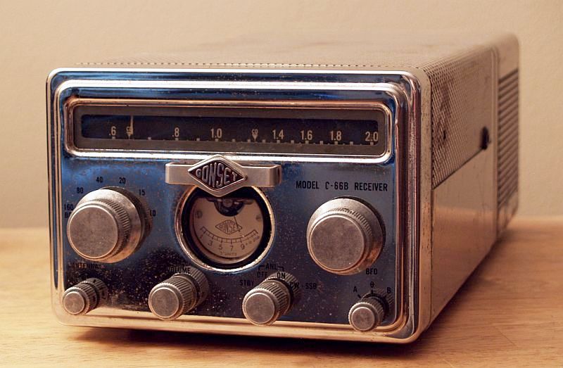
The picture above shows a Gonset Model G-66B Mobile Receiver I have manufactured by Gonset of Burbank, CA. Although the receiver was intended for mobile operation, it can be operated indoors using 115Vac. The radio weighs 8 pounds and the No. 3069 115 Vac/12 VDC power supply weighs 6 1/2 pounds. Dimensions are 16 in. long including the power connector and knobs, 4 1/2 in. high and 6 1/2 in. wide. The receiver uses vacuum tubes and covers 0.54 MHz to 29.7 MHz in six bands. The receiver receives AM and CW/single sideband. The receiver has a variable-frequency Beat Frequency Oscillator (BFO) for CW and single sideband. There is also a antenna trimmer for the antenna, and a switchable Automatic Noise Limiter (ANL). The radio has a dual conversion frequency plan with the first IF at 2,050 kHZ and the second IF at 265 kHz. You can read more about it here
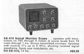
Heathkit SB-610 Monitor Scope
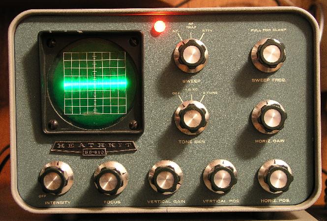
The picture above shows a Heathkit SB-610 monitor Scope I have. This scope is used to display "on-the-air" signals. It displays the transmitted signal envelope. It can measure amplifier linearity using a trapezoid pattern and it can display the radioteletype (RTTY) cross pattern. The scope has a built-in coupler to extract a sample of the transmitter waveform. This coupler is good from 160 meters to 6 meters. The scope also has an intermediate frequency (IF) input that can sample the IF of a receiver to monitor received signals. The scope also has a two-tone audio generator for testing transmitters.
The scope is actually a simple oscilloscope with an uncalibrated 1-tube vertical amplifier and an uncalibrated variable horizontal sweep. You could use it as a simple low-frequency oscilloscope.
The scope has the same cabinet and front panel styling of the Heathkit SB series of amateur single-sideband equipment.
When I bought the scope at a hamfest, the high voltage winding of the power transformer was open. I purchased a used transformer with a 600-V winding and installed it at the back of the chassis. It sticks out the back a bit, but it does not look too bad. I did not use the two filament windings, so I tied them off. Thus the scope now has two power transformers - the original that provides the filaments and 215 Vac, and a second that supplies 600 Vac. The scope works well now with my repair.
The picture above shows an actual signal received off the air through my Drake R-4B receiver that I added a tap (100 pF capacitor) to extract a sample of the 50-kHz IF for display.
Below is an advertisement for the Heathkit SB-610 from the 1967 ARRL Radio Amateur's Handbook. Note the 1967 price is $10 less than the 1970 price shown above.
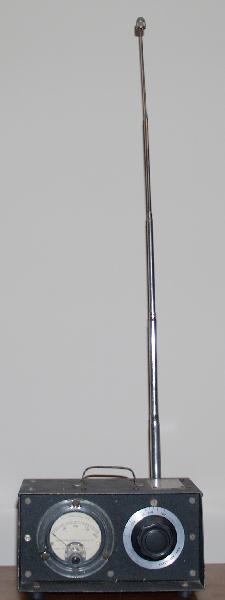
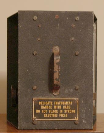
VHF Field Strength Meter
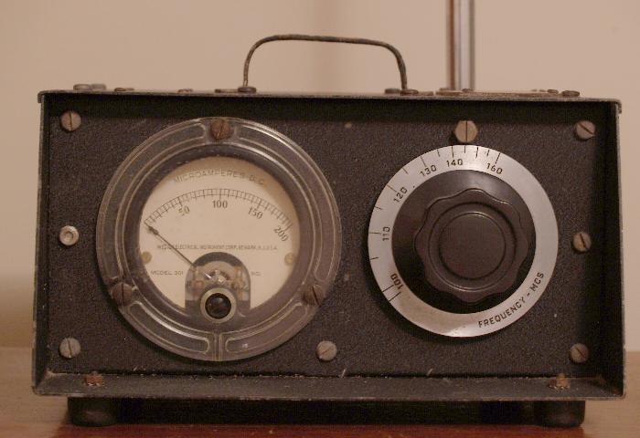
The picture above shows a military surplus VHF field strength meter I acquired at a hamfest. The meter is continuously tuneable from about 95 MHz to 160 MHz. It is a simple passive circuit comprising a tuned circuit, a diode detector, and a sensitive 200 uA meter. There is an extendable whip antenna on the back and a spare diode wrapped in lead on the inside. The meter is quite sensitive as it can detect my 1.5W 2M handitalkie several feet away. I use it to determine if I am transmitting with reasonable power output.
 |
 |
1985 Yaesu FRG 9600
VHF/UHF General Coverage Receiver
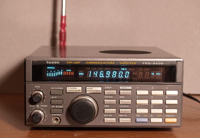
The picture above shows a Yaesu Model FRG 9600 VHF/UHF General Coverage Receiver that I acquired a long time ago. The receiver covers 60 to 905 MHz continuously. It receives wideband FM for broadcast FM and TV; narrrowband FM for two-way public service, military, business, and amateur; wideband and narrowband AM for the VHF aeronautical band; and CW and SSB for amateur and military two-way communications (SSB is only to 460 MHz). I also have the optional video adapter board so I can receive NTSC video from broadcast TV stations. The radio requires 12 Vdc.
Tymeter Digital Clock
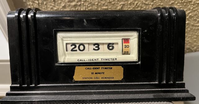
The picture above shows a Tymeter Model 124 digital clock manufactured by Pennwood Numechron Company of Pittsburgh, PA. The time "digits" are on a rotating drum powered by an electric motor. This device was used in amateur stations to remind the operator when to identify the station every ten minutes.