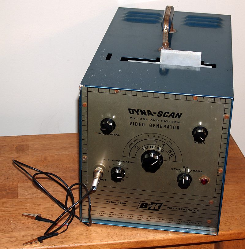
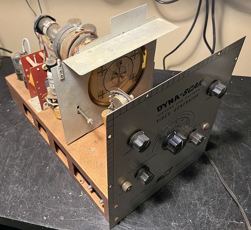
The picture above is of a Video Generator manufactured by B&K Dynascan (circa 1956). This instrument permits a service technician to locate troubles in television receivers by the "signal substitution" technique. It is designed for analyzing black and white VHF tube-type (and solid state) analog television receivers. The instrument is primarily intended for use in the television service shop. Tube testing during a service call in the home would be the first step in television servicing.
The instrument generates a video test pattern similar to the test patterns seen on analog television long ago, typically before the television station signed on the air early in the morning. The video image is generated by a "flying spot" scanner implemented by a cathode ray tube (CRT) operating in the near ultravilot range. The picture below shows the operating principle of the "flying spot" scanner.
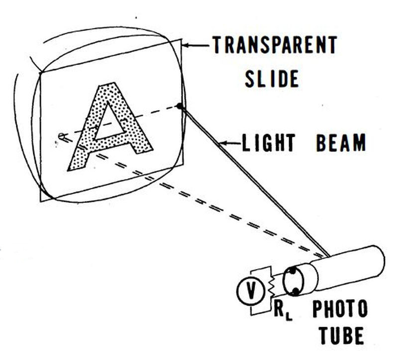
The CRT scans a spot across a transparency containing the pattern. A photomultiplier tube on the other side of the transparency receives the scanning spot and converts the scanning spot to a video signal. The video is combined with vertical and horizontal sync signals to create a television video signal. The picture below shows the transparancy in its carrier pulled out of the instrument.
The controls on the front panel include:
Horizontal Control, that slightly adjusts the horizontal sweep frequency
Video Contol, that adjusts the intensity of the video image
RF Contnuous Tuning Control, that adjusts the carrier frequency (upper channels are apparently produced by harmonics)
RF Attenuator, that adjusts the RF signal level
OFF/ON/BARS Control, that turns the insrument ON and OFF and produces vertical (and horizontal) bars in addition to the image on the tansparancy
The RF connection is made using a round "button"-type connector made by Switchcraft. This connector was often used for microphone connections. The mating connector and cable was missing; I found a connector and made the cable shown in the pictures above.
This instrument is the predecessor to the B&K Model 1077 TV analyst that B&K produced in the 1960's. You can read about that instrument by clicking Here.
The picture below shows the instrument when I received it. I purchased the instrument at an estate sale.
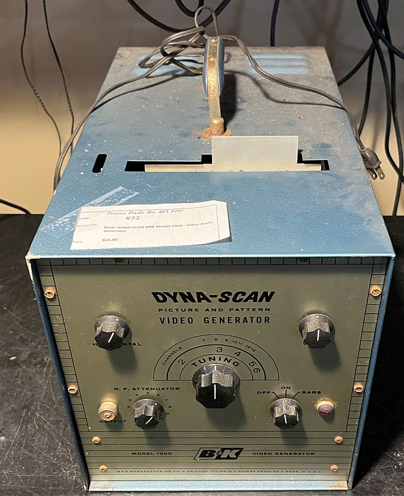
The unit appeared to be in reasonable shape, but a little dirty.
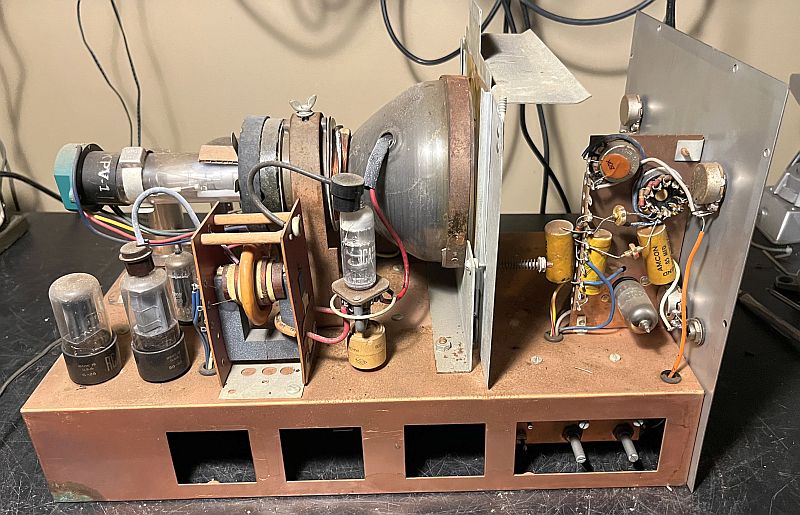
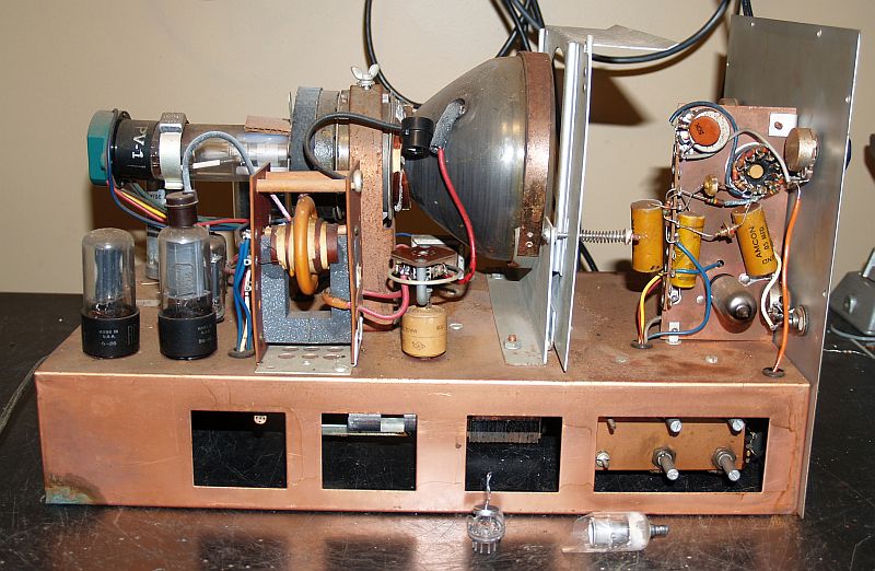
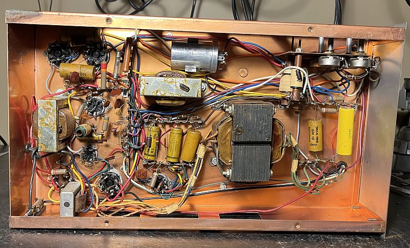
Below are pictures of the chassis after removal from the metal cabinet.
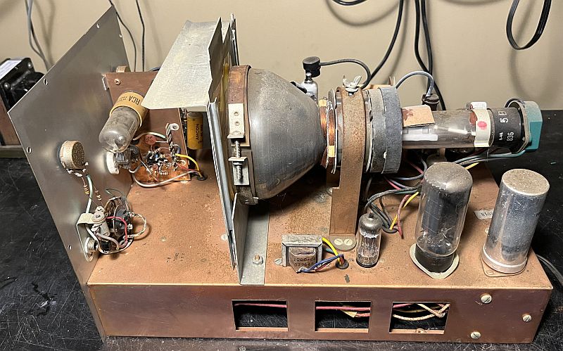
Note the discolored 1X2B high voltage rectifier vacuum tube in the picture above. This indicates the tube is most likely bad.
Note the broken 1X2B high voltage rectifier vacuum tube beside the chassis. When I attempted to remove the tube, the glass envelope broke. I replaced the tube with a good tube.
Below is a picture of the inside of the cabinet when received.
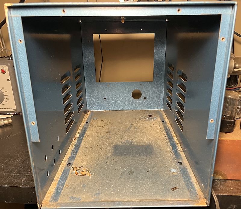
As the above pictures show, there was not a lot of dirt, dust, and grime inside. The instrument cleaned up nicely.
After cleaning the chassis and tubes, especially the photomultiplier tube, I initially powered up the instrument slowly using a variable transformer. All of the vacuum tube lighted, but no image was produced when connected to a television receiver. An RF carrier was produced, but no image. As such, I decided to replace all of the wax paper capacitors.
When testing the unit after the capacitors were replaced, the horizontal frequency measured about 18 kHz. Adjusting the coil in the horizontal circuit brought the frequency down to 15.75 kHz. The newer capacitors have a more precise capacitance value than the old wax paper capacitors and thus requires readjustment of the oscialltor resonant tank circuit.
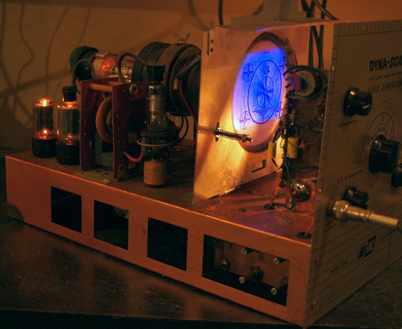
The pictures below shows the CRT illuminating the transparency.You can see the purple color of the CRT.
Below is a picture of the image as presented on a small television connected to the insrument. I had to adjust the instrument's vertical size and linearity to produce a correct image.
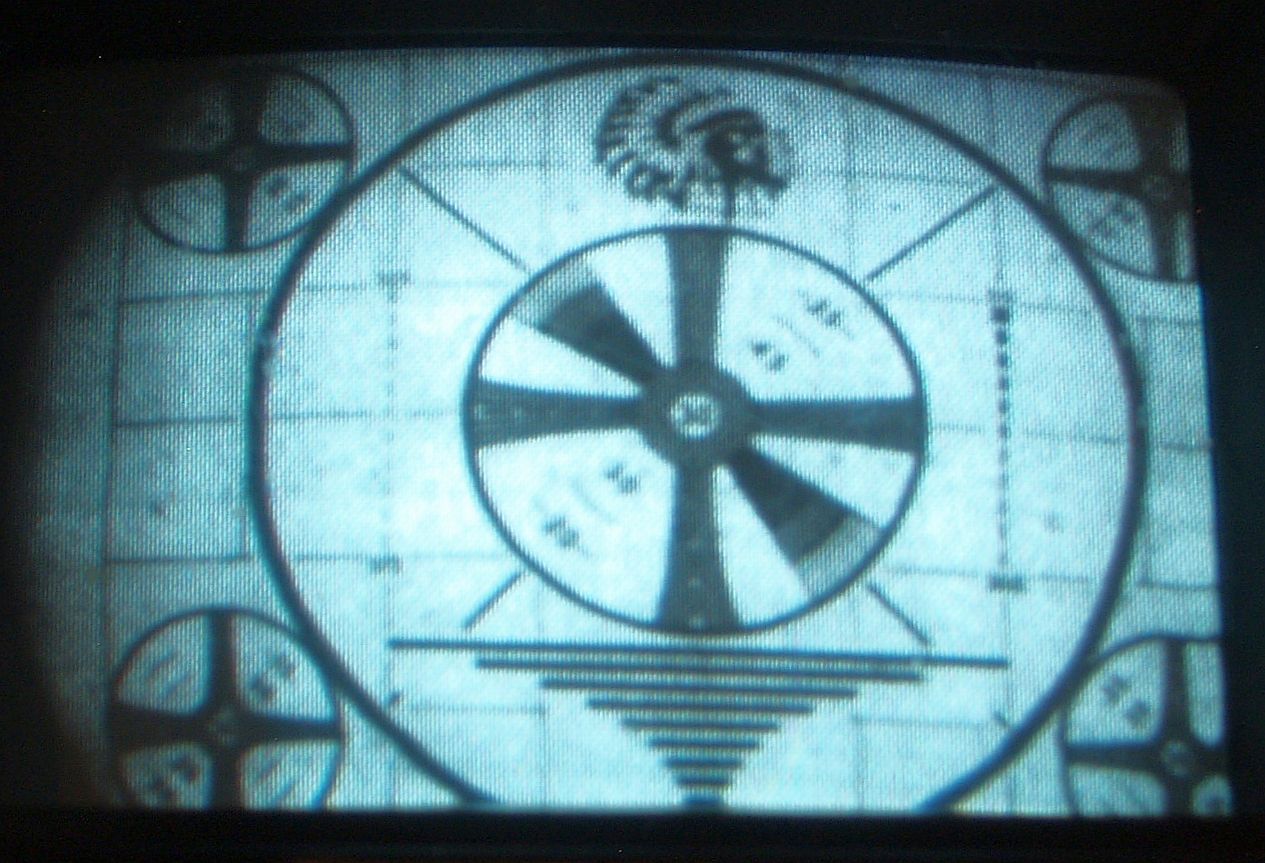
The transparancy that produces the image is shown below.
The image is a copy of the classic Indian-head test pattern created by RCA for checking focus and resolution of television transmissions.
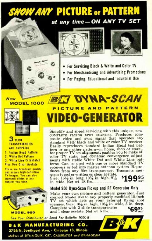
Below is an advertisement for this instrument extracted from the September, 1956, issue of Radio Electronics magazine. The instrument sold for $199.95.