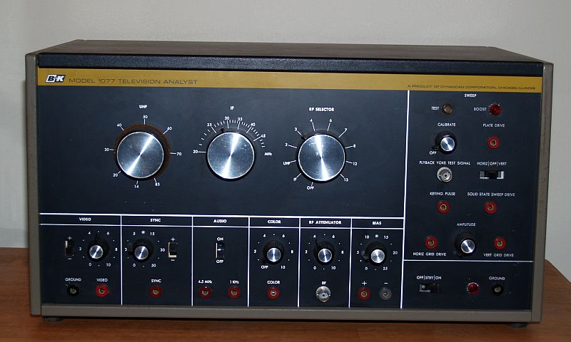
The picture above is of a 1968 B&K Model 1077 Television Analyst. This instrument permits a service technician to quickly and accurately locate troubles in television receivers by the "signal substitution" technique. It is designed for analyzing black and white and color, VHF, and UHF tube-type and solid state analog television receivers.
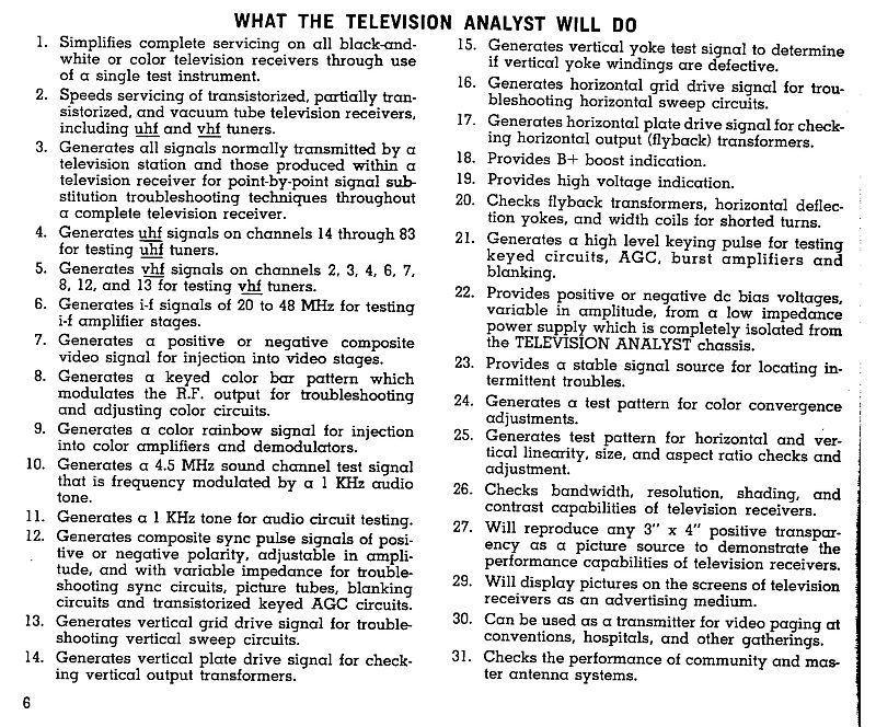
The instrument is primarily intended for use in the television service shop. Tube testing during a service call in the home would be the first step in television servicing. The picture below from the Instruction Manual describes what the Television Analyst will do.
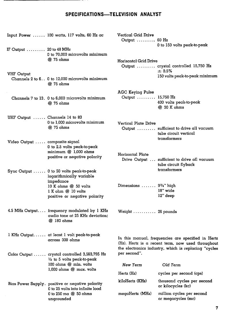
Below are the specifications of the instrument.
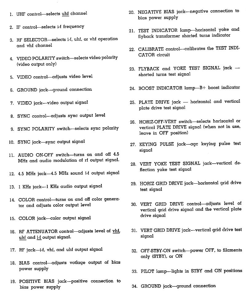
Below is a list of the operator controls on the front panel of the instrument.
The instrument generates a video test pattern similar to the test patterns seen on analog television long ago, typically before the television station signed on the air early in the morning. The video image is generated by a "flying spot" scanner implemented by a cathode ray tube (CRT) operating in the near ultravilot range. The picture below shows the operating principle of the "flying spot" scanner.
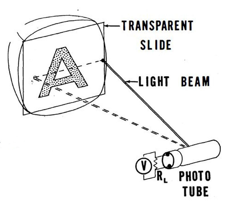
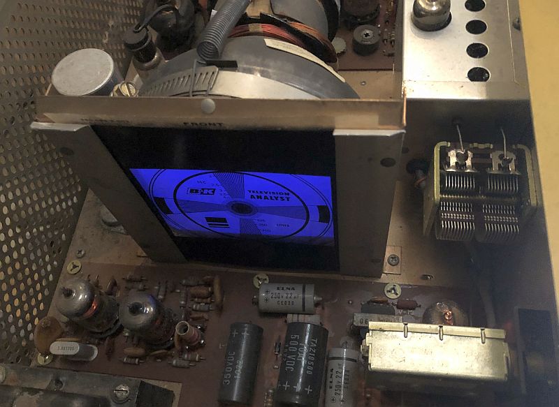
The CRT scans a spot across a transparency containing the pattern. A photomultiplier tube on the other side of the transparency receives the scanning spot and converts the scanning spot to a video signal. The video is combined with vertical and horizontal sync signals to create a television video signal. The picture below shows the CRT illuminating the transparency.You can see the purple color of the CRT.
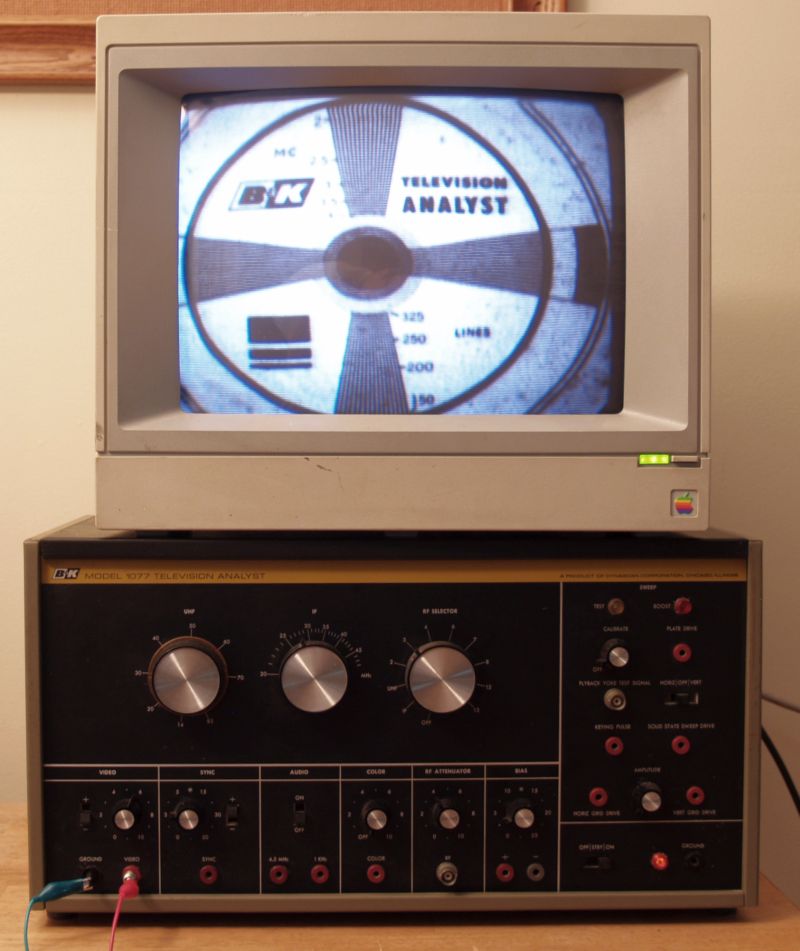
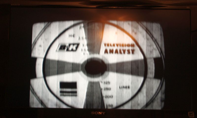
Below is a picture of the Televison Analyst and a video monitor displaying the generated test pattern.
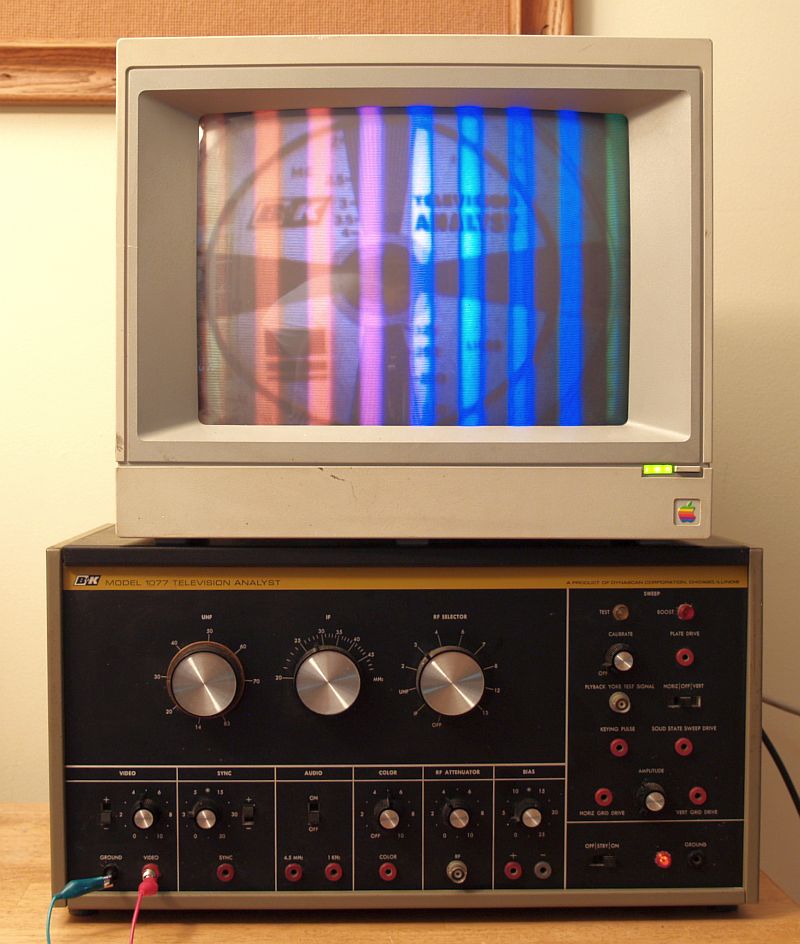
Below is a picture of the Televison Analyst and a video monitor displaying the generated color bars and test pattern.
Below is a picture of the Televison Analyst and an HDTV operating on VHF Channel 3 in the analog mode displaying the generated test pattern.
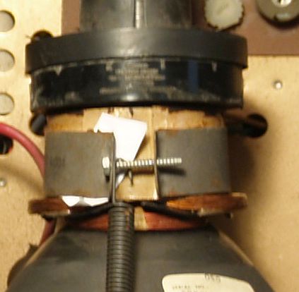
When I received the instrument, it did not work. There was a short circuit in the B+ supply. It turns out, there was no component short; the short circuit was caused by the metal bracket surrounding the yoke on the CRT had, during shipment, pushed against a winding on the yoke and rubbed the enamel insulation off the wiring and shorted the yoke winding to ground. The large stiff spring that pulls the bracket forward further enhanced this situation.
I repaired it by inserting a piece of paper between the yoke and bracket. You can see the paper in the picture below.
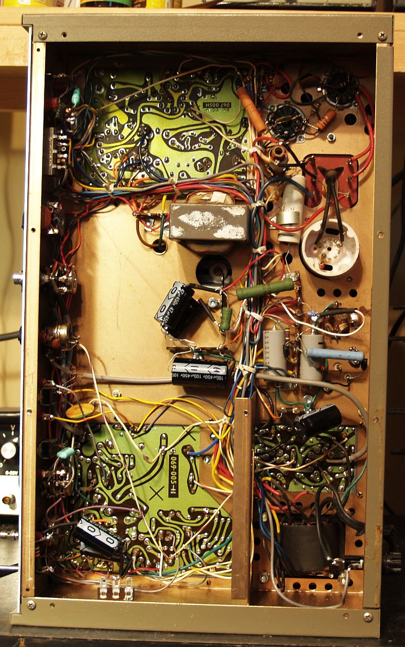
I did change out all of the electrolytic capacitors in this instrument. Below is a picture of the bottom of the instrument after re-capping.
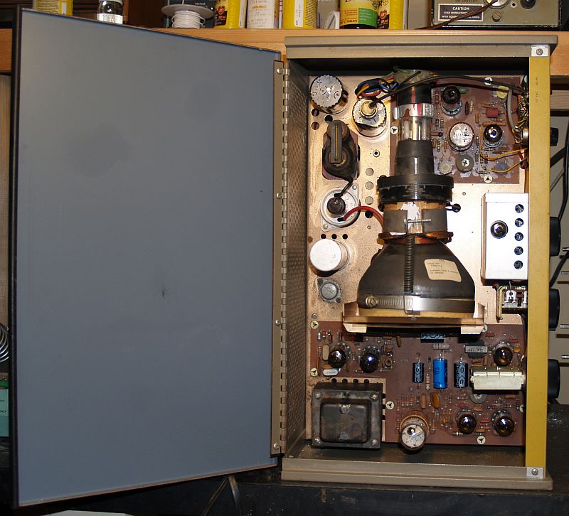
Below is a picture of the top of the instrument after recapping.
When I finally got the instrument to function, there was jitter in the horizontal sync signal. This jitter caused the video test pattern image to look like the picture below.
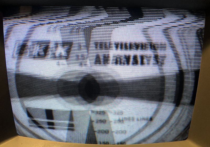
It turns out that the frequency of the horizontal must be adjusted (by a potentiometer on a circuit board) fairly accurately because the color burst is injected into the oscillator.
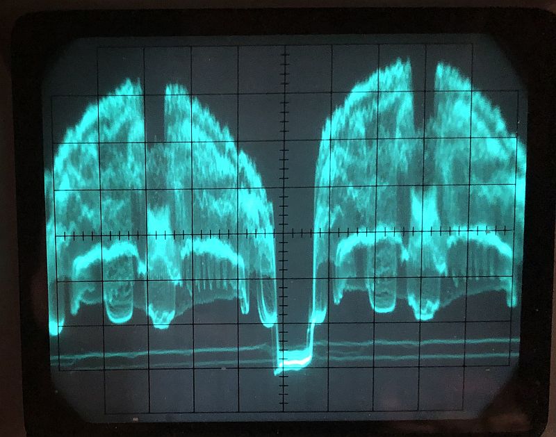
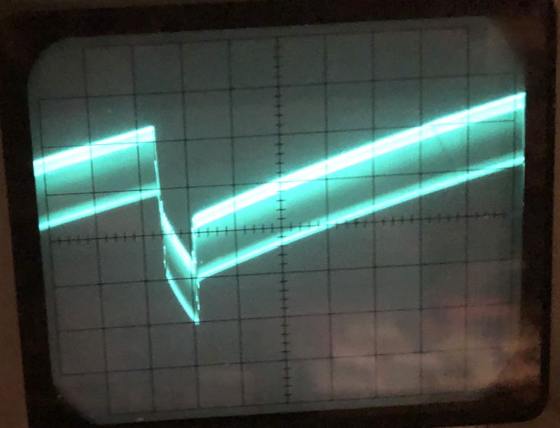
A proper video out signal on the front panel is shown on the oscilloscpe display below.
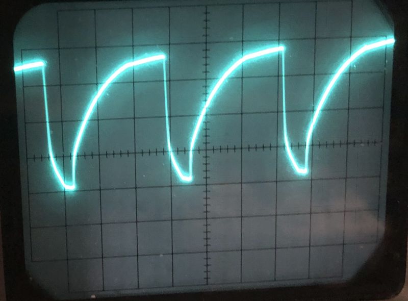
A proper horizontal signal on the front panel is shown on the oscilloscpe display below.
A proper signal to the plate of the sync mixer is shown below.
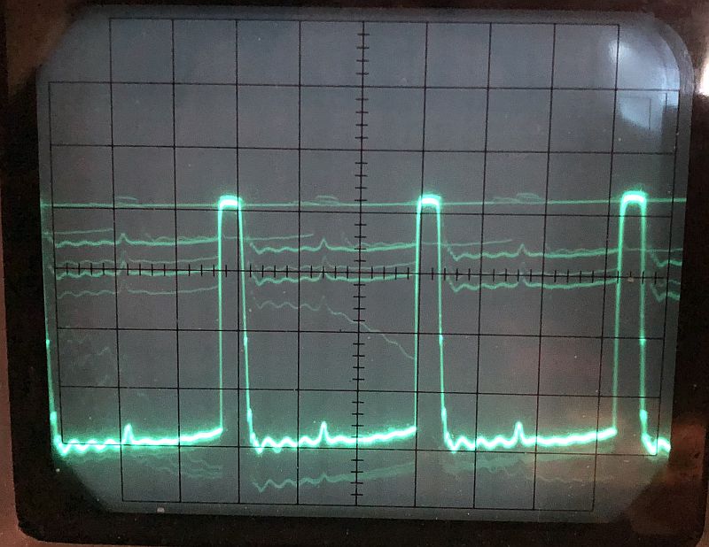
A proper vertical drive signal is shown below.
Another problem I had with the instrument concerned the RF output. At first, the instrument did not produce any output at IF or RF. I sprayed D-Oxit on the rotary wafer switch in the tuner unit and IF and some RF was produced, but only with the RF gain control near maximum. The IF would disappear at the low and high ends of its range. The IF and RF would disappar if the RF gain control was adjusted downward from maximum.
And no RF on Channel 2 was produced. I replaced the 6CB6 tube in the tuner with a new one and the instrument now produces all of the RFs and IF and across the RF gain control range. The 6CB6 tube tested good on my tube tester, but the tester does not test at VHF.
The filaments of all of the vacuum tubes in the instrument are in series.
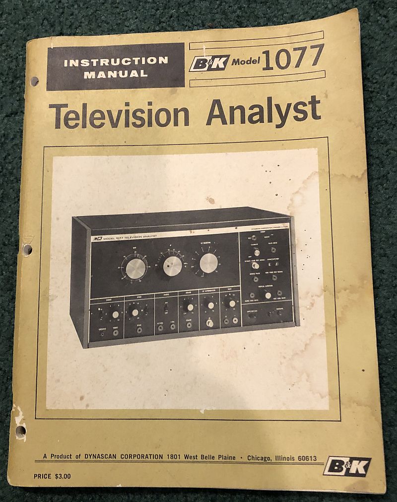
Below is a picture of the Instruction Manual.
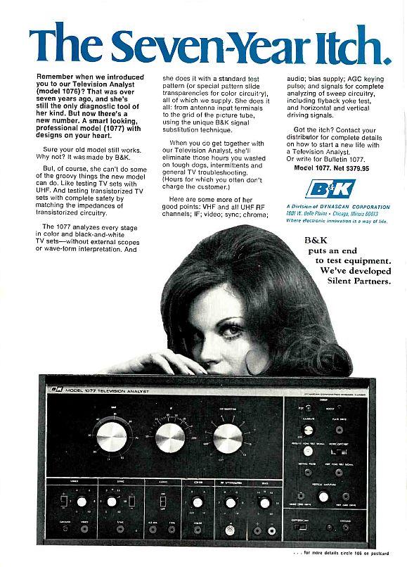
Below is a advertisement for the instrument in the May 1969 issue of the Electronic Technician/Dealer monthly magazine. The instrument sold for $379.95 at that time.
This instrument is the succesor to the B&K Model 1076 TV Analyst, produced circa 1961, and the Model 1000 Video Generator that B&K produced circa 1956. You can read about the Model 1000 Video Generator by clicking Here.