


Band No. |
Center Wavelength (um) |
||
(with reflected daytime component) |
|||
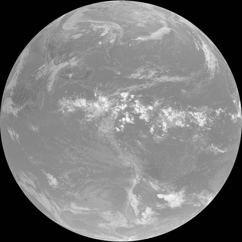
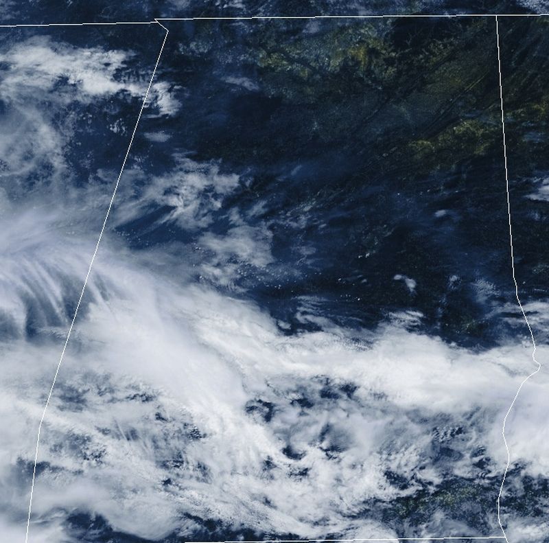
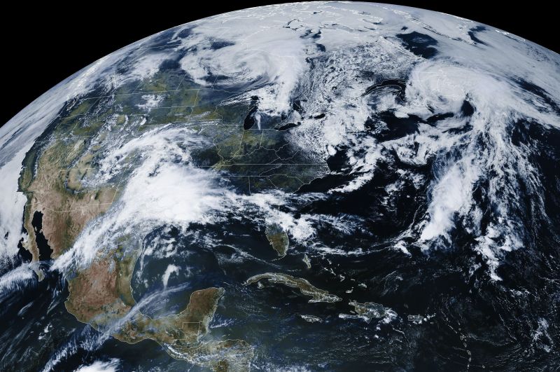
GOES-16/17 (ABI) Full Disk Spatial Res: 2 Km |
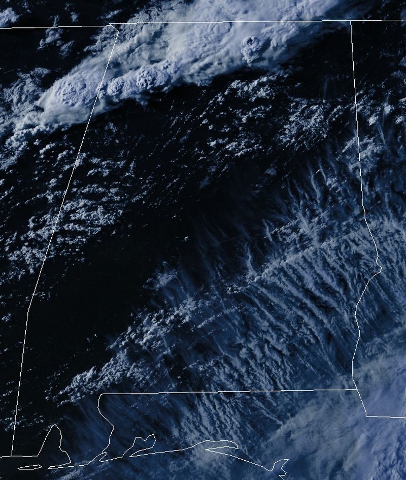
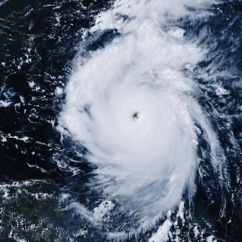
Band 2 Visible |
HRIT/EMWIN System from ABI |
Full Disk Every 30 Minutes |
GOES-16/17 (ABI) Full Disk Spatial Res: 2 Km |
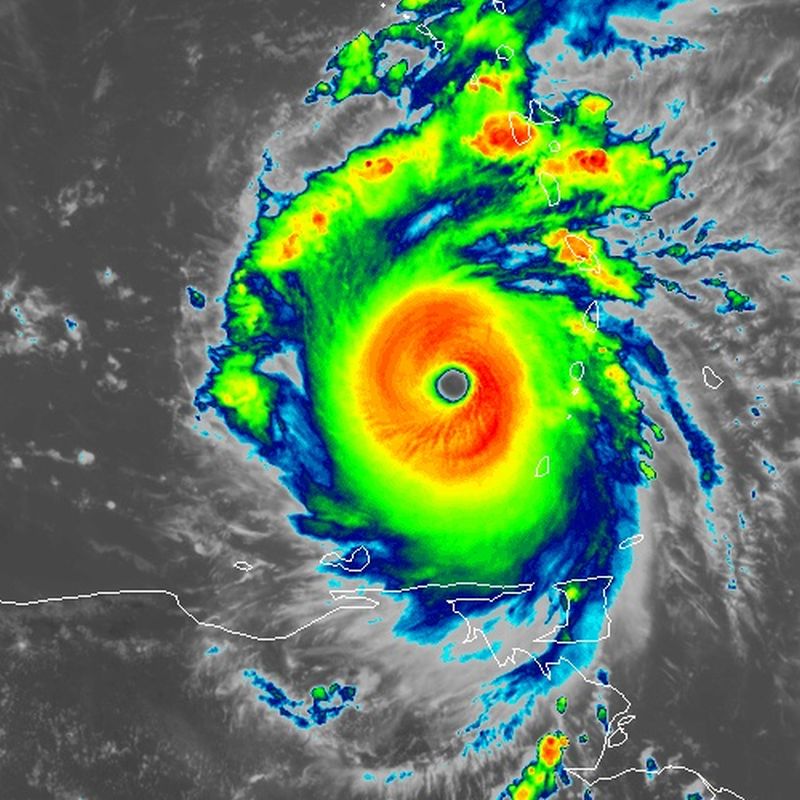
Band 7 Infrared (SW IR) Band 8 Infrared (IR/WV) Band 9 Infrared (IR/WV) |
HRIT/EMWIN System from ABI |
Full Disk Every 30 Minutes |
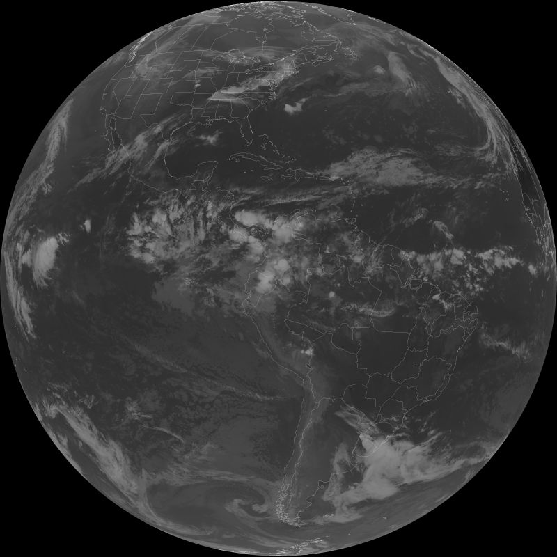
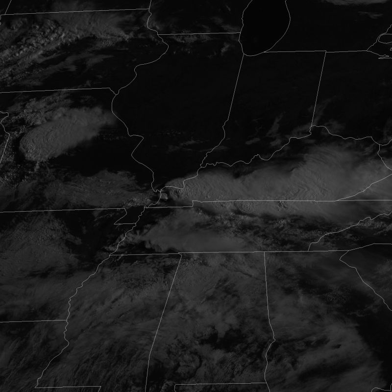
GOES-16/17 (ABI) Full Disk Spatial Res: 2 Km |
Band 13 Infrared (LW IR) Band 14 Infrared (LW IR) Band 15 Infrared (LW IR) |
HRIT/EMWIN System from ABI |
Full Disk Every 30 Minutes |
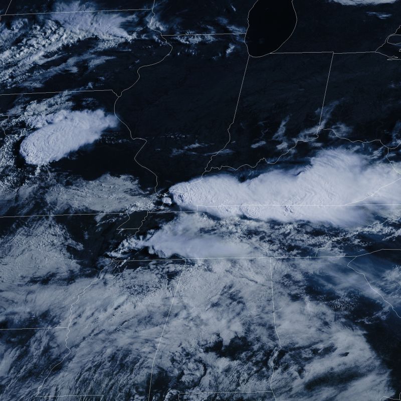
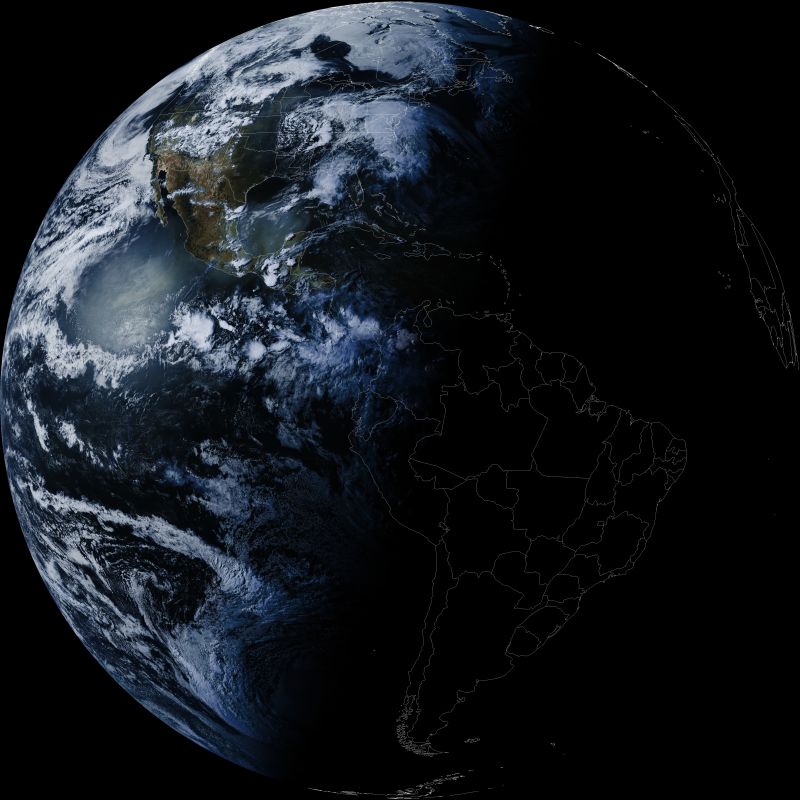
GOES-16/17 (ABI) Full Disk Spatial Res: 2 Km |
Band 2 Visible Band 7 Infrared (IR/VW) Band 13 Infrared (IR) |
HRIT/EMWIN System from ABI |
Full Disk Every 15 Minutes |
Products |
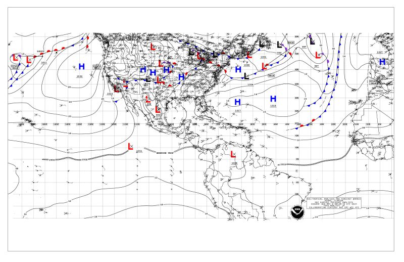
National Hurricane Center |
||
Weather Information Network (EMWIN) |
EMWIN Program |
||
Collection System (DCS) |
Program |
||
(N/A - Manually entered in response to events) |
As Needed |
||
1. Visible 2. Infrared 3. Water Vapor |
Meteorological Agency and NOAA/NESDIS/OSPO |