GOES Weather Facsimile (WEFAX) Receiver
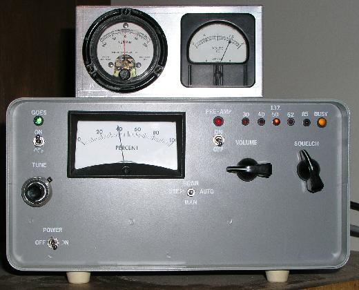
This is a receiver I made to receive the weather facsimile (WEFAX) pictures
transmitted by the GOES satellite on 1691 MHz. The picture above is the indoor
portion of the receiver setup. The downconverter is outside next to the antenna.
The indoor portion is an FM receiver that receives a signal near 137 MHz. The
receiver is built around the WEFAX receiver sold by Hamtronics. I purchased only
the circuit board and electronic parts (less cabinent), assembled the parts, and
installed it in a cabinet made by LMB. I also substantially modified the Hamtronics
receiver to add a signal strength meter (shown in the picture as "percent"),
the yellow "busy" LED to indicate that a signal has broken the squelch threshold, and
other circuitry to improve sensitivity and to accommodate the downconverter.
There are presently 2 GOES satellites serving the United States. GOES 12 is the
Eastern satellite and GOES 10 is the western satellite. Because I live in the
east central US, I have aimed my antenna to receive GOES 12.
GOES WEFAX picture information is transmitted on 1691 MHz. Picture information
is conveyed on a 2400 Hz subcarrier that is frequency modulated on the 1691 MHz carrier.
The amplitude of the 2400 Hz subcarrier conveys brightness of the picture. A
large amplitude is a bright picture. I added a 2400 Hz bandpass filter to the
detected output of theHamtronics receiver to increase the overall receiver sensitivity.
I also added an automatic frequency control (AFC) circuit to the reciever frequency
discriminator to control the frequency of the variable frequency oscillator (VFO) located in
the outdoor downconverter.
On the left of the reciever shown above there is a green LED that indicates that
the GOES downconverter is on. Below the LED is a switch to turn the downconverter
on and off. The "tune" control below the switch manually controls
the VFO to tune the receiver to 1691 MHz. Once the AFC locks on, no further tuning
is recquired.
The two meters on top of the receiver indicate tuning status. The meter on the left
is a center-tune meter connected to the receiver frequency discriminator and indicates
if the signal is tuned to the center of the receiver passband. The meter on the rignt
indicates the VFO tuning voltage and helps in tuning the receiver to 1691 MHz.
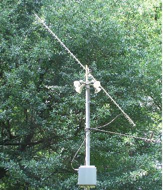
The picture below shows the downconverter and antenna mounted to a pole in my back yard.
This installation is about 150 feet away from the house and is the only place
in my back yard where I can get an clear view of the sky. Tree foliage will significantly
attenuate the signal from the satellite. The downconverter (the square box) is
attached to the pole with u-bolts.
The downconverter is contained inside a steel weatherproof box. Connections to
the box include dc power and downconverted output on the bottom, and RF antenna
input on the left side. The picture below shows the inside of the downconverter
with its cover (door) open.
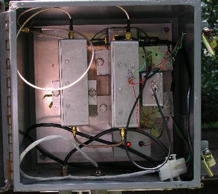
The rectangular metal box on the left is the microwave RF preamplifier. It uses
a GaAS FET transistor in a microstrip circuit I designed. Its noise figure is
about 1 dB and it has a gain of about 15 dB. To the right of the preamplifier is
the mixer enclosed in a similar sized metal box. The mixer uses a Minicircuits
mixer in a microstrip circuit I designed. The downconvertered output of the mixer
is amplified by a Motorola MWA IC amplifier. The output of the MWA drives 150 feet
of coax that runs to the receiver in the house. The smaller box to the right of
the mixer is the local oscillator which is a Minicircuits variable frequency oscillator
(VFO). The frequency control voltage for the VFO is derived from the AFC circuit
I built into the receiver and is sent to the VFO on the center conductor
of the coax that carries the downconverted signal.The box near the bottom with
the red illuminated LED is a voltage regulator that provides +15Vdc from the +20Vdc
sent to the downconverter from the receiver. Other voltage regulators in the
preamplifier, mixer, and local oscillator provide other voltages as required.
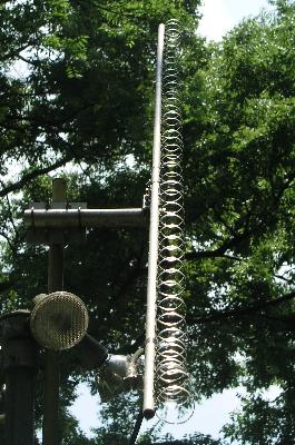
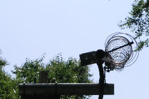
The antenna is a loop Yagi made by Down East Microwave specifically designed
to recieve the 1691 MHz WEFAX signal. Pictures of it are shown
below. One view is a side view and the other is looking down its boom.
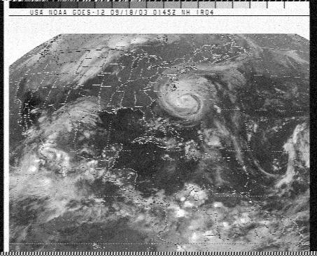
The audio output of the receiver (audio is the bandpass filtered 2400 Hz subcarrier) is
input to the sound card of my computer. I use the WXSat Version 2.3 software program written by
Christian H. Bock to extract the picture information from the 2400 Hz subcarrier. Below
is a GOES WEFAX image I received with this receiver. This image is of Hurricane Isabel
received on 18 September 2003. This image was made with one of the infrared (IR)
instruments on board the GOES 12 satellite. White areas indicate cold temperatures and
black areas indicate warmer areas. Thus clouds are white - the more white they are, the
colder and higher in altitude they are. I have a good signal-to-noise ratio (S/N) with
my reciever and the images that I receive have very little noise as evident
in the picture below. A small amount of noise can be seen in the white areas
outside the earth disk.
Many types of images are transmitted on GOES WEFAX. Another image that is often
transmitted is a closeup of most of the US. A sample of this image is shown below.
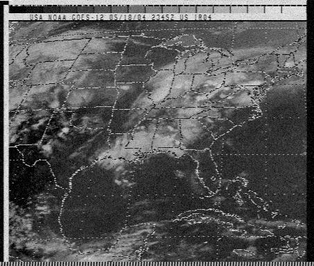
It takes about 4 minutes to receive a complete GOES image. The data conveyed
in a GOES image is about 45 minutes old from when the higher resolution raw digital
data (called GVAR data) is recieved by NOAA. NOAA receives the GVAR data, adds
the geographical and political boundary lines and retransmits it up to the
GOES satellite for retransmission on 1691 MHz as WEFAX.
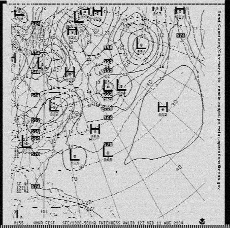
Other types of images that are transmitted include weather charts, images
taken by the US polar orbiter weather satellites such as NOAA 14, and images
of Europe and the Middle East taken by the european weather satellite, METOSAT.
Below is a weather chart I received.
LRIT/HRIT/EMWIN
In the fall of 2004, GOES WEFAX analog transmission was replaced with a new
digital service called Low Rate Information Transmission (LRIT) and subsequently with High Rate Information Transmission (HRIT).
These new services provide higher resolution images compared to the analog GOES WEFAX. Receipt of these new services require a new receiver.
The (digital) LRIT mission replaced the (analog) WEFAX mission. LRIT (operating an operating on 1691.0 MHz)was intended for use on low rate communication links ,
mainly at 10 kbit/s until 256 kbit/s. HRIT (operating on 1694.1 MHz) is intended for use on high rate communication links, mainly at 0.256 Mbit/s through 10 Mbit/s.
The NOAA/NESDIS High Rate Information Transmission/Emergency Managers Weather Information Network (HRIT/EMWIN) broadcast is resident on NOAA's GOES-R Series of Satellites.
Currently, there are no active LRIT broadcasts as the follow-on GOES-R series HRIT/EMWIN broadcasts are active for both GOES East and West. The LRIT broadcast
capability will be a backup service available from the GOES 13, 14 and 15 satellites in the event of a contingency until those satellites are officially de-commissioned.
I built a GOES High Rate Information Transmission (HRIT) receiver to receive
the GOES-R Series relay of reduced resolution imagery. You can read about my GOES HRIT receiver
HERE