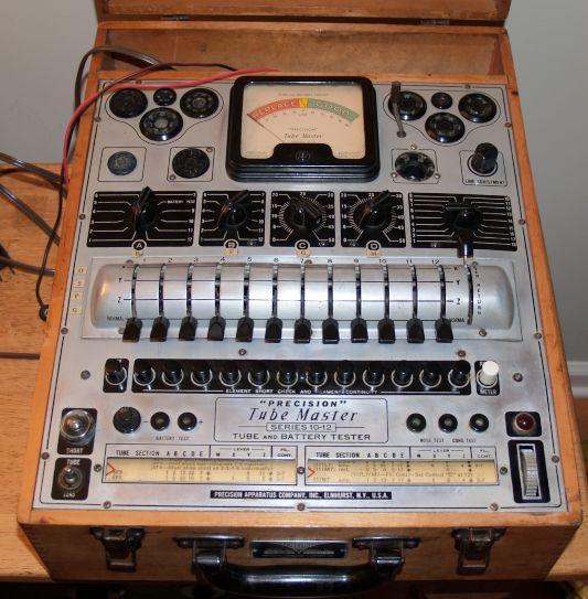
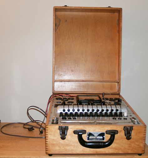
The picture above is a Precision Apparatus Model 10-12 Electronamic Tube Tester I have. I purchased this instrument at a hamfest. After purchasing this instrument, I discovered that it was designed with flexibility in mind such that it would not quickly become obsolete as new tubes are designed and placed in the market. To accomplish this goal, each pin of the 12 maximuum pins can be connected as a control grid, plate, or screen grid via 12 lever switches. This versatility is one reason this tester is popular today. This tester can test tubes manufactured up to the late 1960s, including the tubes in my RL Drake B-line amateur radio station.
The manufacturer of this tube tester touts their unique "electronamic" design tests more than just mutual conductance of a tube. The tester is designed such that individual grid, plate, and screen voltages and loads can be applied to the individual tube elements such that the tube can be tested in a realistic operating condition. The tube merit meter is placed in the plate or output circuit of the tube.
The tester does not test the tube at only one point on its transfer curve. Through application of "appropriately phased individual element potentials", the tube under test is swept through a wide portion of its plate transfer curves. Thus the tube is tested over its operational range and not just at an arbitrary point.
The tester is operated as described below.
1) Ensure all 12 levers are in their "Normal" position.
2) Set control A, B, C, D, and E to the positons indicated on the tube roll chart.
3) Press "Read Meter" pusbutton and remove finger from button. This turns the tester on.
4) Adjust line voltage potentiometer to center the meter needle in the center of the scale.
5) Insert tube a let it heat to operating temperature.
6) Place red or black cap on the grid cap, if appropriate.
7) Press number pushbuttons 1-12 (or 1 up to the maximum number of tube pins) sequentially and
observe the neon light for shorts. Shorts are indicated by a steady glow of the neon light.
The pins correspondig the the filaments will show a steady neon lamp glow. These pins are
indicatd on the tube roll chart.
8) Position the 12 levers to W (open), X (screen grid), Y (plate), or Z (control grid) as indicated in the roll tube chart.
9) Press the "Read Meter" pushbutton and note the reading on the meter.
- Filament voltages from 0.75 to 117 V. including 0.75, 10, 18.9, 35, 45, 70, 85, and 117 V.
- Tests Noval button 9-pin tubes, subminiature types, double cap UHF types, LOCTALS,
Bantam Juniors, single ended, regualr octals, spray-shield and glass types, miniature 7-pin,
and acorn tubes.
- Qualitative tube merit readings directly indicated on a single three-coloreddial supplimented by
a linear scale for tube matching and qualitative comparison purposes.
- Qualitative direct reading dry battery tests tha tests batteries from 1.5 to 135 V under specific predetermined
loads.
- Dual free-point filament terminal selection that locates terminals of all filaments
(single, double, center-tapped) regardless of rotating pin positoin common to many
FM and TV tubes.
- Visible filament continuity checks using the 12 pushbuttons.
- Master element lever operated selector system that completely eliminates all
possibilities of inflexibility.
- Specific individual loads and voltages for control grid, screen, and plate.
- Meter reads only in the plate circuit that results in its indication being entirely dependent
on control action and condition of all tube elements.
- All open tube elements are identified becasue all elements must be intact for a proper meter reading.
- Tests diodes, triodes, rectifiers, tetrodes, pentodes, multi-purpose tubes, gaseous types,
and remote control gaseous tubes regardless of varying filaments or other element positions.
- Noise test jack provided for earphone or amplifier connection.
- Ballast tube tests can be accommodated for open and loose elements and leakage between
sections of multi-section tubes.
- Pilot lamps such as miniature screw based and bayonet types can be tested.
- Micro line voltage adjustment.
- Paper capacitor leakage tests.
I also tested a couple of batteries and good batteries tested good and bad batteries tested bad on the tester.
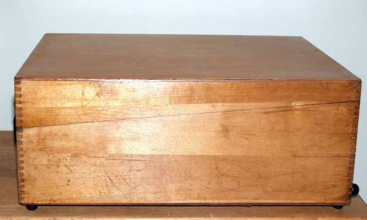
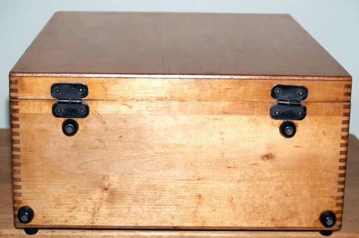
Below are pictures of the chassis before I replaced the line cord. Note the wood case is discolored but in reasonably good shape.


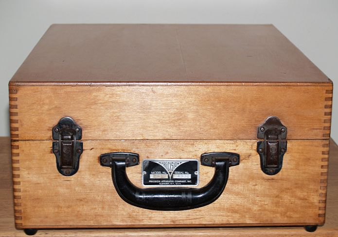
Below are pictures of the tester after I stripped the original finish from the wood case and after I refinished the case with tung oil.
I have two volt/ohm meters made by Precision Apparatus. They can be seen by clicking HERE