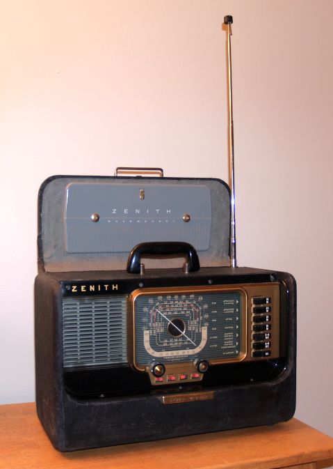
1953 Zenith Model H500 Transoceanic
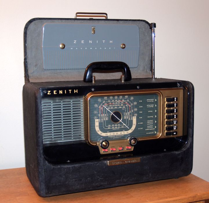
Standard Broadcast from 540 kc to 1600 kc (555M to 188 M)
Weather Band from 4 Mc to 8 Mc (75 M to 38 M)
Weather Band from 2 Mc to 4 Mc (150M to 75M)
Short Wave from 17.5 Mc to 18.1 Mc (16M)
Short wave from 14.9 Mc to 15.5 Mc (19M)
Short Wave from 11.6 Mc to 12.0 Mc (25M)
Short Wave from 9.4 Mc to 9.8 Mc (31M)
Mine has a manufacture date of February 26, 1953 stamped in white inside the case. Thus it was apparently manufactured near the end of the manufacturing period. The model H500 was the last of the trans-oceanics manufactured with only 5 tubes. Subsequent trans-oceanics were manufactured with 6 tubes.
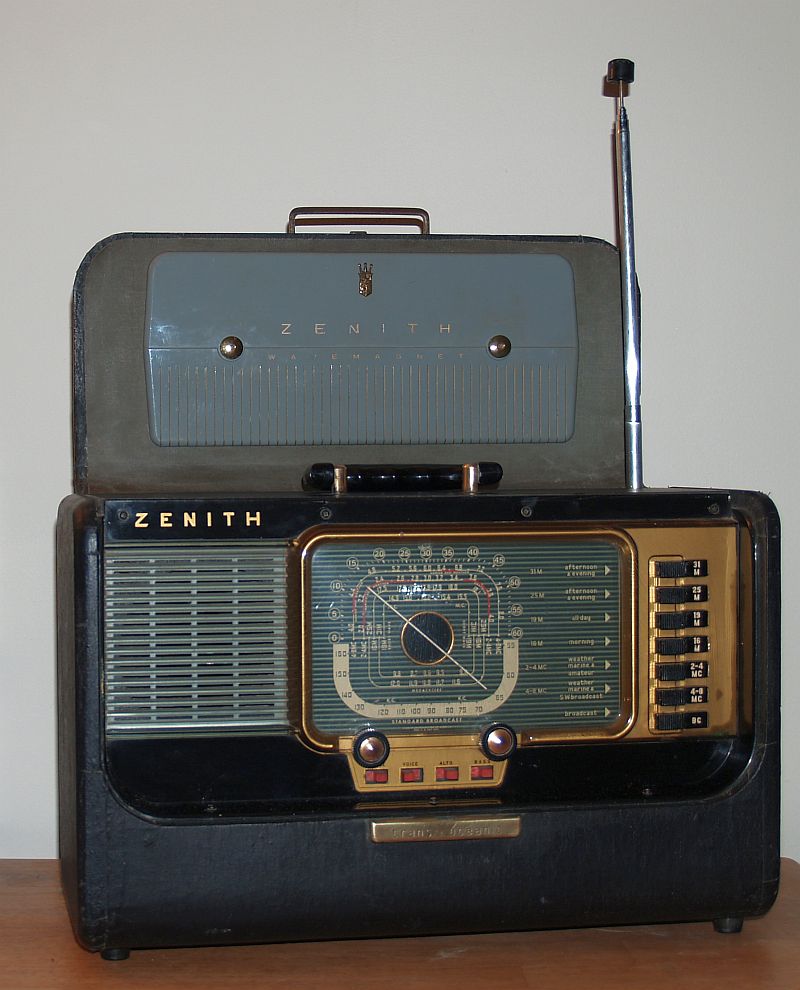
This radio worked when I received it, but the cosmetics were not the best. Pictures of the radio as I received it is shown below.
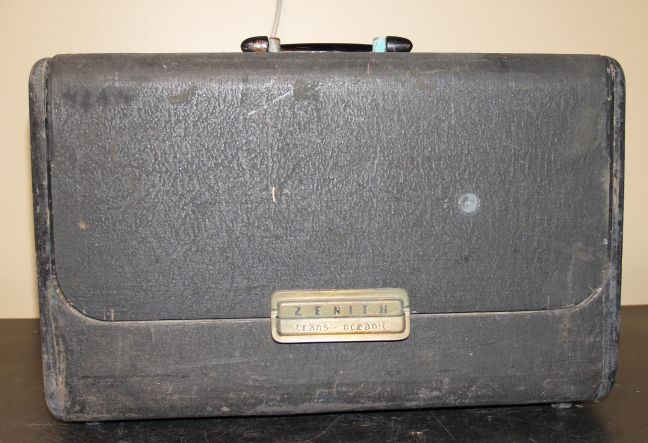
The most noticable cosmetic issues were that it was dusty and the gray backing in the lid behind the Wavemagnet antenna was curled up. I glued the curled up backing back in place using white glue. The cloth covering over the wooden case was mostly in tact, so I did not have to repair it. I rubbed some black shoe polish over some of the bad places on the cloth covering to make the black color more uniform. Another cosmetic issue was the brass latch and the two brass pieces attaching the handle to the case were corroded. Some Brasso and fine steel wool cleaned these brass pieces nicely.
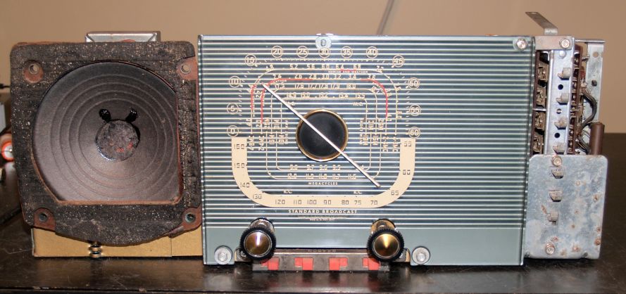
The picture below shows the front of the chassis after removal from the case.
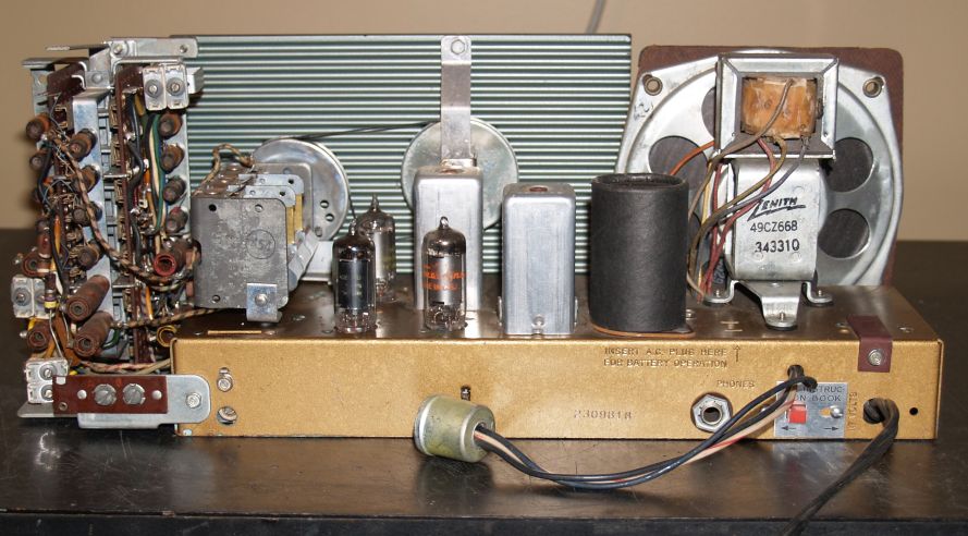
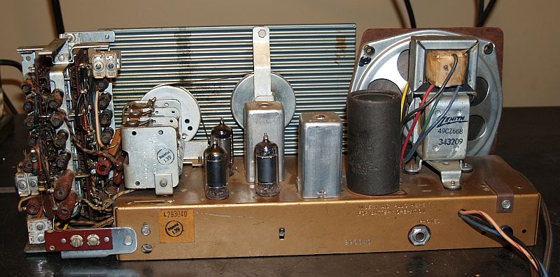
Below is a picture rear of the chassis after I cleaned off the dust.
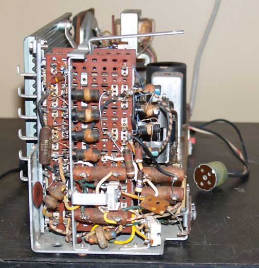
The picture below shows the side of the chassis with the tuned circuits.
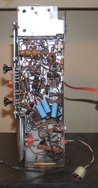
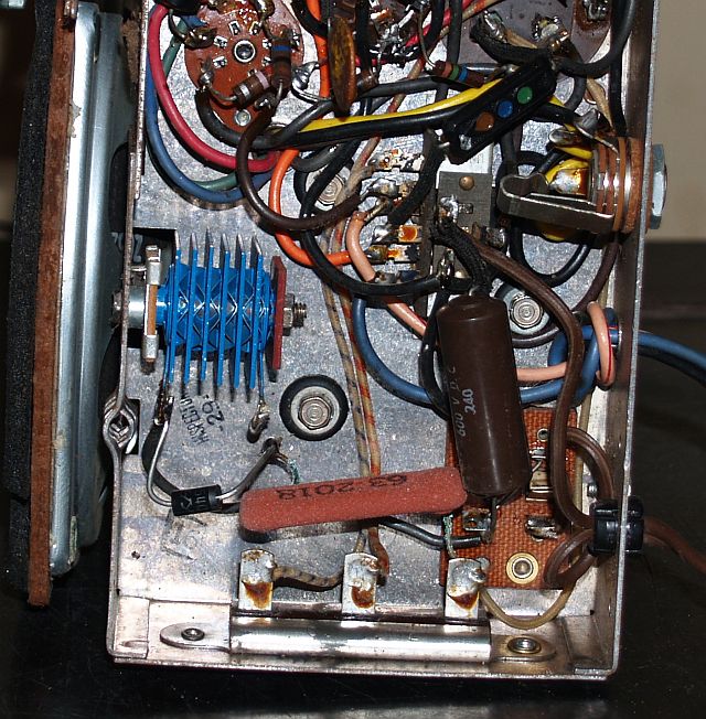
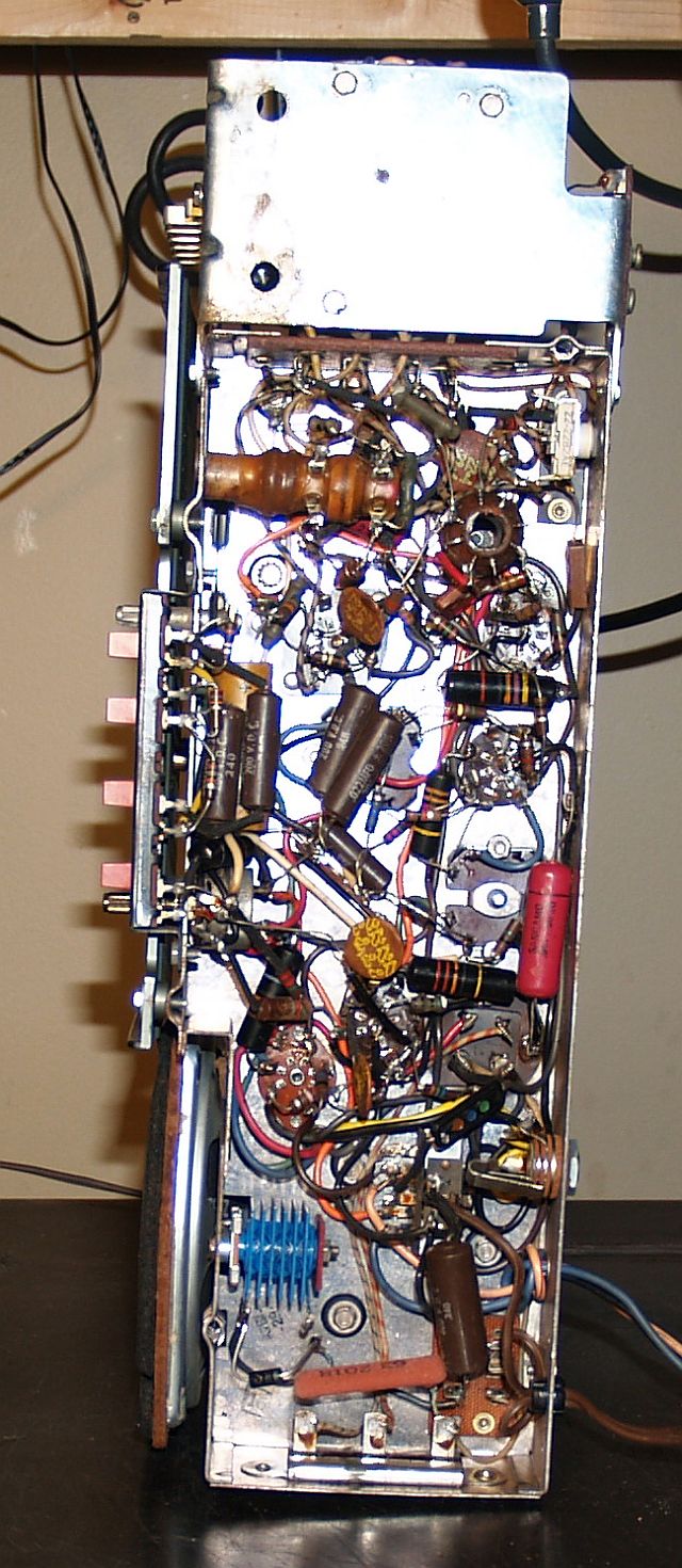
The picture below shows the underside of the chassis. You can see the three blue electrolytic capacitors I added to the power supply filter circuit to reduce the hum.
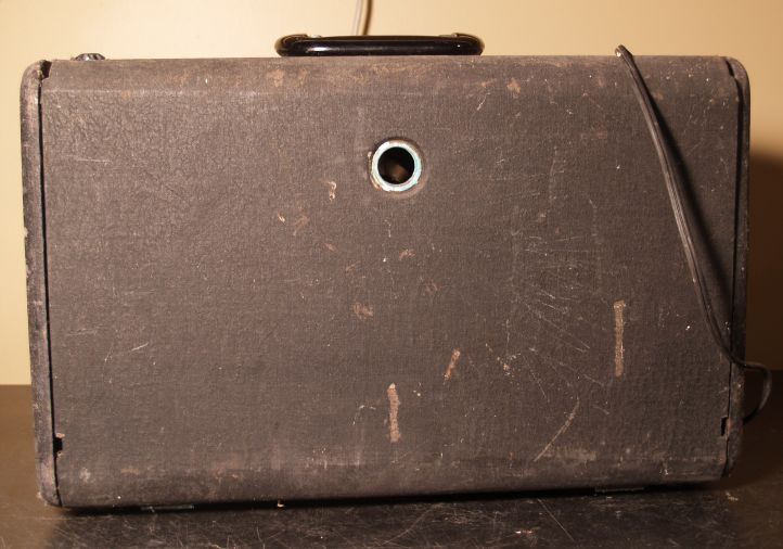
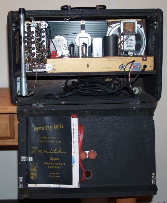
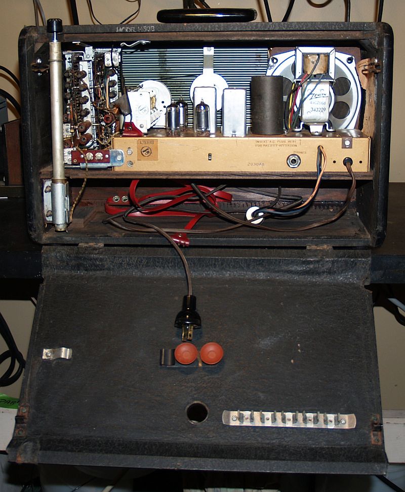
The rado has the original Operating Guide and a sales brocure. They are mounted in a clip on the back cover of the radio. They are access by pulling the back open as shown below.
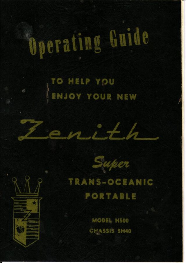
Below are the front and back covers of the Operating Guide.
 |
 |
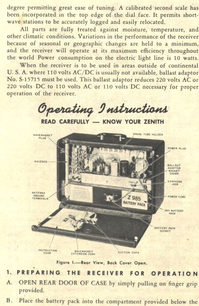
Below is a page from the Operating Guide that shows the inside of the radio with the battery installed.
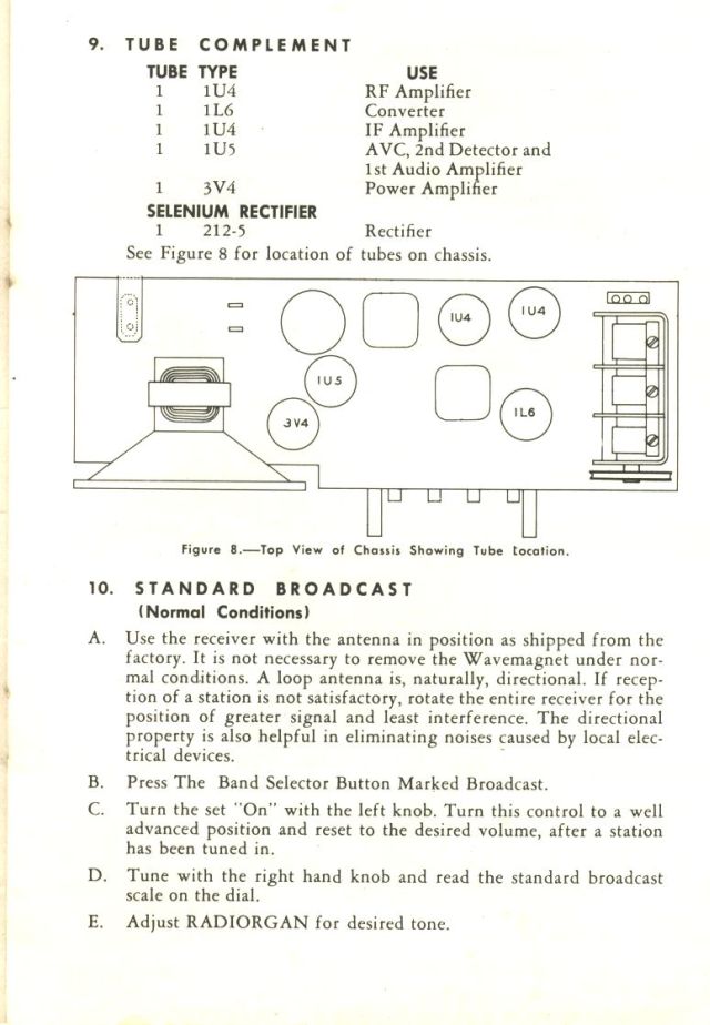
Below is a page from the Operating Guide showing the tube layout.
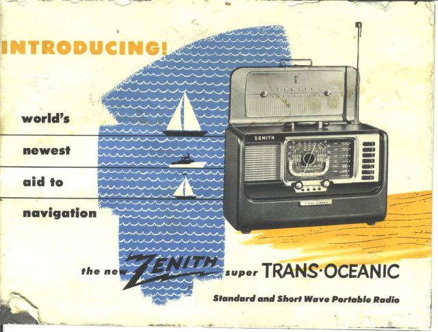
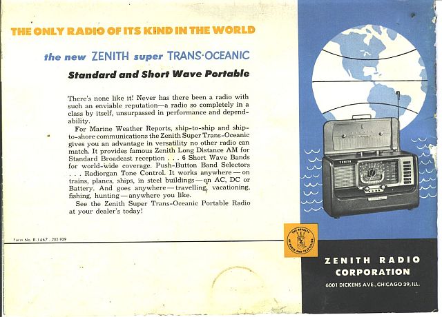
Below are the front and back covers of the sales brochure.
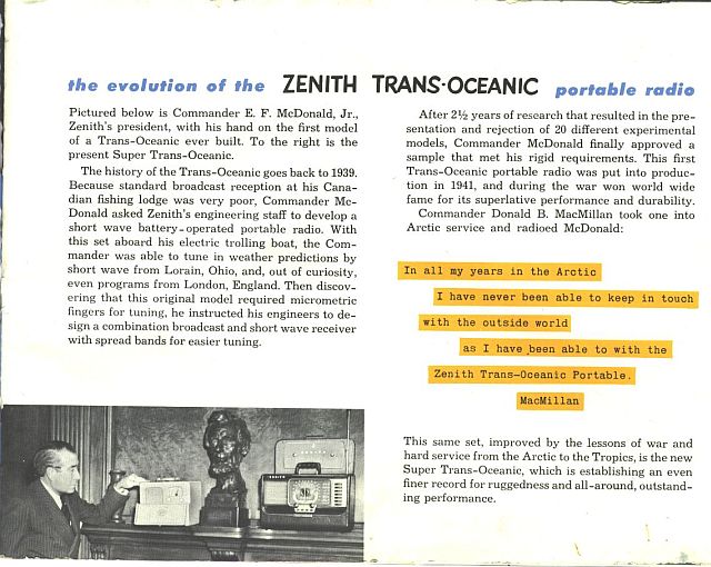
Below is a page from the sales brochure showing the president of Zenith with the first trans-oceanic model and an this model.A bit of history of the trans-oceanic is given.
It should be noted the electrical schematic in the Riders section cited in the above table does not accurately reflect the power supply circuit. In addition, an electrical schematic in a Sams Photofact I found also did not accurately depict the power supply in my receiver. The diferences lie the fact that mine has a voltage switch to select between 117V and 105 V. There is a 2-section resistor in mine where the selector switch shorts out one of the two resistors when operating on 105 V.
The picture below shows the telescoping antenna (Zenith called it the Waverod) exended part way up.
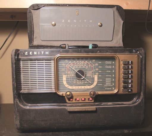
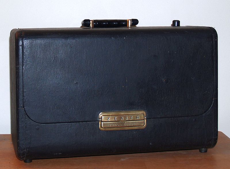
I acquired a second Zenith H500 Transoceanic radio for a really low price. I do not know the year of manufacture. The radio was in fairly good cosmetic shape and I hoped the scarce 1L6 pentagrid converter tube was good. The radio after restoration, cleaning, polishing the plastic, and rubbing black shoe polish on the exterior of the cabinet is shown below.
The radio did not work when I received it. The 1L6 pentagrid converter did not oscillate unless I turned up the line voltage above its rated value. The plate voltages on the 1L6 pentagrid converter and the audio output tube were about 10 volts lower than they should be. I traced the problem to the selenium rectifier that had significant loss. I bypassed the selenium rectifier with a silicon diode and that brought the plate voltages in line with what they should be. The 1L6 pentagrid converter oscillates on all seven frequency bands. The picture below shows the bypassed selenium rectifier.
The picture below shows the complete chassis with the bypassed selenium rectifier. I did not replace the power supply filter capacitor because all voltages are what they should be and the radio has no hum in the audio.
Below is a picture of the rear of the chassis.
Below is a picture of the rear of the radio with the cover opened. This example does not have the owners manual.
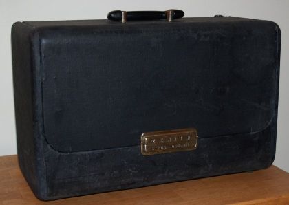
Below is a picture of the radio with the front cover closed.
I have two other Zenith Trans-oceanics that are the transistorized versions.
You can see the Zenith Royal 3000-1 by clicking HERE
You can see the Zenith RD7000Y by clicking HERE